
User Manual
Page 3
...Advanced BIOS Setup Menu 25 2. Exit Menu 33 3 Software Support 24 4.1 Install Operating System 24 4.2 Support CD Information 24 4.2.1 Running Support CD 24 4.2.2 Drivers Menu 24 4.2.3 Utilities Menu 24 4.2.4 ASRock "PC-DIY Live Demo" Program 24 4.2.5 Contact Information 24 ... 23 4. Power Setup Menu 31 4. Boot Setup Menu 32 5. Introduction 4 1.1 Package Contents 4 1.2 Specifications 5 1.3 Motherboard Layout 7 1.4 ASRock I/O Plus 8 TM ...2. Security Setup Menu 30 3. Installation 9 Pre-installation Precautions 9 2.1 CPU Installation 10 2.2 Installation of CPU Fan and ...
...Advanced BIOS Setup Menu 25 2. Exit Menu 33 3 Software Support 24 4.1 Install Operating System 24 4.2 Support CD Information 24 4.2.1 Running Support CD 24 4.2.2 Drivers Menu 24 4.2.3 Utilities Menu 24 4.2.4 ASRock "PC-DIY Live Demo" Program 24 4.2.5 Contact Information 24 ... 23 4. Power Setup Menu 31 4. Boot Setup Menu 32 5. Introduction 4 1.1 Package Contents 4 1.2 Specifications 5 1.3 Motherboard Layout 7 1.4 ASRock I/O Plus 8 TM ...2. Security Setup Menu 30 3. Installation 9 Pre-installation Precautions 9 2.1 CPU Installation 10 2.2 Installation of CPU Fan and ...

User Manual
Page 4
... to change without further notice. Chapter 3 and 4 contain basic BIOS setup and support CD information. ASRock website http://www.asrock.com 1.1 Package Contents 1 x ASRock K7VT6 Motherboard (ATX Form Factor: 12.0-in x 7.0-in, 30.5 cm x 17.8 cm) 1 x ASRock K7VT6 Quick Installation Guide 1 x ASRock K7VT6 Support CD 1 x Ultra ATA 66/100/133 IDE Ribbon Cable (80-conductor) 1 x 3.5-in Appendix on page 25 for purchasing...
... to change without further notice. Chapter 3 and 4 contain basic BIOS setup and support CD information. ASRock website http://www.asrock.com 1.1 Package Contents 1 x ASRock K7VT6 Motherboard (ATX Form Factor: 12.0-in x 7.0-in, 30.5 cm x 17.8 cm) 1 x ASRock K7VT6 Quick Installation Guide 1 x ASRock K7VT6 Support CD 1 x Ultra ATA 66/100/133 IDE Ribbon Cable (80-conductor) 1 x 3.5-in Appendix on page 25 for purchasing...

User Manual
Page 6
...check if the CPU fan on the AGP slot of the system or damage the CPU. BIOS: OS: AMI legal BIOS, Supports "Plug and Play", ACPI 1.1 Compliance Wake-Up Events, SMBIOS 2.3.1 Support, CPU Frequency Stepless Control (only for "CPU Host Frequency" configuration. 6 To improve heat dissipation, remember to Microsoft®... refer to spray thermal grease between the CPU and the heatsink when you set the "CPU Host Frequency" configuration as "Manual" in the Support CD for advanced users' reference, see CAUTION 4) Microsoft® Windows® 98 SE / ME / 2000 / XP Compliant CAUTION! 1.
...check if the CPU fan on the AGP slot of the system or damage the CPU. BIOS: OS: AMI legal BIOS, Supports "Plug and Play", ACPI 1.1 Compliance Wake-Up Events, SMBIOS 2.3.1 Support, CPU Frequency Stepless Control (only for "CPU Host Frequency" configuration. 6 To improve heat dissipation, remember to Microsoft®... refer to spray thermal grease between the CPU and the heatsink when you set the "CPU Host Frequency" configuration as "Manual" in the Support CD for advanced users' reference, see CAUTION 4) Microsoft® Windows® 98 SE / ME / 2000 / XP Compliant CAUTION! 1.

User Manual
Page 15
...see p.7 item 8) Secondary IDE Connector (Black) (39-pin IDE2, see p.7 item 13) SATA1 SATA2 These two Serial ATA (SATA) connectors support SATA data cables for the details. Placing jumper caps over these connectors. Serial ATA (SATA) Data Cable Either end of the connector. 2.6 Connectors...jumper caps over the connectors will cause permanent damage of your hard disk drive to the primary IDE connector (IDE1, blue) and CD-ROM to optimize compatibility and performance, please connect your IDE device vendor for internal storage devices. Serial ATA Connectors (SATA1: see p.7...
...see p.7 item 8) Secondary IDE Connector (Black) (39-pin IDE2, see p.7 item 13) SATA1 SATA2 These two Serial ATA (SATA) connectors support SATA data cables for the details. Placing jumper caps over these connectors. Serial ATA (SATA) Data Cable Either end of the connector. 2.6 Connectors...jumper caps over the connectors will cause permanent damage of your hard disk drive to the primary IDE connector (IDE1, blue) and CD-ROM to optimize compatibility and performance, please connect your IDE device vendor for internal storage devices. Serial ATA Connectors (SATA1: see p.7...
User Manual
Page 16
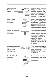
...2.0 ports on the drive. L DUMMY A U D - Front Panel Audio Connector (9-pin AUDIO1) (see p.7 item 21) AUX-R GND GND AUX-L CD-R GND GND CD-L AUX1 CD1 These connectors allow you 6 ready-to function. O U T- R MIC-POWER MIC This is available to receive stereo audio input from sound ...pin USB67) (see p.7 item 28) 1 USB_PWR P-4 P+4 GND USB_PWR P-5 P+5 GND DUMMY This USB45 connector is shared with the USB 2.0 ports 4,5 on ASRock I /O PlusTM provides you to support 2 extra USB 2.0 ports. If the rear USB ports are not sufficient, this connector (JUSB45), the USB ports 4,5 on...
...2.0 ports on the drive. L DUMMY A U D - Front Panel Audio Connector (9-pin AUDIO1) (see p.7 item 21) AUX-R GND GND AUX-L CD-R GND GND CD-L AUX1 CD1 These connectors allow you 6 ready-to function. O U T- R MIC-POWER MIC This is available to receive stereo audio input from sound ...pin USB67) (see p.7 item 28) 1 USB_PWR P-4 P+4 GND USB_PWR P-5 P+5 GND DUMMY This USB45 connector is shared with the USB 2.0 ports 4,5 on ASRock I /O PlusTM provides you to support 2 extra USB 2.0 ports. If the rear USB ports are not sufficient, this connector (JUSB45), the USB ports 4,5 on...

User Manual
Page 19
...! Please refer to the document in the Support CD, "Guide to SATA Hard Disks Installation and RAID Configuration", which is located in the Support CD for boot devices selection appears. WARNING! Start to format and copy files [YN]? STEP 1: Insert the ASRock Support CD into your optical drive to boot your system... following path: .. \ VIA RAID Tool 19 Please insert a floppy diskette into the floppy drive. Please refer to the document in the Support CD, "Guide to VIA RAID Tool", which is located in Windows environment. STEP 4: Then you will need to check the installation guide in ...
...! Please refer to the document in the Support CD, "Guide to SATA Hard Disks Installation and RAID Configuration", which is located in the Support CD for boot devices selection appears. WARNING! Start to format and copy files [YN]? STEP 1: Insert the ASRock Support CD into your optical drive to boot your system... following path: .. \ VIA RAID Tool 19 Please insert a floppy diskette into the floppy drive. Please refer to the document in the Support CD, "Guide to VIA RAID Tool", which is located in Windows environment. STEP 4: Then you will need to check the installation guide in ...

User Manual
Page 24
... the installation wizard to install it. 4.2.4 ASRock PC-DIY Live Demo Program ASRock presents you a multimedia PC-DIY live demo, which shows you need to contact ASRock or want to know more information. 4.2 Support CD Information The Support CD that came with the motherboard contains necessary drivers... and useful utilities that the motherboard supports. Refer to your dealer for further information. 24 or...
... the installation wizard to install it. 4.2.4 ASRock PC-DIY Live Demo Program ASRock presents you a multimedia PC-DIY live demo, which shows you need to contact ASRock or want to know more information. 4.2 Support CD Information The Support CD that came with the motherboard contains necessary drivers... and useful utilities that the motherboard supports. Refer to your dealer for further information. 24 or...


