
User Manual
Page 5
... ATA 133 / Ultra DMA Mode 6 Supports up to 4 IDE Devices Floppy Port: Supports up to 2 Floppy Disk Drives Audio: 5.1 Channels AC'97 Audio LAN: Speed: 802.3u (10/100 Ethernet), Supports Wake-On-LAN Hardware Monitor: CPU Temperature Sensing Motherboard Temperature Sensing CPU Overheat... Shutdown to Protect CPU Life (ASRock U-COP)(see CAUTION 1) CPU Fan Tachometer Chassis Fan Tachometer Voltage Monitoring: +12V, +5V, +3.3V, ...
... ATA 133 / Ultra DMA Mode 6 Supports up to 4 IDE Devices Floppy Port: Supports up to 2 Floppy Disk Drives Audio: 5.1 Channels AC'97 Audio LAN: Speed: 802.3u (10/100 Ethernet), Supports Wake-On-LAN Hardware Monitor: CPU Temperature Sensing Motherboard Temperature Sensing CPU Overheat... Shutdown to Protect CPU Life (ASRock U-COP)(see CAUTION 1) CPU Fan Tachometer Chassis Fan Tachometer Voltage Monitoring: +12V, +5V, +3.3V, ...

User Manual
Page 7
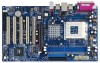
...2.0 T: USB4 1 B: USB5 JUSB45 VIA KT600 CHIPSET Top: Line In Center: Line Out Bottom: Mic In 7 24 2Mb 8 BIOS FSB 400 K7VT6-C 23 22 21 20 19 LAN PHY GAME1 1 SUPER I/O AGP 8X 1.5V_AGP1 PCI1 DDR400 PCI2 1 FSB_SEL0 1 FSB_SEL1 1 FSB_SEL2 1 AUDIO1 JR1 JL1 CMOS ...BATTERY AUDIO CODEC USB2.0 PCI3 1 CLRCMOS2 PCI4 AUX1 CD1 PCI5 FLOPPY1 VIA VT8235CE ATA133 5.1CH 1 SPEAKER1 PWR_LED1 1 PANEL 1 PLED PWRBTN 1 HDLED RST CHA_FAN1...
...2.0 T: USB4 1 B: USB5 JUSB45 VIA KT600 CHIPSET Top: Line In Center: Line Out Bottom: Mic In 7 24 2Mb 8 BIOS FSB 400 K7VT6-C 23 22 21 20 19 LAN PHY GAME1 1 SUPER I/O AGP 8X 1.5V_AGP1 PCI1 DDR400 PCI2 1 FSB_SEL0 1 FSB_SEL1 1 FSB_SEL2 1 AUDIO1 JR1 JL1 CMOS ...BATTERY AUDIO CODEC USB2.0 PCI3 1 CLRCMOS2 PCI4 AUX1 CD1 PCI5 FLOPPY1 VIA VT8235CE ATA133 5.1CH 1 SPEAKER1 PWR_LED1 1 PANEL 1 PLED PWRBTN 1 HDLED RST CHA_FAN1...
User Manual
Page 13
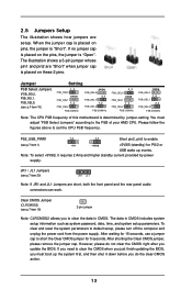
... system parameters to set the CPU FSB frequency. 2.5 Jumpers Setup The illustration shows how jumpers are short, both the front panel and the rear panel audio connectors can work. After shorting the Clear CMOS jumper, please remove the jumper cap. When the jumper cap is placed on these 2 pins. You must...
... system parameters to set the CPU FSB frequency. 2.5 Jumpers Setup The illustration shows how jumpers are short, both the front panel and the rear panel audio connectors can work. After shorting the Clear CMOS jumper, please remove the jumper cap. When the jumper cap is placed on these 2 pins. You must...

User Manual
Page 15
... CD1 15 These connectors allow you use only one IDE device on ASRock I /O PlusTM. When using the front panel USB ports by attaching the front panel USB cable to receive stereo audio input from sound sources such as "Master". Internal Audio Connectors (4-pin CD1, 4-pin AUX1) (CD1: see p.7 item 17) ... refer to function. Besides, to Pin1 Note: Make sure the red-striped side of the cable is shared with the USB 2.0 ports 4,5 on ASRock I /O PlusTM will cause permanent damage of your hard disk drive to the primary IDE connector (IDE1, blue) and CD-ROM to the secondary IDE...
... CD1 15 These connectors allow you use only one IDE device on ASRock I /O PlusTM. When using the front panel USB ports by attaching the front panel USB cable to receive stereo audio input from sound sources such as "Master". Internal Audio Connectors (4-pin CD1, 4-pin AUX1) (CD1: see p.7 item 17) ... refer to function. Besides, to Pin1 Note: Make sure the red-striped side of the cable is shared with the USB 2.0 ports 4,5 on ASRock I /O PlusTM will cause permanent damage of your hard disk drive to the primary IDE connector (IDE1, blue) and CD-ROM to the secondary IDE...

User Manual
Page 16
.... O U T- L GND A U D - Please connect the chassis speaker to this connector and match the black wire to this connector. Front Panel Audio Connector (9-pin AUDIO1) (see p.7 item 23) 1 PLED- O U T- Please connect a chassis fan cable to this connector if the Game port bracket... is an interface for front panel audio cable that allows convenient connection and control of audio devices. CPU Fan Connector (3-pin CPU_FAN1) (see p.7 item 6) Please connect an ATX power supply to this connector...
.... O U T- L GND A U D - Please connect the chassis speaker to this connector and match the black wire to this connector. Front Panel Audio Connector (9-pin AUDIO1) (see p.7 item 23) 1 PLED- O U T- Please connect a chassis fan cable to this connector if the Game port bracket... is an interface for front panel audio cable that allows convenient connection and control of audio devices. CPU Fan Connector (3-pin CPU_FAN1) (see p.7 item 6) Please connect an ATX power supply to this connector...

User Manual
Page 25
... EPP Version Parallel Port IRQ Parallel Port DMA Channel OnBoard Midi Port Midi IRQ Select OnBoard Game Port OnBoard IDE OnBoard LAN OnBoard AC' 97 Audio Auto Auto Auto ECP+EPP 1.9 Auto Auto Disabled 5 200h Enabled Enabled Auto to select Midi IRQ. OnBoard Parallel Port Select Parallel Port address or disable...
... EPP Version Parallel Port IRQ Parallel Port DMA Channel OnBoard Midi Port Midi IRQ Select OnBoard Game Port OnBoard IDE OnBoard LAN OnBoard AC' 97 Audio Auto Auto Auto ECP+EPP 1.9 Auto Auto Disabled 5 200h Enabled Enabled Auto to select Midi IRQ. OnBoard Parallel Port Select Parallel Port address or disable...

User Manual
Page 26
... you to enable or disable the onboard LAN feature. Advanced AMIBIOS SETUP UTILITY - It allows you to monitor the parameters for the onboard AC'97 Audio feature. OnBoard AC'97 Audio Select [Disabled], [Auto] or [Enabled] for CPU temperature, Motherboard temperature, CPU fan speed, and critical voltage.
... you to enable or disable the onboard LAN feature. Advanced AMIBIOS SETUP UTILITY - It allows you to monitor the parameters for the onboard AC'97 Audio feature. OnBoard AC'97 Audio Select [Disabled], [Auto] or [Enabled] for CPU temperature, Motherboard temperature, CPU fan speed, and critical voltage.

Quick Installation Guide
Page 2
... Internal Audio Connector: CD1 (Black) 18 Internal Audio Connector: AUX1 (White) 19 Clear CMOS Jumper (CLRCMOS2) 20 JR1 / JL1 Jumpers 21 Front Panel Audio Connector (AUDIO1) 22 PCI Slots (PCI1- 5) 23 Game Port Connector (GAME1) 24 Flash Memory 25 Shared USB 2.0 Header (JUSB45, Blue) 26 J1 Jumper (FID0, FID1, FID2, FID3, FID4) 2 ASRock K7VT6-C Motherboard
... Internal Audio Connector: CD1 (Black) 18 Internal Audio Connector: AUX1 (White) 19 Clear CMOS Jumper (CLRCMOS2) 20 JR1 / JL1 Jumpers 21 Front Panel Audio Connector (AUDIO1) 22 PCI Slots (PCI1- 5) 23 Game Port Connector (GAME1) 24 Flash Memory 25 Shared USB 2.0 Header (JUSB45, Blue) 26 J1 Jumper (FID0, FID1, FID2, FID3, FID4) 2 ASRock K7VT6-C Motherboard

Quick Installation Guide
Page 5
... AC'97 Audio LAN: Speed: 802.3u (10/100 Ethernet), Supports Wake-On-LAN Hardware Monitor: CPU Temperature Sensing Motherboard Temperature Sensing CPU Overheat Shutdown to Protect CPU Life (ASRock U-COP)(see CAUTION 1) CPU Fan Tachometer Chassis Fan Tachometer Voltage Monitoring: +12V...-to-use USB 2.0 ports on the rear panel, (see CAUTION 3) ASRock I/O PlusTM: 1 PS/2 Mouse Port, 1 PS/2 Keyboard Port, 1 Serial Port: COM1, 1 Parallel Port (ECP/EPP Support) 6 ready-to-use USB 2.0 Ports, 1 RJ-45 Port, Audio Jack: Line In / Line Out / Microphone English 5 ASRock K7VT6-C Motherboard
... AC'97 Audio LAN: Speed: 802.3u (10/100 Ethernet), Supports Wake-On-LAN Hardware Monitor: CPU Temperature Sensing Motherboard Temperature Sensing CPU Overheat Shutdown to Protect CPU Life (ASRock U-COP)(see CAUTION 1) CPU Fan Tachometer Chassis Fan Tachometer Voltage Monitoring: +12V...-to-use USB 2.0 ports on the rear panel, (see CAUTION 3) ASRock I/O PlusTM: 1 PS/2 Mouse Port, 1 PS/2 Keyboard Port, 1 Serial Port: COM1, 1 Parallel Port (ECP/EPP Support) 6 ready-to-use USB 2.0 Ports, 1 RJ-45 Port, Audio Jack: Line In / Line Out / Microphone English 5 ASRock K7VT6-C Motherboard
Quick Installation Guide
Page 10
... for 15 seconds, use a jumper cap to default setup, please turn off the computer and unplug the power cord from the power supply. English 10 ASRock K7VT6-C Motherboard However, the system will work . After waiting for 5 seconds. After shorting the Clear CMOS jumper, please remove the jumper cap. Note: To select +5VSB... Jumper (FID0, FID1, FID2, FID3, FID4) (see p.2 item 20) Note: If JR1 and JL1 Jumpers are short, both the front panel and the rear panel audio connectors can work well without the adjustment of CPU.
... for 15 seconds, use a jumper cap to default setup, please turn off the computer and unplug the power cord from the power supply. English 10 ASRock K7VT6-C Motherboard However, the system will work . After waiting for 5 seconds. After shorting the Clear CMOS jumper, please remove the jumper cap. Note: To select +5VSB... Jumper (FID0, FID1, FID2, FID3, FID4) (see p.2 item 20) Note: If JR1 and JL1 Jumpers are short, both the front panel and the rear panel audio connectors can work well without the adjustment of CPU.

Quick Installation Guide
Page 11
... AUX1 CD1 ROM, DVD-ROM, TV tuner card, or MPEG card. 11 ASRock K7VT6-C Motherboard English Internal Audio Connectors These connectors allow you use only one IDE device on this connector (JUSB45), the USB ports 4,5 on ASRock I /O PlusTM will cause permanent damage of your hard disk drive to the ...primary IDE connector (IDE1, blue) and CD-ROM to (4-pin CD1, 4-pin AUX1) receive stereo audio input from (CD1: see p.2 item 17) sound sources such...
... AUX1 CD1 ROM, DVD-ROM, TV tuner card, or MPEG card. 11 ASRock K7VT6-C Motherboard English Internal Audio Connectors These connectors allow you use only one IDE device on this connector (JUSB45), the USB ports 4,5 on ASRock I /O PlusTM will cause permanent damage of your hard disk drive to the ...primary IDE connector (IDE1, blue) and CD-ROM to (4-pin CD1, 4-pin AUX1) receive stereo audio input from (CD1: see p.2 item 17) sound sources such...

Quick Installation Guide
Page 12
... cable to this connector and match the black wire to this connector. English 12 ASRock K7VT6-C Motherboard Please connect a CPU fan cable to the ground pin. Please connect an ATX power supply to this connector. Front Panel Audio Connector (9-pin AUDIO1) (see p.2 item 21) System Panel Connector (9-pin PANEL1)...item 23) This is installed. Connect a Game cable to this connector if the Game port bracket is an interface for front panel audio cable that allows convenient connection and control of audio devices. This connector accommodates several system front panel functions.
... cable to this connector and match the black wire to this connector. English 12 ASRock K7VT6-C Motherboard Please connect a CPU fan cable to the ground pin. Please connect an ATX power supply to this connector. Front Panel Audio Connector (9-pin AUDIO1) (see p.2 item 21) System Panel Connector (9-pin PANEL1)...item 23) This is installed. Connect a Game cable to this connector if the Game port bracket is an interface for front panel audio cable that allows convenient connection and control of audio devices. This connector accommodates several system front panel functions.


