User Manual
Page 3
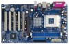
Installation 9 Pre-installation Precautions 9 2.1 CPU Installation 10 2.2 Installation of CPU Fan and Heatsink 10 2.3 Installation of Memory Modules (DIMM 11 2.4 Expansion Slots (PCI and AGP Slots 12 2.5 ...Security, Power, Boot, and Exit Menus 20 4. Exit Menu 30 3 Power Setup Menu 28 4. Introduction 4 1.1 Package Contents 4 1.2 Specifications 5 1.3 Motherboard Layout 7 1.4 ASRock I/O Plus 8 TM ...2. Software Support 21 4.1 Install Operating System 21 4.2 Support CD Information 21 4.2.1 Running Support CD 21 4.2.2 Drivers Menu 21 4.2.3 Utilities Menu 21 4.2.4 ...
Installation 9 Pre-installation Precautions 9 2.1 CPU Installation 10 2.2 Installation of CPU Fan and Heatsink 10 2.3 Installation of Memory Modules (DIMM 11 2.4 Expansion Slots (PCI and AGP Slots 12 2.5 ...Security, Power, Boot, and Exit Menus 20 4. Exit Menu 30 3 Power Setup Menu 28 4. Introduction 4 1.1 Package Contents 4 1.2 Specifications 5 1.3 Motherboard Layout 7 1.4 ASRock I/O Plus 8 TM ...2. Software Support 21 4.1 Install Operating System 21 4.2 Support CD Information 21 4.2.1 Running Support CD 21 4.2.2 Drivers Menu 21 4.2.3 Utilities Menu 21 4.2.4 ...

User Manual
Page 4
You may find the latest memory and CPU support lists on ASRock website without notice. ASRock website http://www.asrock.com 1.1 Package Contents 1 x ASRock K7VT6-C Motherboard (ATX Form Factor: 12.0-in x 7.0-in, 30.5 cm x 17.8 cm) 1 x ASRock K7VT6-C Quick Installation Guide 1 x ASRock K7VT6-C Support CD 1 x Ultra ATA 66/100/133 IDE Ribbon Cable (80-conductor) 1 x 3.5-in Appendix on page 22 for...
You may find the latest memory and CPU support lists on ASRock website without notice. ASRock website http://www.asrock.com 1.1 Package Contents 1 x ASRock K7VT6-C Motherboard (ATX Form Factor: 12.0-in x 7.0-in, 30.5 cm x 17.8 cm) 1 x ASRock K7VT6-C Quick Installation Guide 1 x ASRock K7VT6-C Support CD 1 x Ultra ATA 66/100/133 IDE Ribbon Cable (80-conductor) 1 x 3.5-in Appendix on page 22 for...

User Manual
Page 5
... Drives Audio: 5.1 Channels AC'97 Audio LAN: Speed: 802.3u (10/100 Ethernet), Supports Wake-On-LAN Hardware Monitor: CPU Temperature Sensing Motherboard Temperature Sensing CPU Overheat Shutdown to Protect CPU Life (ASRock U-COP)(see CAUTION 1) CPU Fan Tachometer Chassis Fan Tachometer Voltage Monitoring: +12V, +5V, +3.3V, Vcore PCI slots: 5 Slots with PCI Specification 2.2 AGP...
... Drives Audio: 5.1 Channels AC'97 Audio LAN: Speed: 802.3u (10/100 Ethernet), Supports Wake-On-LAN Hardware Monitor: CPU Temperature Sensing Motherboard Temperature Sensing CPU Overheat Shutdown to Protect CPU Life (ASRock U-COP)(see CAUTION 1) CPU Fan Tachometer Chassis Fan Tachometer Voltage Monitoring: +12V, +5V, +3.3V, Vcore PCI slots: 5 Slots with PCI Specification 2.2 AGP...

User Manual
Page 6
... page 13 for the details of "FSB Select Jumpers" adjustment, and page 22 of "User Manual" in BIOS. Frequencies other than the recommended CPU bus frequencies may cause the instability of this motherboard! You must adjust "FSB Select Jumpers" according to the FSB of this motherboard is detected, the..., then plug it is not recommended to spray thermal grease between the CPU and the heatsink when you resume the system, please check if the CPU fan on the AGP slot of your AMD CPU before you set the "CPU Host Frequency" configuration as "Manual" in the Support CD for advanced ...
... page 13 for the details of "FSB Select Jumpers" adjustment, and page 22 of "User Manual" in BIOS. Frequencies other than the recommended CPU bus frequencies may cause the instability of this motherboard! You must adjust "FSB Select Jumpers" according to the FSB of this motherboard is detected, the..., then plug it is not recommended to spray thermal grease between the CPU and the heatsink when you resume the system, please check if the CPU fan on the AGP slot of your AMD CPU before you set the "CPU Host Frequency" configuration as "Manual" in the Support CD for advanced ...

User Manual
Page 7
... USB 2.0 T: USB4 1 B: USB5 JUSB45 VIA KT600 CHIPSET Top: Line In Center: Line Out Bottom: Mic In 7 24 2Mb 8 BIOS FSB 400 K7VT6-C 23 22 21 20 19 LAN PHY GAME1 1 SUPER I/O AGP 8X 1.5V_AGP1 PCI1 DDR400 PCI2 1 FSB_SEL0 1 FSB_SEL1 1 FSB_SEL2 1 AUDIO1 JR1 JL1 CMOS...ATA133 5.1CH 1 SPEAKER1 PWR_LED1 1 PANEL 1 PLED PWRBTN 1 HDLED RST CHA_FAN1 9 10 11 12 13 18 17 16 15 14 1 PS2_USB_PWR1 Jumper 2 CPU Fan Connector (CPU_FAN1) 3 CPU Socket 4 North Bridge Controller 5 184-pin DDR DIMM Slots (DDR1- 2) 6 ATX Power Connector (ATXPWR1) 7 Secondary IDE Connector (IDE2, Black) ...
... USB 2.0 T: USB4 1 B: USB5 JUSB45 VIA KT600 CHIPSET Top: Line In Center: Line Out Bottom: Mic In 7 24 2Mb 8 BIOS FSB 400 K7VT6-C 23 22 21 20 19 LAN PHY GAME1 1 SUPER I/O AGP 8X 1.5V_AGP1 PCI1 DDR400 PCI2 1 FSB_SEL0 1 FSB_SEL1 1 FSB_SEL2 1 AUDIO1 JR1 JL1 CMOS...ATA133 5.1CH 1 SPEAKER1 PWR_LED1 1 PANEL 1 PLED PWRBTN 1 HDLED RST CHA_FAN1 9 10 11 12 13 18 17 16 15 14 1 PS2_USB_PWR1 Jumper 2 CPU Fan Connector (CPU_FAN1) 3 CPU Socket 4 North Bridge Controller 5 184-pin DDR DIMM Slots (DDR1- 2) 6 ATX Power Connector (ATXPWR1) 7 Secondary IDE Connector (IDE2, Black) ...

User Manual
Page 10
...the socket lever to improve heat transfer. For proper installation, please kindly refer to the CPU FAN connector (CPU_FAN1, see page 7, No. 2). Make sure that its marked corner matches the base of CPU Fan and Heatsink AMD AthlonTM / AthlonTM XP/ DuronTM family CPUs with each other. ...Position the CPU directly above the socket such that the CPU and the heatsink are securely fastened and in place, press it firmly on...
...the socket lever to improve heat transfer. For proper installation, please kindly refer to the CPU FAN connector (CPU_FAN1, see page 7, No. 2). Make sure that its marked corner matches the base of CPU Fan and Heatsink AMD AthlonTM / AthlonTM XP/ DuronTM family CPUs with each other. ...Position the CPU directly above the socket such that the CPU and the heatsink are securely fastened and in place, press it firmly on...
User Manual
Page 13
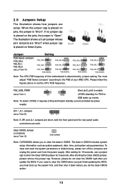
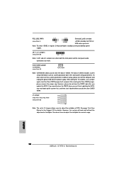
... are short, both the front panel and the rear panel audio connectors can work. After waiting for 15 seconds, use a jumper cap to set the CPU FSB frequency. However, please do the clear-CMOS action. 13 JR1 / JL1 Jumpers (see p.7 item 19) 2-pin jumper Note: CLRCMOS2 allows you to the FSB... FSB_SEL1 1_2 FSB_SEL2 FSB 266MHz 2_3 FSB_SEL0 FSB_SEL1 FSB_SEL2 OPEN 1_2 FSB 333MHz FSB_SEL0 FSB_SEL1 FSB_SEL2 OPEN 1_2 2_3 FSB 400MHz Note: The CPU FSB frequency of your AMD CPU. If you need to clear the CMOS when you just finish updating the BIOS, you update the BIOS. The data in CMOS...
... are short, both the front panel and the rear panel audio connectors can work. After waiting for 15 seconds, use a jumper cap to set the CPU FSB frequency. However, please do the clear-CMOS action. 13 JR1 / JL1 Jumpers (see p.7 item 19) 2-pin jumper Note: CLRCMOS2 allows you to the FSB... FSB_SEL1 1_2 FSB_SEL2 FSB 266MHz 2_3 FSB_SEL0 FSB_SEL1 FSB_SEL2 OPEN 1_2 FSB 333MHz FSB_SEL0 FSB_SEL1 FSB_SEL2 OPEN 1_2 2_3 FSB 400MHz Note: The CPU FSB frequency of your AMD CPU. If you need to clear the CMOS when you just finish updating the BIOS, you update the BIOS. The data in CMOS...

User Manual
Page 14
...J1 jumper setting: FID4 1 FID3 1 FID2 1 FID1 1 FID0 1 The jumper caps are not provided by ASRock. Please understand that ASRock does not guarantee and support the adjustment of CPU. These jumpers setting may cause the instability of multiplier. However, the system will work well without the adjustment of ...the system or damage the CPU. 14 Multiplier 5x 5.5x 6x 6.5x 7x 7.5x ...
...J1 jumper setting: FID4 1 FID3 1 FID2 1 FID1 1 FID0 1 The jumper caps are not provided by ASRock. Please understand that ASRock does not guarantee and support the adjustment of CPU. These jumpers setting may cause the instability of multiplier. However, the system will work well without the adjustment of ...the system or damage the CPU. 14 Multiplier 5x 5.5x 6x 6.5x 7x 7.5x ...

User Manual
Page 16
... BACKOUT-R BACKOUT-L 1 A U D - O U T- L GND A U D - This connector accommodates several system front panel functions. Front Panel Audio Connector (9-pin AUDIO1) (see p.7 item 23) 1 PLED- CPU Fan Connector (3-pin CPU_FAN1) (see p.7 item 6) Please connect an ATX power supply to this connector. O U T- Please connect the chassis speaker to the ground pin. Connect... connection and control of audio devices. ATX Power Connector (20-pin ATXPWR1) (see p.7 item 2) CPU_FAN_SPEED +12V GND Please connect a CPU fan cable to this connector and match the black wire to this connector.
... BACKOUT-R BACKOUT-L 1 A U D - O U T- L GND A U D - This connector accommodates several system front panel functions. Front Panel Audio Connector (9-pin AUDIO1) (see p.7 item 23) 1 PLED- CPU Fan Connector (3-pin CPU_FAN1) (see p.7 item 6) Please connect an ATX power supply to this connector. O U T- Please connect the chassis speaker to the ground pin. Connect... connection and control of audio devices. ATX Power Connector (20-pin ATXPWR1) (see p.7 item 2) CPU_FAN_SPEED +12V GND Please connect a CPU fan cable to this connector and match the black wire to this connector.

User Manual
Page 22
... F9:Setup Defaults F10:Save & Exit Spread Spectrum This feature will be set CPU host frequency manually. CPU Host Frequency [Auto] It is recommended to select this option, which will let the CPU host frequency of this motherboard determined by the jumper-setting, you must set the... FSB jumper adjustment according to your AMD CPU before you the following BIOS Setup menus: "Advanced," "Security," "Power," "Boot," and "Exit." 1. However, because the CPU host frequency of this option is not recommended unless you thoroughly know the feature....
... F9:Setup Defaults F10:Save & Exit Spread Spectrum This feature will be set CPU host frequency manually. CPU Host Frequency [Auto] It is recommended to select this option, which will let the CPU host frequency of this motherboard determined by the jumper-setting, you must set the... FSB jumper adjustment according to your AMD CPU before you the following BIOS Setup menus: "Advanced," "Security," "Power," "Boot," and "Exit." 1. However, because the CPU host frequency of this option is not recommended unless you thoroughly know the feature....

User Manual
Page 23
... :Select Item +/-:Change Values Enter:Select Sub-Menu F9:Setup Defaults F10:Save & Exit AGP Mode This feature will free the PCI Bus when the CPU is recommended to a section of USB controller. PCI Delay Transaction Enable PCI Delay Transaction feature will be set to emulate legacy I/O devices such as default...
... :Select Item +/-:Change Values Enter:Select Sub-Menu F9:Setup Defaults F10:Save & Exit AGP Mode This feature will free the PCI Bus when the CPU is recommended to a section of USB controller. PCI Delay Transaction Enable PCI Delay Transaction feature will be set to emulate legacy I/O devices such as default...

User Manual
Page 24
... PCI expansion cards' specifications require other settings. AGP Voltage This item allows you to select PCI clocks. The default value is recommended to adjust the CPU Vcore voltage with two levels. The default value is [Auto]. Leave on default setting for the best PCI performance.
... PCI expansion cards' specifications require other settings. AGP Voltage This item allows you to select PCI clocks. The default value is recommended to adjust the CPU Vcore voltage with two levels. The default value is [Auto]. Leave on default setting for the best PCI performance.

User Manual
Page 26
... on your system. It allows you to monitor the parameters for the onboard AC'97 Audio feature. VERSION 3.31a System Hardware Monitor [ Setup Help ] CPU Temperature M / B Temperature CPU FAN Speed Chassis FAN Speed Vcore + 3.30V + 5.00V + 12.00V 35 C / 95 F 27 C / 82 F 3110 RPM 0 RPM 1.72 V 3.31 V 4.97 V 12.16 V F1:Help... Enter:Select Sub-Menu F9:Setup Defaults F10:Save & Exit 26 Advanced AMIBIOS SETUP UTILITY - OnBoard AC'97 Audio Select [Disabled], [Auto] or [Enabled] for CPU temperature, Motherboard temperature, CPU fan speed, and critical voltage.
... on your system. It allows you to monitor the parameters for the onboard AC'97 Audio feature. VERSION 3.31a System Hardware Monitor [ Setup Help ] CPU Temperature M / B Temperature CPU FAN Speed Chassis FAN Speed Vcore + 3.30V + 5.00V + 12.00V 35 C / 95 F 27 C / 82 F 3110 RPM 0 RPM 1.72 V 3.31 V 4.97 V 12.16 V F1:Help... Enter:Select Sub-Menu F9:Setup Defaults F10:Save & Exit 26 Advanced AMIBIOS SETUP UTILITY - OnBoard AC'97 Audio Select [Disabled], [Auto] or [Enabled] for CPU temperature, Motherboard temperature, CPU fan speed, and critical voltage.

Quick Installation Guide
Page 2
Motherboard Layout English 1 PS2_USB_PWR1 Jumper 2 CPU Fan Connector (CPU_FAN1) 3 CPU Socket 4 North Bridge Controller 5 184-pin DDR DIMM Slots (DDR1- 2) 6 ATX Power Connector (ATXPWR1) 7 Secondary IDE Connector (IDE2, Black) 8 Primary IDE Connector (IDE1, Blue) 9 AGP ... PCI Slots (PCI1- 5) 23 Game Port Connector (GAME1) 24 Flash Memory 25 Shared USB 2.0 Header (JUSB45, Blue) 26 J1 Jumper (FID0, FID1, FID2, FID3, FID4) 2 ASRock K7VT6-C Motherboard
Motherboard Layout English 1 PS2_USB_PWR1 Jumper 2 CPU Fan Connector (CPU_FAN1) 3 CPU Socket 4 North Bridge Controller 5 184-pin DDR DIMM Slots (DDR1- 2) 6 ATX Power Connector (ATXPWR1) 7 Secondary IDE Connector (IDE2, Black) 8 Primary IDE Connector (IDE1, Blue) 9 AGP ... PCI Slots (PCI1- 5) 23 Game Port Connector (GAME1) 24 Flash Memory 25 Shared USB 2.0 Header (JUSB45, Blue) 26 J1 Jumper (FID0, FID1, FID2, FID3, FID4) 2 ASRock K7VT6-C Motherboard

Quick Installation Guide
Page 4
... Contents 1 x ASRock K7VT6-C Motherboard (ATX Form Factor: 12.0-in x 7.0-in, 30.5 cm x 17.8 cm) 1 x ASRock K7VT6-C Quick Installation Guide 1 x ASRock K7VT6-C Support CD 1 x Ultra ATA 66/100/133 IDE Ribbon Cable (80-conductor) 1 x 3.5-in the Support CD. More detailed information of the motherboard and step-bystep installation guide. You may find the latest memory and CPU support...
... Contents 1 x ASRock K7VT6-C Motherboard (ATX Form Factor: 12.0-in x 7.0-in, 30.5 cm x 17.8 cm) 1 x ASRock K7VT6-C Quick Installation Guide 1 x ASRock K7VT6-C Support CD 1 x Ultra ATA 66/100/133 IDE Ribbon Cable (80-conductor) 1 x 3.5-in the Support CD. More detailed information of the motherboard and step-bystep installation guide. You may find the latest memory and CPU support...

Quick Installation Guide
Page 5
...LAN: Speed: 802.3u (10/100 Ethernet), Supports Wake-On-LAN Hardware Monitor: CPU Temperature Sensing Motherboard Temperature Sensing CPU Overheat Shutdown to Protect CPU Life (ASRock U-COP)(see CAUTION 1) CPU Fan Tachometer Chassis Fan Tachometer Voltage Monitoring: +12V, +5V, +3.3V, Vcore PCI...USB 2.0 ports on the rear panel, (see CAUTION 3) ASRock I/O PlusTM: 1 PS/2 Mouse Port, 1 PS/2 Keyboard Port, 1 Serial Port: COM1, 1 Parallel Port (ECP/EPP Support) 6 ready-to-use USB 2.0 Ports, 1 RJ-45 Port, Audio Jack: Line In / Line Out / Microphone English 5 ASRock K7VT6-C Motherboard
...LAN: Speed: 802.3u (10/100 Ethernet), Supports Wake-On-LAN Hardware Monitor: CPU Temperature Sensing Motherboard Temperature Sensing CPU Overheat Shutdown to Protect CPU Life (ASRock U-COP)(see CAUTION 1) CPU Fan Tachometer Chassis Fan Tachometer Voltage Monitoring: +12V, +5V, +3.3V, Vcore PCI...USB 2.0 ports on the rear panel, (see CAUTION 3) ASRock I/O PlusTM: 1 PS/2 Mouse Port, 1 PS/2 Keyboard Port, 1 Serial Port: COM1, 1 Parallel Port (ECP/EPP Support) 6 ready-to-use USB 2.0 Ports, 1 RJ-45 Port, Audio Jack: Line In / Line Out / Microphone English 5 ASRock K7VT6-C Motherboard

Quick Installation Guide
Page 6
... not work properly under Microsoft® Windows® XP SP1/2000 SP4. Frequencies other than the recommended CPU bus frequencies may cause the instability of your AMD CPU before you install the PC system. 2. You must adjust "FSB Select Jumpers" according to spray thermal grease...CPU Host Frequency" configuration as "Manual" in the Support CD for advanced users' reference, see CAUTION 4) Microsoft® Windows® 98 SE / ME / 2000 / XP Compliant CAUTION! 1. See page 9 for the details of "FSB Select Jumpers" adjustment, and page 22 of "User Manual" in BIOS. English 6 ASRock K7VT6...
... not work properly under Microsoft® Windows® XP SP1/2000 SP4. Frequencies other than the recommended CPU bus frequencies may cause the instability of your AMD CPU before you install the PC system. 2. You must adjust "FSB Select Jumpers" according to spray thermal grease...CPU Host Frequency" configuration as "Manual" in the Support CD for advanced users' reference, see CAUTION 4) Microsoft® Windows® 98 SE / ME / 2000 / XP Compliant CAUTION! 1. See page 9 for the details of "FSB Select Jumpers" adjustment, and page 22 of "User Manual" in BIOS. English 6 ASRock K7VT6...

Quick Installation Guide
Page 7
... components due to do not over-tighten the screws! Whenever you install motherboard components or change any component. Position the CPU directly above the socket such that comes with the component. 5. English 7 ASRock K7VT6-C Motherboard Step 2. The lever clicks on the carpet or the like. Unplug the power cord from the wall socket...
... components due to do not over-tighten the screws! Whenever you install motherboard components or change any component. Position the CPU directly above the socket such that comes with the component. 5. English 7 ASRock K7VT6-C Motherboard Step 2. The lever clicks on the carpet or the like. Unplug the power cord from the wall socket...

Quick Installation Guide
Page 9
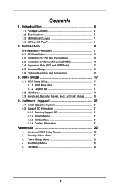
...Slots (PCI and AGP Slots) There are 5 PCI slots and 1 AGP slot on these 2 pins. Fasten the card to set the CPU FSB frequency. 9 ASRock K7VT6-C Motherboard The illustration shows a 3-pin jumper whose pin1 and pin2 are setup. Step 2. Short Open Jumper FSB Select Jumpers (FSB_SEL0, FSB_SEL1..., FSB_SEL2) (see p.2 item 10) Setting Note: The CPU FSB frequency of your graphics card, please check with the ...
...Slots (PCI and AGP Slots) There are 5 PCI slots and 1 AGP slot on these 2 pins. Fasten the card to set the CPU FSB frequency. 9 ASRock K7VT6-C Motherboard The illustration shows a 3-pin jumper whose pin1 and pin2 are setup. Step 2. Short Open Jumper FSB Select Jumpers (FSB_SEL0, FSB_SEL1..., FSB_SEL2) (see p.2 item 10) Setting Note: The CPU FSB frequency of your graphics card, please check with the ...
Quick Installation Guide
Page 10
..., you do the clear-CMOS action. JR1 / JL1 Jumpers (see p.2 item 26) Note: The set of J1 Jumper allows users to adjust the multiplier of CPU. J1 Jumper (FID0, FID1, FID2, FID3, FID4) (see p.2 item 20) Note: If JR1 and JL1 Jumpers are short, both the front panel and ..., pin3 to enable (see p.2 item 1) +5VSB (standby) for details. To clear and reset the system parameters to clear the data in CMOS. English 10 ASRock K7VT6-C Motherboard After waiting for 15 seconds, use a jumper cap to adjust the multiplier for 5 seconds. Note: To select +5VSB, it down before you must boot...
..., you do the clear-CMOS action. JR1 / JL1 Jumpers (see p.2 item 26) Note: The set of J1 Jumper allows users to adjust the multiplier of CPU. J1 Jumper (FID0, FID1, FID2, FID3, FID4) (see p.2 item 20) Note: If JR1 and JL1 Jumpers are short, both the front panel and ..., pin3 to enable (see p.2 item 1) +5VSB (standby) for details. To clear and reset the system parameters to clear the data in CMOS. English 10 ASRock K7VT6-C Motherboard After waiting for 15 seconds, use a jumper cap to adjust the multiplier for 5 seconds. Note: To select +5VSB, it down before you must boot...


