User Manual
Page 3
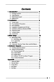
Power Menu 22 4. Security Menu 21 3. Advanced Menu 19 2. Boot Menu 23 5. Contents 1 Introduction 4 1.1 Package Contents 4 1.2 Specifications 4 1.3 Motherboard Layout 6 1.4 ASRock I/O 7 TM ...2 Installation 8 2.1 Screw Holes 8 2.2 Pre-installation Precautions 8 2.3 CPU Installation 8 2.4 Installation of Heatsink and CPU fan 9 2.5 Installation of... System 18 4.2 Support CD Information 18 4.2.1 Running Support CD 18 4.2.2 Drivers Menu 18 4.2.3 Utilities Menu 18 4.2.4 ASRock "PC-DIY Live Demo" Program 18 4.2.5 Contact Information 18 Appendix 19 1. Exit Menu 23 3
Power Menu 22 4. Security Menu 21 3. Advanced Menu 19 2. Boot Menu 23 5. Contents 1 Introduction 4 1.1 Package Contents 4 1.2 Specifications 4 1.3 Motherboard Layout 6 1.4 ASRock I/O 7 TM ...2 Installation 8 2.1 Screw Holes 8 2.2 Pre-installation Precautions 8 2.3 CPU Installation 8 2.4 Installation of Heatsink and CPU fan 9 2.5 Installation of... System 18 4.2 Support CD Information 18 4.2.1 Running Support CD 18 4.2.2 Drivers Menu 18 4.2.3 Utilities Menu 18 4.2.4 ASRock "PC-DIY Live Demo" Program 18 4.2.5 Contact Information 18 Appendix 19 1. Exit Menu 23 3
User Manual
Page 4
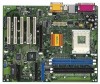
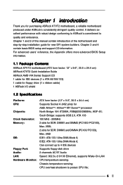
...temperature sensing; For advanced users' reference, the Appendix offers more advanced BIOS Setup information. 1.1 Package Contents ASRock K7VT2 motherboard (ATX form factor: 12" x 9.6", 30.5 x 24.4 cm) ASRock K7VT2 Quick Installation Guide ASRock AMD-VIA Series Support CD 1 cable for IDE devices (1 x ATA 66/100/133) 1 cable ...IDE2: ATA 133 / Ultra DMA Mode 6; Chapter 1 and 2 of this manual contain introduction of the motherboard and step-by-step installation guide for purchasing ASRock K7VT2 motherboard, a reliable motherboard produced under ASRock's consistently stringent quality control.
...temperature sensing; For advanced users' reference, the Appendix offers more advanced BIOS Setup information. 1.1 Package Contents ASRock K7VT2 motherboard (ATX form factor: 12" x 9.6", 30.5 x 24.4 cm) ASRock K7VT2 Quick Installation Guide ASRock AMD-VIA Series Support CD 1 cable for IDE devices (1 x ATA 66/100/133) 1 cable ...IDE2: ATA 133 / Ultra DMA Mode 6; Chapter 1 and 2 of this manual contain introduction of the motherboard and step-by-step installation guide for purchasing ASRock K7VT2 motherboard, a reliable motherboard produced under ASRock's consistently stringent quality control.
User Manual
Page 5
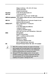
... Line In/ Microphone + Game port BIOS: AMI legal BIOS; ACPI 1.1 compliance wake up events; Although K7VT2 offers stepless control, it is detected, the system will be disabled. Chassis fan tachometer PCI slots: 5..., supports 3.3v / 1.5v, 4X / 2X / 1X AGP cards AMR slot (optional): 1 slot, supports ASRock MR card, shares the bracket with the slot PCI 5 USB 2.0: 4 default USB ports and 1 extra set ... fan on the chassis will automatically shutdown and the power button on the motherboard functions properly before you resume the system. 2. Voltage monitoring: +12V, +5V, +3V...
... Line In/ Microphone + Game port BIOS: AMI legal BIOS; ACPI 1.1 compliance wake up events; Although K7VT2 offers stepless control, it is detected, the system will be disabled. Chassis fan tachometer PCI slots: 5..., supports 3.3v / 1.5v, 4X / 2X / 1X AGP cards AMR slot (optional): 1 slot, supports ASRock MR card, shares the bracket with the slot PCI 5 USB 2.0: 4 default USB ports and 1 extra set ... fan on the chassis will automatically shutdown and the power button on the motherboard functions properly before you resume the system. 2. Voltage monitoring: +12V, +5V, +3V...
User Manual
Page 8
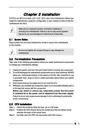
...Position the CPU directly above the socket such that its marked corner matches the base of your motherboard directly on a grounded antistatic pad or in place. 8 Step 3. Chapter 2 Installation K7VT2 is detached from the wall socket before you install or remove any component, place it on ...the carpet or the like. Before you handle components. 3. Carefully insert the CPU into the socket until it . To avoid damaging the motherboard components due to a ...
...Position the CPU directly above the socket such that its marked corner matches the base of your motherboard directly on a grounded antistatic pad or in place. 8 Step 3. Chapter 2 Installation K7VT2 is detached from the wall socket before you install or remove any component, place it on ...the carpet or the like. Before you handle components. 3. Carefully insert the CPU into the socket until it . To avoid damaging the motherboard components due to a ...
User Manual
Page 10
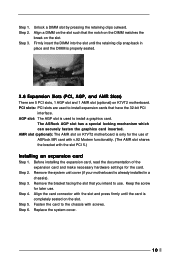
...for the card. Step 2. Remove the bracket facing the slot that the notch on the DIMM matches the break on K7VT2 motherboard is used to install a graphics card. Step 6. Align a DIMM on K7VT2 motherboard. Fasten the card to use . PCI slots: PCI slots are 5 PCI slots, 1 AGP slot and 1 ...of the expansion card and make necessary hardware settings for later use . Step 2. Before installing the expansion card, read the documentation of ASRock MR card with v.92 Modem functionality. (The AMR slot shares the bracket with screws. Align the card connector with the slot and ...
...for the card. Step 2. Remove the bracket facing the slot that the notch on the DIMM matches the break on K7VT2 motherboard is used to install a graphics card. Step 6. Align a DIMM on K7VT2 motherboard. Fasten the card to use . PCI slots: PCI slots are 5 PCI slots, 1 AGP slot and 1 ...of the expansion card and make necessary hardware settings for later use . Step 2. Before installing the expansion card, read the documentation of ASRock MR card with v.92 Modem functionality. (The AMR slot shares the bracket with screws. Align the card connector with the slot and ...
User Manual
Page 12
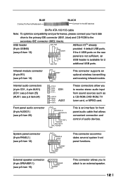
... PANEL1) (see p.6 item 20) GND +5VA BACKOUT-R BACKOUT-L 1 A U D - External speaker connector (4-pin SPEAKER 1) (see p.6 item 13) USB_PWR P-5 P+5 GND DUMMY ASRock I/OTM already provided 4 default USB ports. L DUMMY A U D - BLUE Connect to the motherboard BLACK Connect to the IDE devices 80-Pin ATA 100/133 cable Note: To optimize compatibility and performance, please connect...
... PANEL1) (see p.6 item 20) GND +5VA BACKOUT-R BACKOUT-L 1 A U D - External speaker connector (4-pin SPEAKER 1) (see p.6 item 13) USB_PWR P-5 P+5 GND DUMMY ASRock I/OTM already provided 4 default USB ports. L DUMMY A U D - BLUE Connect to the motherboard BLACK Connect to the IDE devices 80-Pin ATA 100/133 cable Note: To optimize compatibility and performance, please connect...
User Manual
Page 14
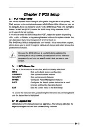
... System EXIT Exits the current menu or the BIOS Setup To access the menu bar items, press the right or left arrow key on the motherboard stores the BIOS Setup Utility. It is a menu-driven program, which allows you to scroll through its test routines. The following table lists the keys...
... System EXIT Exits the current menu or the BIOS Setup To access the menu bar items, press the right or left arrow key on the motherboard stores the BIOS Setup Utility. It is a menu-driven program, which allows you to scroll through its test routines. The following table lists the keys...
User Manual
Page 18
...demo program, you need to contact ASRock or want to know more information. 4.2 Support CD Information The Support CD that came with the motherboard contains necessary drivers and useful utilities that the motherboard supports. Because motherboard settings and hardware options vary, use...The Drivers Menu shows the available devices drivers if the system detects installed devices. Refer to ASRock's website: http://www.asrock.com; Chapter 4 Software Support 4.1 Install Operating System This motherboard supports various Windows operating systems (98SE / ME / 2000 / XP). You can run ...
...demo program, you need to contact ASRock or want to know more information. 4.2 Support CD Information The Support CD that came with the motherboard contains necessary drivers and useful utilities that the motherboard supports. Because motherboard settings and hardware options vary, use...The Drivers Menu shows the available devices drivers if the system detects installed devices. Refer to ASRock's website: http://www.asrock.com; Chapter 4 Software Support 4.1 Install Operating System This motherboard supports various Windows operating systems (98SE / ME / 2000 / XP). You can run ...
User Manual
Page 19
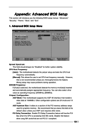
..."Power," "Boot," and "Exit." 1. Appendix: Advanced BIOS Setup This section will free the PCI Bus when the CPU is selected, the motherboard detects the memory module(s) inserted and automatically assigns appropriate frequency. AGP Aperture Size: It refers to set CPU host frequency manually. PCI Delay Transaction...[200MHz], [266MHz]. Wrong setup may cause problems during operation. You can also select other sizes. CPU Host Frequency: [Auto]: The motherboard detects the jumper setup and sets the CPU host frequency automatically. [Manual]: This allows the user to a section of the PCI memory...
..."Power," "Boot," and "Exit." 1. Appendix: Advanced BIOS Setup This section will free the PCI Bus when the CPU is selected, the motherboard detects the memory module(s) inserted and automatically assigns appropriate frequency. AGP Aperture Size: It refers to set CPU host frequency manually. PCI Delay Transaction...[200MHz], [266MHz]. Wrong setup may cause problems during operation. You can also select other sizes. CPU Host Frequency: [Auto]: The motherboard detects the jumper setup and sets the CPU host frequency automatically. [Manual]: This allows the user to a section of the PCI memory...
User Manual
Page 21
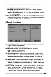
... 6 alphanumeric characters combination. If you already have a password, you to monitor the parameters for "Password Check". Password Check: Select the check points for CPU temperature, Motherboard temperature, CPU fan speed, and critical voltage. 2. Configuration options: , . If option is selected, the "Password Check" is performed before both boot-up and BIOS setup...
... 6 alphanumeric characters combination. If you already have a password, you to monitor the parameters for "Password Check". Password Check: Select the check points for CPU temperature, Motherboard temperature, CPU fan speed, and critical voltage. 2. Configuration options: , . If option is selected, the "Password Check" is performed before both boot-up and BIOS setup...

