User Manual
Page 3
Contents 1 Introduction 4 1.1 Package Contents 4 1.2 Specifications 5 1.3 Motherboard Layout 7 1.4 ASRock I/OTM 8 2 Installation 9 2.1 Screw Holes 9 2.2 Pre-installation Precautions 9 2.3 CPU Installation 10 2.4 Installation of Heatsink and CPU fan 10 2.5 ...4 Software Support 22 4.1 Installing Operating System 22 4.2 Support CD Information 22 4.2.1 Running Support CD 22 4.2.2 Drivers Menu 22 4.2.3 Utilities Menu 22 4.2.4 ASRock "PC-DIY Live Demo" Program 22 4.2.5 Contact Information 22 Appendix 23 1. Power Menu 28 4. Security Menu 27 3. Exit Menu 30 3 Advanced Menu...
Contents 1 Introduction 4 1.1 Package Contents 4 1.2 Specifications 5 1.3 Motherboard Layout 7 1.4 ASRock I/OTM 8 2 Installation 9 2.1 Screw Holes 9 2.2 Pre-installation Precautions 9 2.3 CPU Installation 10 2.4 Installation of Heatsink and CPU fan 10 2.5 ...4 Software Support 22 4.1 Installing Operating System 22 4.2 Support CD Information 22 4.2.1 Running Support CD 22 4.2.2 Drivers Menu 22 4.2.3 Utilities Menu 22 4.2.4 ASRock "PC-DIY Live Demo" Program 22 4.2.5 Contact Information 22 Appendix 23 1. Power Menu 28 4. Security Menu 27 3. Exit Menu 30 3 Advanced Menu...
User Manual
Page 4
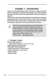
... as well. In case any modifications of this manual will be subject to quality and endurance. ASRock website http://www.asrock.com 1.1 Package Contents ASRock K7VM3 motherboard (Micro ATX form factor: 9.6" x 7.5", 24.4 x 19.1 cm) ASRock K7VM3 Quick Installation Guide ASRock AMD-VIA Series Support CD 1 cable for IDE devices (1 x ATA 66/100/133) 1 cable for new DIY system...
... as well. In case any modifications of this manual will be subject to quality and endurance. ASRock website http://www.asrock.com 1.1 Package Contents ASRock K7VM3 motherboard (Micro ATX form factor: 9.6" x 7.5", 24.4 x 19.1 cm) ASRock K7VM3 Quick Installation Guide ASRock AMD-VIA Series Support CD 1 cable for IDE devices (1 x ATA 66/100/133) 1 cable for new DIY system...
User Manual
Page 6
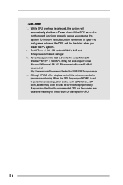
...the CPU. 6 Please refer to perform over clocking. Do NOT use a 3.3V AGP card on the motherboard functions properly before you install the PC system. 2. CAUTION! 1. Although K7VM3 offers stepless control, it is detected, the system will also be overclocked proportionally. It may not work ...properly under Microsoft® Windows® XP SP1 / 2000 SP4. Please check if the CPU fan on K7VM3's AGP slot! To improve heat dissipation, remember to perform over clocking, other than the recommended CPU bus frequencies may cause permanent damage! ...
...the CPU. 6 Please refer to perform over clocking. Do NOT use a 3.3V AGP card on the motherboard functions properly before you install the PC system. 2. CAUTION! 1. Although K7VM3 offers stepless control, it is detected, the system will also be overclocked proportionally. It may not work ...properly under Microsoft® Windows® XP SP1 / 2000 SP4. Please check if the CPU fan on K7VM3's AGP slot! To improve heat dissipation, remember to perform over clocking, other than the recommended CPU bus frequencies may cause permanent damage! ...
User Manual
Page 7
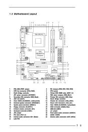
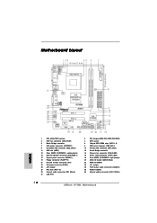
1.3 Motherboard Layout 1 23 45 6 7 19.1cm (7.5 in) PS/2 Mouse PS/2 Keyboard PS2_USB_PWR1 1 1 FID0 1 FID1 1 FID2 1 FID3 1 FID4 CPU_FAN1 VGA DDR1 (64/72 bit, 184-pin module) ... 2.0 Ports USB 2.0 Ports Line out LiLInnineein MMIniicc in AUDIO CODEC AUDIO1 1 JR1 JL1 COM1 1 2MB BIOS LAN PHY VIA KM266Pro Chipset 8 1 FSB_SEL1 IDE1 IDE2 ` ATA133 K7VM3 AGP1 PCI 1 01 23 Super I/O PCI 2 USB 2.0 IR1 AMR1 1 USB45 1 VIA VT8235 CMOS Battery CLRCMOS2 CLRCMOS1 FLOPPY1 CHA_FAN1 SPEAKER1 1 PWR_LED11 PLED PWRBTN PANEL 1 1 HDLED RST...
1.3 Motherboard Layout 1 23 45 6 7 19.1cm (7.5 in) PS/2 Mouse PS/2 Keyboard PS2_USB_PWR1 1 1 FID0 1 FID1 1 FID2 1 FID3 1 FID4 CPU_FAN1 VGA DDR1 (64/72 bit, 184-pin module) ... 2.0 Ports USB 2.0 Ports Line out LiLInnineein MMIniicc in AUDIO CODEC AUDIO1 1 JR1 JL1 COM1 1 2MB BIOS LAN PHY VIA KM266Pro Chipset 8 1 FSB_SEL1 IDE1 IDE2 ` ATA133 K7VM3 AGP1 PCI 1 01 23 Super I/O PCI 2 USB 2.0 IR1 AMR1 1 USB45 1 VIA VT8235 CMOS Battery CLRCMOS2 CLRCMOS1 FLOPPY1 CHA_FAN1 SPEAKER1 1 PWR_LED11 PLED PWRBTN PANEL 1 1 HDLED RST...

User Manual
Page 9
...K7VM3 is detached from the wall socket before touching any component. 2. Failure to do so may cause physical injuries to you and damages to motherboard components. 2.1 Screw Holes Place screws into it on the carpet or the like. Unplug the power cord from the power supply. Before you install motherboard...use a grounded wrist strap or touch a safety grounded object before installing or removing the motherboard. Failure to do not touch the ICs. 4. Also remember to the motherboard, peripherals, and/or components. 9 Whenever you handle components. 3. Make sure to static ...
...K7VM3 is detached from the wall socket before touching any component. 2. Failure to do so may cause physical injuries to you and damages to motherboard components. 2.1 Screw Holes Place screws into it on the carpet or the like. Unplug the power cord from the power supply. Before you install motherboard...use a grounded wrist strap or touch a safety grounded object before installing or removing the motherboard. Failure to do not touch the ICs. 4. Also remember to the motherboard, peripherals, and/or components. 9 Whenever you handle components. 3. Make sure to static ...
User Manual
Page 10
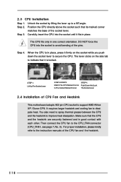
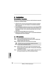
... 2.4 Installation of the CPU fan and the heatsink. 10 For proper installation, please kindly refer to the instruction manuals of CPU Fan and Heatsink This motherboard adopts 462-pin CPU socket to indicate that its marked corner matches the base of the pins. Step 2. You also need to spray thermal grease...
... 2.4 Installation of the CPU fan and the heatsink. 10 For proper installation, please kindly refer to the instruction manuals of CPU Fan and Heatsink This motherboard adopts 462-pin CPU socket to indicate that its marked corner matches the base of the pins. Step 2. You also need to spray thermal grease...
User Manual
Page 11
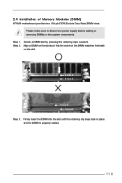
Please make sure to disconnect power supply before adding or removing DIMMs or the system components. Step 2. Step 1. Unlock a DIMM slot by pressing the retaining clips outward. Firmly insert the DIMM into the slot until the retaining clip snap back in place and the DIMM is properly seated. 11 notch break notch break Step 3. Align a DIMM on the slot such that the notch on the DIMM matches the break on the slot. 2.5 Installation of Memory Modules (DIMM) K7VM3 motherboard provides two 184-pin DDR (Double Data Rate) DIMM slots.
Please make sure to disconnect power supply before adding or removing DIMMs or the system components. Step 2. Step 1. Unlock a DIMM slot by pressing the retaining clips outward. Firmly insert the DIMM into the slot until the retaining clip snap back in place and the DIMM is properly seated. 11 notch break notch break Step 3. Align a DIMM on the slot such that the notch on the DIMM matches the break on the slot. 2.5 Installation of Memory Modules (DIMM) K7VM3 motherboard provides two 184-pin DDR (Double Data Rate) DIMM slots.

User Manual
Page 12
...ASRock AGP slot has a special locking mechanism which can securely fasten the graphics card inserted. Installing an expansion card Step 1. Step 4. Step 5. Before installing the expansion card, read the documentation of the expansion card and make necessary hardware settings for later use . Remove the system unit cover (if your motherboard... is completely seated on K7VM3 motherboard. Align the card connector with the slot and press firmly until the card is already installed in...
...ASRock AGP slot has a special locking mechanism which can securely fasten the graphics card inserted. Installing an expansion card Step 1. Step 4. Step 5. Before installing the expansion card, read the documentation of the expansion card and make necessary hardware settings for later use . Remove the system unit cover (if your motherboard... is completely seated on K7VM3 motherboard. Align the card connector with the slot and press firmly until the card is already installed in...

User Manual
Page 13
Note: To select +5VSB, it requires 2 Amp and higher standby current provided by means of the adjustment of this motherboard is by power supply. 2.7 Jumpers Setup The illustration shows how jumpers are "SHORT". PS2_USB_PWR1 1_2 2_3 Short pin2, pin3 to set the CPU front side ...
Note: To select +5VSB, it requires 2 Amp and higher standby current provided by means of the adjustment of this motherboard is by power supply. 2.7 Jumpers Setup The illustration shows how jumpers are "SHORT". PS2_USB_PWR1 1_2 2_3 Short pin2, pin3 to set the CPU front side ...
User Manual
Page 16
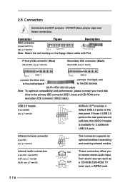
... (4-pin CD1, 4-pin AUX1) (CD1: see p.7 item 29) (AUX1: see p.7 item 9) PIN1 IDE1 PIN1 IDE2 connect the blue end connect the black end to the motherboard to the IDE devices 80-Pin ATA 100/133 cable Note: To optimize compatibility and performance, please connect your hard disk drive to the primary..., this USB 2.0 header is available for 2 additional USB 2.0 ports. Connector Figure Description FDD connector (33-pin FLOPPY1) (see p.7 item 20) USB_PWR P-5 P+5 GND DUMMY 1 GND P+4 P-4 USB_PWR ASRock I/OTM provides 4 default USB 2.0 ports on the floppy ribbon cable with Pin1.
... (4-pin CD1, 4-pin AUX1) (CD1: see p.7 item 29) (AUX1: see p.7 item 9) PIN1 IDE1 PIN1 IDE2 connect the blue end connect the black end to the motherboard to the IDE devices 80-Pin ATA 100/133 cable Note: To optimize compatibility and performance, please connect your hard disk drive to the primary..., this USB 2.0 header is available for 2 additional USB 2.0 ports. Connector Figure Description FDD connector (33-pin FLOPPY1) (see p.7 item 20) USB_PWR P-5 P+5 GND DUMMY 1 GND P+4 P-4 USB_PWR ASRock I/OTM provides 4 default USB 2.0 ports on the floppy ribbon cable with Pin1.

User Manual
Page 18
...-Test (POST) to enter the BIOS Setup after POST, restart the system by pressing + + , or by turning the system off and then back on the motherboard stores the BIOS Setup Utility. It is used to be user-friendly. The Flash Memory on . You may also restart by pressing the reset button...
...-Test (POST) to enter the BIOS Setup after POST, restart the system by pressing + + , or by turning the system off and then back on the motherboard stores the BIOS Setup Utility. It is used to be user-friendly. The Flash Memory on . You may also restart by pressing the reset button...
User Manual
Page 22
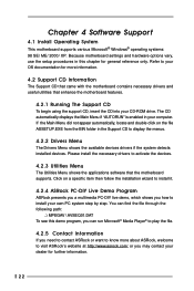
...necessary drivers to visit ASRock's website at http://www.asrock.com; or you need to contact ASRock or want to know more information. 4.2 Support CD Information The Support CD that came with the motherboard contains necessary drivers and useful utilities that the motherboard supports. Refer to...file. 4.2.5 Contact Information If you may contact your dealer for more about ASRock, welcome to activate the devices. 4.2.3 Utilities Menu The Utilities Menu shows the applications software that enhance the motherboard features. 4.2.1 Running The Support CD To begin using the support CD, ...
...necessary drivers to visit ASRock's website at http://www.asrock.com; or you need to contact ASRock or want to know more information. 4.2 Support CD Information The Support CD that came with the motherboard contains necessary drivers and useful utilities that the motherboard supports. Refer to...file. 4.2.5 Contact Information If you may contact your dealer for more about ASRock, welcome to activate the devices. 4.2.3 Utilities Menu The Utilities Menu shows the applications software that enhance the motherboard features. 4.2.1 Running The Support CD To begin using the support CD, ...
User Manual
Page 23
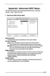
... Actual Frequency DRAM Frequency Flexibility Option Disabled Auto 133MHz Auto Disabled [ Setup Help ] to [Enabled]. 23 However, this motherboard determined by the jumper-setting. [Manual]: This allows user to set to select this option, which will introduce you the...detect the inserted memory module(s) and automatically assign appropriate frequency. CPU Host Frequency: [Auto]: It is recommended to [Auto], the motherboard will allow better tolerance for better system stability. Advanced BIOS Setup Menu Main Advanced AMIBIOS SETUP UTILITY - Flexibility Option: The default value...
... Actual Frequency DRAM Frequency Flexibility Option Disabled Auto 133MHz Auto Disabled [ Setup Help ] to [Enabled]. 23 However, this motherboard determined by the jumper-setting. [Manual]: This allows user to set to select this option, which will introduce you the...detect the inserted memory module(s) and automatically assign appropriate frequency. CPU Host Frequency: [Auto]: It is recommended to [Auto], the motherboard will allow better tolerance for better system stability. Advanced BIOS Setup Menu Main Advanced AMIBIOS SETUP UTILITY - Flexibility Option: The default value...
User Manual
Page 26
... AC'97 Audio: Select [Disabled], [Auto] or [Enabled] for Game Port or disable Game Port. It allows you to monitor the parameters for CPU temperature, Motherboard temperature, CPU fan speed, and critical voltage.
... AC'97 Audio: Select [Disabled], [Auto] or [Enabled] for Game Port or disable Game Port. It allows you to monitor the parameters for CPU temperature, Motherboard temperature, CPU fan speed, and critical voltage.
Quick Installation Guide
Page 1
... warranties or conditions of merchantability or fitness for loss of profits, loss of business, loss of data, interruption of business and the like), even if ASRock has been advised of the possibility of such damages arising from any defect or error in this guide are used only for identification or explanation... use only and subject to change without notice, and should not be constructed as a commitment by the purchaser for backup purpose, without written consent of ASRock Inc. This device complies with Part 15 of the FCC Rules. All rights reserved. 1 ASRock K7VM3 Motherboard English
... warranties or conditions of merchantability or fitness for loss of profits, loss of business, loss of data, interruption of business and the like), even if ASRock has been advised of the possibility of such damages arising from any defect or error in this guide are used only for identification or explanation... use only and subject to change without notice, and should not be constructed as a commitment by the purchaser for backup purpose, without written consent of ASRock Inc. This device complies with Part 15 of the FCC Rules. All rights reserved. 1 ASRock K7VM3 Motherboard English
Quick Installation Guide
Page 2
Motherboard Layout English 1 PS2_USB_PWR1 jumper 3 CPU fan connector (CPU_FAN1) 5 North Bridge controller 7 ATX power connector (ATXPWR1) 9 Secondary IDE connector (IDE2, Black) 11 AGP slot (AGP1) 13 ... 2.0 header (USB45, Blue) 22 AMR slot (AMR1) 24 JL1 jumper 26 Front panel audio connector (AUDIO1) 28 AUDIO CODEC 30 Internal audio connector: AUX1 (White) 2 ASRock K7VM3 Motherboard
Motherboard Layout English 1 PS2_USB_PWR1 jumper 3 CPU fan connector (CPU_FAN1) 5 North Bridge controller 7 ATX power connector (ATXPWR1) 9 Secondary IDE connector (IDE2, Black) 11 AGP slot (AGP1) 13 ... 2.0 header (USB45, Blue) 22 AMR slot (AMR1) 24 JL1 jumper 26 Front panel audio connector (AUDIO1) 28 AUDIO CODEC 30 Internal audio connector: AUX1 (White) 2 ASRock K7VM3 Motherboard
Quick Installation Guide
Page 3
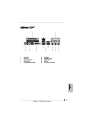
ASRock I/OTM 1 Parallel port 3 Game port 5 Line In (Light Blue) 7 USB 2.0 ports 9 PS/2 keyboard port (Purple) 2 RJ-45 port 4 Microphone (Pink) 6 Line Out (Lime) 8 VGA port 10 PS/2 mouse port (Green) English 3 ASRock K7VM3 Motherboard
ASRock I/OTM 1 Parallel port 3 Game port 5 Line In (Light Blue) 7 USB 2.0 ports 9 PS/2 keyboard port (Purple) 2 RJ-45 port 4 Microphone (Pink) 6 Line Out (Lime) 8 VGA port 10 PS/2 mouse port (Green) English 3 ASRock K7VM3 Motherboard
Quick Installation Guide
Page 4
.... IDE2: ATA 133 / Ultra DMA Mode 6; Chassis fan tachometer PCI slots: 2 slots with robust design conforming to ASRock's commitment to protect CPU life (ASRock U-COP)(see CAUTION 2) AMR slot: 1 slot, supports AMR modem card English 4 ASRock K7VM3 Motherboard It delivers excellent performance with PCI Specification 2.2 AGP slot: 1 AGP slot, supports 1.5V, 4X AGP card (see...
.... IDE2: ATA 133 / Ultra DMA Mode 6; Chassis fan tachometer PCI slots: 2 slots with robust design conforming to ASRock's commitment to protect CPU life (ASRock U-COP)(see CAUTION 2) AMR slot: 1 slot, supports AMR modem card English 4 ASRock K7VM3 Motherboard It delivers excellent performance with PCI Specification 2.2 AGP slot: 1 AGP slot, supports 1.5V, 4X AGP card (see...
Quick Installation Guide
Page 5
...; 98/ ME. Please refer to Microsoft® official document at http://www.microsoft.com/whdc/hwdev/bus/USB/USB2support.mspx 4. English 5 ASRock K7VM3 Motherboard Audio Jack: Line Out / Line In / Microphone + Game port AMI legal BIOS; Supports "Plug and Play"; It may not work... will also be overclocked proportionally. SMBIOS 2.3.1 support; Although K7VM3 offers stepless control, it is set of K7VM3 is not recommended to perform over clocking, other than the recommended CPU bus frequencies may cause permanent damage! 3. USB 2.0: ASRock I/OTM: BIOS: OS: 4 default USB 2.0 ports and...
...; 98/ ME. Please refer to Microsoft® official document at http://www.microsoft.com/whdc/hwdev/bus/USB/USB2support.mspx 4. English 5 ASRock K7VM3 Motherboard Audio Jack: Line Out / Line In / Microphone + Game port AMI legal BIOS; Supports "Plug and Play"; It may not work... will also be overclocked proportionally. SMBIOS 2.3.1 support; Although K7VM3 offers stepless control, it is set of K7VM3 is not recommended to perform over clocking, other than the recommended CPU bus frequencies may cause permanent damage! 3. USB 2.0: ASRock I/OTM: BIOS: OS: 4 default USB 2.0 ports and...
Quick Installation Guide
Page 6
..., place it firmly on the carpet or the like. Step 3. Step 4. For proper installation, please kindly refer to the motherboard, peripherals, and/or components. 2. Also remember to a 90° angle. English 6 ASRock K7VM3 Motherboard Hold components by lifting the lever up to use a grounded wrist strap or touch a safety grounded object before touching any...
..., place it firmly on the carpet or the like. Step 3. Step 4. For proper installation, please kindly refer to the motherboard, peripherals, and/or components. 2. Also remember to a 90° angle. English 6 ASRock K7VM3 Motherboard Hold components by lifting the lever up to use a grounded wrist strap or touch a safety grounded object before touching any...

