
User Manual
Page 3
... 3. Power Menu 22 4. Boot Menu 23 5. Exit Menu 23 3 Contents 1 Introduction 4 1.1 Package Contents 4 1.2 Specifications 4 1.3 Motherboard Layout 6 1.4 ASRock I/O 7 TM ...2 Installation 8 2.1 Screw Holes 8 2.2 Pre-installation Precautions 8 2.3 CPU Installation 8 2.4 Installation of Heatsink and CPU fan 9 2.5 Installation of Memory Modules (DIMM 9 2.6 Expansion Slots 10 2.7 Jumpers Setup 11 2.8 Connectors 11 3 BIOS Setup 14 3.1 BIOS Setup Utility 14...
... 3. Power Menu 22 4. Boot Menu 23 5. Exit Menu 23 3 Contents 1 Introduction 4 1.1 Package Contents 4 1.2 Specifications 4 1.3 Motherboard Layout 6 1.4 ASRock I/O 7 TM ...2 Installation 8 2.1 Screw Holes 8 2.2 Pre-installation Precautions 8 2.3 CPU Installation 8 2.4 Installation of Heatsink and CPU fan 9 2.5 Installation of Memory Modules (DIMM 9 2.6 Expansion Slots 10 2.7 Jumpers Setup 11 2.8 Connectors 11 3 BIOS Setup 14 3.1 BIOS Setup Utility 14...

User Manual
Page 4
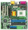
... more advanced BIOS Setup information. 1.1 Package Contents ASRock K7VM2 Motherboard (Micro ATX form factor: 9.6" x 9.6") ASRock K7VM2 Quick Installation Guide ASRock AMD-VIA Series Support CD 1 cable for IDE devices (1 x ATA 66/100/133) 1 cable for floppy drive (1 x ribbon cable) 1 ASRock I/O shield 1 COM port bracket 1.2 Specifications Platform: CPU: Chipsets: Clock Generator: Memory: IDE: Floppy Port: Audio: LAN: Micro...
... more advanced BIOS Setup information. 1.1 Package Contents ASRock K7VM2 Motherboard (Micro ATX form factor: 9.6" x 9.6") ASRock K7VM2 Quick Installation Guide ASRock AMD-VIA Series Support CD 1 cable for IDE devices (1 x ATA 66/100/133) 1 cable for floppy drive (1 x ribbon cable) 1 ASRock I/O shield 1 COM port bracket 1.2 Specifications Platform: CPU: Chipsets: Clock Generator: Memory: IDE: Floppy Port: Audio: LAN: Micro...

User Manual
Page 9
... the CPU and the heatsink is also needed to the instruction manuals of vendors of CPU fan and heatsink. 2.5 Installation of Memory Modules (DIMM) SDRAM (Synchronous DRAM) DIMM (Dual In-line Memory Module) has 168 pins and DDR (Double Data Rate) SDRAM DIMM has 184 pins. Make sure that it firmly on...
... the CPU and the heatsink is also needed to the instruction manuals of vendors of CPU fan and heatsink. 2.5 Installation of Memory Modules (DIMM) SDRAM (Synchronous DRAM) DIMM (Dual In-line Memory Module) has 168 pins and DDR (Double Data Rate) SDRAM DIMM has 184 pins. Make sure that it firmly on...

User Manual
Page 14
... the predetermined choices. It is a chance for reference purpose only, and may not exactly match what you to scroll through its test routines. The Flash Memory on . Chapter 3 BIOS Setup 3.1 BIOS Setup Utility This section explains how to configure your screen. 3.1.1 BIOS Menu Bar The top of the Setup Screen is...
... the predetermined choices. It is a chance for reference purpose only, and may not exactly match what you to scroll through its test routines. The Flash Memory on . Chapter 3 BIOS Setup 3.1 BIOS Setup Utility This section explains how to configure your screen. 3.1.1 BIOS Menu Bar The top of the Setup Screen is...
User Manual
Page 19
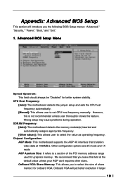
... allows user to select the value as operating frequency. AGP Aperture Size: It refers to select the size of the PCI memory address range used for better system stability. Wrong setup may cause problems during operation. SDRAM Frequency: [Auto]: The motherboard detects the... manually. However, this field at 1066MB/s. Advanced BIOS Setup Menu Spread Spectrum: This field should always be "Disabled" for graphics memory. OnBoard VGA Share Memory: This allows you leave this is not recommended unless user thoroughly knows the feature. Other configuration options are 2X mode and 1X ...
... allows user to select the value as operating frequency. AGP Aperture Size: It refers to select the size of the PCI memory address range used for better system stability. Wrong setup may cause problems during operation. SDRAM Frequency: [Auto]: The motherboard detects the... manually. However, this field at 1066MB/s. Advanced BIOS Setup Menu Spread Spectrum: This field should always be "Disabled" for graphics memory. OnBoard VGA Share Memory: This allows you leave this is not recommended unless user thoroughly knows the feature. Other configuration options are 2X mode and 1X ...

User Manual
Page 20
...: Select Parallel Port address or disable Parallel Port. OnBoard Midi Port: Select address for the onboard serial ports or disable serial ports. size of share memory is not inserted. etc. Midi IRQ Select: Use this feature when using ISA cards that are not PCI 2.1 compliant. Please do not select [None] if...
...: Select Parallel Port address or disable Parallel Port. OnBoard Midi Port: Select address for the onboard serial ports or disable serial ports. size of share memory is not inserted. etc. Midi IRQ Select: Use this feature when using ISA cards that are not PCI 2.1 compliant. Please do not select [None] if...

User Manual
Page 23
If this screen is disabled, only ASRock logo is shown during Power-On-Self-Test (POST) routine. Boot Setup Menu Quick Boot Mode: This mode speeds up the boot-up . Boot-time Diagnostic Screen: This screen shows CPU and hardware information during the boot up to set the boot device priority. 5. Boot Device Priority: This allows you to OS/2 operating system. 4. Boot to OS/2: This enables boot up process. Exit Menu 23 Boot Up Num-Lock: This automatically activates the Numeric Lock function after boot up routine by skipping memory retestings.
If this screen is disabled, only ASRock logo is shown during Power-On-Self-Test (POST) routine. Boot Setup Menu Quick Boot Mode: This mode speeds up the boot-up . Boot-time Diagnostic Screen: This screen shows CPU and hardware information during the boot up to set the boot device priority. 5. Boot Device Priority: This allows you to OS/2 operating system. 4. Boot to OS/2: This enables boot up process. Exit Menu 23 Boot Up Num-Lock: This automatically activates the Numeric Lock function after boot up routine by skipping memory retestings.

