
User Manual
Page 3
...Expansion Slots (PCI and AGP Slots 14 2.5 Jumpers Setup 15 2.6 Onboard Headers and Connectors 17 2.7 Serial ATA (SATA) Hard Disks Installation 20 2.8 Hot Plug and Hot Swap Functions for SATA HDDs ....... 20 2.9 Making An SATA Driver Diskette 21 3. BIOS SETUP UTILITY 22 3.1 Introduction 22 3.1.1 BIOS Menu Bar 22 3.1.2 Navigation Keys 23 ...33 3.5.1 Boot Settings Configuration 34 3.5.2 Boot Device Priority 34 3.6 Security Screen 35 3.7 Exit Screen 36 3 Contents 1. Introduction 5 1.1 Package Contents 5 1.2 Specifications 6 1.3 Motherboard Layout 8 1.4 ASRock I/O Plus 9 TM 2.
...Expansion Slots (PCI and AGP Slots 14 2.5 Jumpers Setup 15 2.6 Onboard Headers and Connectors 17 2.7 Serial ATA (SATA) Hard Disks Installation 20 2.8 Hot Plug and Hot Swap Functions for SATA HDDs ....... 20 2.9 Making An SATA Driver Diskette 21 3. BIOS SETUP UTILITY 22 3.1 Introduction 22 3.1.1 BIOS Menu Bar 22 3.1.2 Navigation Keys 23 ...33 3.5.1 Boot Settings Configuration 34 3.5.2 Boot Device Priority 34 3.6 Security Screen 35 3.7 Exit Screen 36 3 Contents 1. Introduction 5 1.1 Package Contents 5 1.2 Specifications 6 1.3 Motherboard Layout 8 1.4 ASRock I/O Plus 9 TM 2.

User Manual
Page 5
...SATA) Data Cable One Serial ATA (SATA) HDD Power Cable(Optional) One ASRock I/O PlusTM Shield 5 In this manual occur, the updated version will be available on ASRock website as well. You may find the latest memory and CPU support lists on ASRock website without notice. ASRock website http://www.asrock.com 1.1 Package Contents ASRock K7V88... Motherboard (ATX Form Factor: 12.0-in x 8.0-in, 30.5 cm x 20.3 cm) ASRock K7V88 Quick Installation Guide ASRock K7V88 Support CD One ...
...SATA) Data Cable One Serial ATA (SATA) HDD Power Cable(Optional) One ASRock I/O PlusTM Shield 5 In this manual occur, the updated version will be available on ASRock website as well. You may find the latest memory and CPU support lists on ASRock website without notice. ASRock website http://www.asrock.com 1.1 Package Contents ASRock K7V88... Motherboard (ATX Form Factor: 12.0-in x 8.0-in, 30.5 cm x 20.3 cm) ASRock K7V88 Quick Installation Guide ASRock K7V88 Support CD One ...

User Manual
Page 6
... AMD AthlonTM / AthlonTM XP / DuronTM processor Chipsets: North Bridge: VIA KT880, FSB @ 400 MHz South Bridge: VIA VT8237, supports USB 2.0, ATA 133, SATA 1.5Gb/s Memory: 4 DDR DIMM Slots: DDR1, DDR2, DDR3, and DDR4 Support PC3200 (DDR400) / PC2700 (DDR333) / PC2100 (DDR266), Max. 4GB Dual... 8 USB 2.0 ports: include 6 ready-to-use USB 2.0 ports on the rear panel, plus one on-board header supporting 2 extra USB 2.0 ports (see CAUTION 4) ASRock I/O PlusTM: 1 PS/2 mouse port, 1 PS/2 keyboard port, 1 serial port: COM1, 1 parallel port: ECP/EPP support, 6 ready-to-use USB 2.0 ports,...
... AMD AthlonTM / AthlonTM XP / DuronTM processor Chipsets: North Bridge: VIA KT880, FSB @ 400 MHz South Bridge: VIA VT8237, supports USB 2.0, ATA 133, SATA 1.5Gb/s Memory: 4 DDR DIMM Slots: DDR1, DDR2, DDR3, and DDR4 Support PC3200 (DDR400) / PC2700 (DDR333) / PC2100 (DDR266), Max. 4GB Dual... 8 USB 2.0 ports: include 6 ready-to-use USB 2.0 ports on the rear panel, plus one on-board header supporting 2 extra USB 2.0 ports (see CAUTION 4) ASRock I/O PlusTM: 1 PS/2 mouse port, 1 PS/2 keyboard port, 1 serial port: COM1, 1 parallel port: ECP/EPP support, 6 ready-to-use USB 2.0 ports,...

User Manual
Page 8
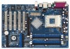
... 2.0 T: USB2 B: USB3 USB 2.0 T: USB0 Top: RJ-45 B: USB1 USB 2.0 T: USB4 1 B: USB5 USB45 CD1 AUX1 ATXPWR1 VKIACT8h8ip0set AGP 8X SATA Audio CODEC JR1 JL1 1 AUDIO1 1.5V_AGP1 LAN PHY PCI 1 ` IDE2 FSB_SEL0 1 1 FSB_SEL1 Super I/O PCI 2 K7V88 FSB400 2MB BIOS 1 GAME1 PCI 3 USB2.0 5.1 CH PCI 4 ATA133 DDR400 PCI 5 IR1 1 IDE1 VIA VT8237 SATA2 SATA1 FLOPPY1...
... 2.0 T: USB2 B: USB3 USB 2.0 T: USB0 Top: RJ-45 B: USB1 USB 2.0 T: USB4 1 B: USB5 USB45 CD1 AUX1 ATXPWR1 VKIACT8h8ip0set AGP 8X SATA Audio CODEC JR1 JL1 1 AUDIO1 1.5V_AGP1 LAN PHY PCI 1 ` IDE2 FSB_SEL0 1 1 FSB_SEL1 Super I/O PCI 2 K7V88 FSB400 2MB BIOS 1 GAME1 PCI 3 USB2.0 5.1 CH PCI 4 ATA133 DDR400 PCI 5 IR1 1 IDE1 VIA VT8237 SATA2 SATA1 FLOPPY1...

User Manual
Page 17
..., see p.8, No. 13) (39-pin IDE2, see p.8, No. 15) SATA2 SATA1 These two Serial ATA (SATA) connectors support SATA data cables for the details. Please refer to the instruction of the SATA data cable can be connected to the IDE devices 80-conductor ATA 66/100/133 cable Note: If...) (SATA2: see p.8, No. 12) PIN1 IDE1 PIN1 IDE2 connect the blue end to the motherboard connect the black end to the SATA hard disk or the SATA connector on this motherboard, please set the IDE device as "Master". Besides, to optimize compatibility and performance, please connect your IDE device ...
..., see p.8, No. 13) (39-pin IDE2, see p.8, No. 15) SATA2 SATA1 These two Serial ATA (SATA) connectors support SATA data cables for the details. Please refer to the instruction of the SATA data cable can be connected to the IDE devices 80-conductor ATA 66/100/133 cable Note: If...) (SATA2: see p.8, No. 12) PIN1 IDE1 PIN1 IDE2 connect the blue end to the motherboard connect the black end to the SATA hard disk or the SATA connector on this motherboard, please set the IDE device as "Master". Besides, to optimize compatibility and performance, please connect your IDE device ...

User Manual
Page 18
... cable to the power connector of SATA power cable to the power connector on the rear panel. Shared USB 2.0 Header (9-pin USB45) (see p.8, No. 22) USB_PWR P-7 P+7 GND DUMMY 1 GND P+6 P-6 USB_PWR ASRock I/O PlusTM provides you to receive stereo audio input from sound sources such as a CD...-ROM, DVD-ROM, TV tuner card, or MPEG card. O U T- Serial ATA (SATA) Power Cable (Optional) connect to the SATA HDD power connector connect to the power supply Please ...
... cable to the power connector of SATA power cable to the power connector on the rear panel. Shared USB 2.0 Header (9-pin USB45) (see p.8, No. 22) USB_PWR P-7 P+7 GND DUMMY 1 GND P+6 P-6 USB_PWR ASRock I/O PlusTM provides you to receive stereo audio input from sound sources such as a CD...-ROM, DVD-ROM, TV tuner card, or MPEG card. O U T- Serial ATA (SATA) Power Cable (Optional) connect to the SATA HDD power connector connect to the power supply Please ...
User Manual
Page 20
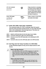
..., please note that it cannot perform Hot Plug if the OS has been installed into the drive bays of the SATA data cable to the SATA hard disk. 2.8 Hot Plug and Hot Swap Functions for SATA HDDs K7V88 motherboard supports Hot Plug and Hot Swap functions for the action to insert and remove the... SATA HDDs while the system is still power-on and in working condition. What is Hot Plug Function? Please connect a 3-pin power LED cable to ...
..., please note that it cannot perform Hot Plug if the OS has been installed into the drive bays of the SATA data cable to the SATA hard disk. 2.8 Hot Plug and Hot Swap Functions for SATA HDDs K7V88 motherboard supports Hot Plug and Hot Swap functions for the action to insert and remove the... SATA HDDs while the system is still power-on and in working condition. What is Hot Plug Function? Please connect a 3-pin power LED cable to ...

User Manual
Page 21
Please refer to the document in the Support CD, "Guide to VIA RAID Tool", which is located in Windows environment. STEP 1: Insert the ASRock Support CD into your optical drive to boot your system. (Do NOT insert any floppy diskette into the floppy drive, and press . WARNING! Start to ... or Windows XP on your system, or you may also set RAID 0 / RAID 1 / JBOD configuration before you start to format the floppy diskette and copy SATA drivers into the floppy diskette. STEP 3: When you see the message on the screen, "Do you will see these messages, Please insert a diskette into the...
Please refer to the document in the Support CD, "Guide to VIA RAID Tool", which is located in Windows environment. STEP 1: Insert the ASRock Support CD into your optical drive to boot your system. (Do NOT insert any floppy diskette into the floppy drive, and press . WARNING! Start to ... or Windows XP on your system, or you may also set RAID 0 / RAID 1 / JBOD configuration before you start to format the floppy diskette and copy SATA drivers into the floppy diskette. STEP 3: When you see the message on the screen, "Do you will see these messages, Please insert a diskette into the...
