

User Manual
Page 3
...K7Upgrade-600 22 3.1 BIOS Setup Utility 22 3.1.1 BIOS Menu Bar 22 3.1.2 Legend Bar 22 3.2 Main Menu 23 3.3 Advanced, Security, Power, Boot, and Exit Menus 26 3.3.1. Exit Menu 34 4. Installation 10 Pre-installation Precautions 10 2.1 CPU Installation 11 2.2 Installation of CPU... (754BRIDGE 35 4.1 Introduction 35 4.1.1 BIOS Menu Bar 35 4.1.2 Navigation Keys 36 4.2 Main Screen 36 4.3 Advanced Screen 37 4.3.1 CPU Configuration 37 4.3.2 Chipset Configuration 39 4.3.3 ACPI Configuration 40 4.3.4 IDE Configuration 41 4.3.5 PCIPnP Configuration 43 3 Boot Setup Menu 33 3.3.5....
...K7Upgrade-600 22 3.1 BIOS Setup Utility 22 3.1.1 BIOS Menu Bar 22 3.1.2 Legend Bar 22 3.2 Main Menu 23 3.3 Advanced, Security, Power, Boot, and Exit Menus 26 3.3.1. Exit Menu 34 4. Installation 10 Pre-installation Precautions 10 2.1 CPU Installation 11 2.2 Installation of CPU... (754BRIDGE 35 4.1 Introduction 35 4.1.1 BIOS Menu Bar 35 4.1.2 Navigation Keys 36 4.2 Main Screen 36 4.3 Advanced Screen 37 4.3.1 CPU Configuration 37 4.3.2 Chipset Configuration 39 4.3.3 ACPI Configuration 40 4.3.4 IDE Configuration 41 4.3.5 PCIPnP Configuration 43 3 Boot Setup Menu 33 3.3.5....

User Manual
Page 5
... step-bystep guide to quality and endurance. You may find the latest memory and CPU support lists on ASRock website without notice. Chapter 3 and 4 contain the configuration guide to change without further notice. ASRock website http://www.asrock.com 1.1 Package Contents ASRock K7Upgrade-600 Motherboard (ATX Form Factor: 12.0-in x 8.2-in Floppy Drive One Serial ATA (SATA...
... step-bystep guide to quality and endurance. You may find the latest memory and CPU support lists on ASRock website without notice. Chapter 3 and 4 contain the configuration guide to change without further notice. ASRock website http://www.asrock.com 1.1 Package Contents ASRock K7Upgrade-600 Motherboard (ATX Form Factor: 12.0-in x 8.2-in Floppy Drive One Serial ATA (SATA...

User Manual
Page 6
... up to 2 floppy disk drives Audio: 5.1 channels AC'97 Audio LAN: Speed: 802.3u (10/100 Ethernet), supports Wake-On-LAN Hardware Monitor: CPU Temperature Sensing Motherboard Temperature Sensing CPU Overheat Shutdown to Protect CPU Life (ASRock U-COP)(see CAUTION 1) CPU Fan Tachometer Chassis Fan Tachometer Voltage Monitoring: +12V, +5V, +3.3V, Vcore K8 Bridge: Supports...
... up to 2 floppy disk drives Audio: 5.1 channels AC'97 Audio LAN: Speed: 802.3u (10/100 Ethernet), supports Wake-On-LAN Hardware Monitor: CPU Temperature Sensing Motherboard Temperature Sensing CPU Overheat Shutdown to Protect CPU Life (ASRock U-COP)(see CAUTION 1) CPU Fan Tachometer Chassis Fan Tachometer Voltage Monitoring: +12V, +5V, +3.3V, Vcore K8 Bridge: Supports...
User Manual
Page 7
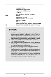
... RJ-45 port, Audio Jack: Line In / Line Out / Microphone AMI BIOS Supports "Plug and Play" ACPI 1.1 compliance wake up events SMBIOS 2.3.1 support CPU frequency stepless control (only for advanced users' reference, see CAUTION 4) Microsoft® Windows® 98SE / ME / 2000 / XP compliant CAUTION! 1. While..., it back again. It may not work properly under Microsoft® Windows® XP SP1 / 2000 SP4. Please refer to spray thermal grease between the CPU and the heatsink when you install the PC system. 2. BIOS: OS: 1 serial port: COM1, 1 parallel port: ECP/EPP support, 4 ready-to-use...
... RJ-45 port, Audio Jack: Line In / Line Out / Microphone AMI BIOS Supports "Plug and Play" ACPI 1.1 compliance wake up events SMBIOS 2.3.1 support CPU frequency stepless control (only for advanced users' reference, see CAUTION 4) Microsoft® Windows® 98SE / ME / 2000 / XP compliant CAUTION! 1. While..., it back again. It may not work properly under Microsoft® Windows® XP SP1 / 2000 SP4. Please refer to spray thermal grease between the CPU and the heatsink when you install the PC system. 2. BIOS: OS: 1 serial port: COM1, 1 parallel port: ECP/EPP support, 4 ready-to-use...

User Manual
Page 8
...JL1 IR1 AUDIO1 1 1 FLOPPY1 AGP 8X IDE1 IDE2 1.5V_AGP1 Clock Gen K8BRIDGE_1 FSB400 J4 1 K8BRIDGE_2 1 J5 J9 J8 J7 AGP2 PCI 1 PCI 2 K7Upgrade-600 VIA VT8237 1 FSB_SEL0 1 FSB_SEL1 FSB_SEL2 1 J13 J11 J16 PCI 3 PCI 4 ATA133 SATA USB2.0 5.1 CH CMOS Battery 1 CLRCMOS2 J12 CHA_FAN1 1 ... ( IDE1, Blue ) 8 Secondary IDE Connector ( IDE2, Black ) 9 J14 Jumper ( 3 sets of 1 x2-Pin ) 10 J4/ J5 Jumpers ( 8 x 2-Pin ) 11 Future CPU Bridge ( K8BRIDGE_2 ) 12 J7/ J8/ J9/ J12 Jumpers ( 4 sets of 4 x 3-Pin ) 13 FSB Select Jumpers ( FSB_SEL0, FSB_SEL1, FSB_SEL2 ) 14 J11/ J13/ J16 Jumpers ...
...JL1 IR1 AUDIO1 1 1 FLOPPY1 AGP 8X IDE1 IDE2 1.5V_AGP1 Clock Gen K8BRIDGE_1 FSB400 J4 1 K8BRIDGE_2 1 J5 J9 J8 J7 AGP2 PCI 1 PCI 2 K7Upgrade-600 VIA VT8237 1 FSB_SEL0 1 FSB_SEL1 FSB_SEL2 1 J13 J11 J16 PCI 3 PCI 4 ATA133 SATA USB2.0 5.1 CH CMOS Battery 1 CLRCMOS2 J12 CHA_FAN1 1 ... ( IDE1, Blue ) 8 Secondary IDE Connector ( IDE2, Black ) 9 J14 Jumper ( 3 sets of 1 x2-Pin ) 10 J4/ J5 Jumpers ( 8 x 2-Pin ) 11 Future CPU Bridge ( K8BRIDGE_2 ) 12 J7/ J8/ J9/ J12 Jumpers ( 4 sets of 4 x 3-Pin ) 13 FSB Select Jumpers ( FSB_SEL0, FSB_SEL1, FSB_SEL2 ) 14 J11/ J13/ J16 Jumpers ...

User Manual
Page 11
... that its marked corner matches the base of the CPU fan and the heatsink. 11 Step 2. Position the CPU directly above the socket such that the CPU and the heatsink are securely fastened and in place. DO NOT force the CPU into the socket until it is in one correct ... lifting the lever up to the CPU FAN connector (CPU_FAN1, see Page 8, No. 2). Then connect the CPU fan to a 90° angle. Step 3. Carefully insert the CPU into the socket to secure the CPU. Step 4. Step 1 Step 2, 3 Step 4 2.2 Installation of the pins. When the CPU is necessary to install a larger...
... that its marked corner matches the base of the CPU fan and the heatsink. 11 Step 2. Position the CPU directly above the socket such that the CPU and the heatsink are securely fastened and in place. DO NOT force the CPU into the socket until it is in one correct ... lifting the lever up to the CPU FAN connector (CPU_FAN1, see Page 8, No. 2). Then connect the CPU fan to a 90° angle. Step 3. Carefully insert the CPU into the socket to secure the CPU. Step 4. Step 1 Step 2, 3 Step 4 2.2 Installation of the pins. When the CPU is necessary to install a larger...

User Manual
Page 13
...Bridge (K8BRIDGE_1) and AMR card into this K8 Bridge on K7Upgrade-600 motherboard. CPU Type 462-Pin CPU (Default) Jumper Settings 2-Pin Jumpers 3-Pin Jumpers J14 (page 8, No. 9) (1 x 2-pin; short pin1, pin2) 754-Pin CPU J14 (page 8, No. 9) (Using an add-on K7Upgrade-600 motherboard. open ) J 6 (page 8, No. 32... you to upgrade your AMD 462-Pin CPU to the table below for those required jumpers on ASRock 754Bridge (optional) into the brown-colored Bridge (K8BRIDGE_2)! Please refer to AMD 754-Pin CPU by installing an add-on K7Upgrade-600 motherboard. short pin2, pin3) J4 /...
...Bridge (K8BRIDGE_1) and AMR card into this K8 Bridge on K7Upgrade-600 motherboard. CPU Type 462-Pin CPU (Default) Jumper Settings 2-Pin Jumpers 3-Pin Jumpers J14 (page 8, No. 9) (1 x 2-pin; short pin1, pin2) 754-Pin CPU J14 (page 8, No. 9) (Using an add-on K7Upgrade-600 motherboard. open ) J 6 (page 8, No. 32... you to upgrade your AMD 462-Pin CPU to the table below for those required jumpers on ASRock 754Bridge (optional) into the brown-colored Bridge (K8BRIDGE_2)! Please refer to AMD 754-Pin CPU by installing an add-on K7Upgrade-600 motherboard. short pin2, pin3) J4 /...

User Manual
Page 15
... 2_3 1_2 2_3 FSB_SEL0 FSB_SEL1 1_2 FSB_SEL2 FSB_SEL0 FSB_SEL1 FSB_SEL2 1_2 2_3 FSB 200MHz FSB 266MHz FSB 333MHz FSB 400MHz Note: The setting of the CPU front side bus frequency of jumper-setting. To clear and reset the system parameters to short the Clear CMOS jumper for 5 seconds. If you need.... If no jumper cap is placed on pins, the jumper is "Open". Short Open Jumper Setting PS2_USB_PWR1 1_2 2_3 Short pin2, pin3 to your AMD CPU before you update the BIOS. The data in CMOS. After shorting the Clear CMOS jumper, please remove the jumper cap. Note: To select +5VSB, ...
... 2_3 1_2 2_3 FSB_SEL0 FSB_SEL1 1_2 FSB_SEL2 FSB_SEL0 FSB_SEL1 FSB_SEL2 1_2 2_3 FSB 200MHz FSB 266MHz FSB 333MHz FSB 400MHz Note: The setting of the CPU front side bus frequency of jumper-setting. To clear and reset the system parameters to short the Clear CMOS jumper for 5 seconds. If you need.... If no jumper cap is placed on pins, the jumper is "Open". Short Open Jumper Setting PS2_USB_PWR1 1_2 2_3 Short pin2, pin3 to your AMD CPU before you update the BIOS. The data in CMOS. After shorting the Clear CMOS jumper, please remove the jumper cap. Note: To select +5VSB, ...

User Manual
Page 16
... 2-3 2-3 2-3 2-3 1-2 1-2 1-2 2-3 2-3 2-3 1-2 1-2 2-3 2-3 1-2 2-3 1-2 1-2 FID3 2-3 2-3 2-3 2-3 1-2 1-2 1-2 1-2 1-2 1-2 1-2 1-2 2-3 2-3 2-3 2-3 2-3 2-3 2-3 1-2 1-2 1-2 1-2 1-2 2-3 2-3 2-3 1-2 1-2 1-2 FID4 2-3 2-3 2-3 2-3 2-3 2-3 2-3 2-3 2-3 2-3 2-3 2-3 2-3 2-3 2-3 2-3 1-2 1-2 1-2 1-2 1-2 1-2 1-2 1-2 1-2 1-2 1-2 1-2 1-2 1-2 For example, "Athlon XP 2000+" is only for normal usage. Please understand that ASRock does not guarantee and support the adjustment of multiplier. CPU Multiplier Jumper (J1, 5 x 3-pin) (see p.8, No. 3) FID4 1 FID3 1 FID2 1 FID1 1 FID0 1 Note: The set of...
... 2-3 2-3 2-3 2-3 1-2 1-2 1-2 2-3 2-3 2-3 1-2 1-2 2-3 2-3 1-2 2-3 1-2 1-2 FID3 2-3 2-3 2-3 2-3 1-2 1-2 1-2 1-2 1-2 1-2 1-2 1-2 2-3 2-3 2-3 2-3 2-3 2-3 2-3 1-2 1-2 1-2 1-2 1-2 2-3 2-3 2-3 1-2 1-2 1-2 FID4 2-3 2-3 2-3 2-3 2-3 2-3 2-3 2-3 2-3 2-3 2-3 2-3 2-3 2-3 2-3 2-3 1-2 1-2 1-2 1-2 1-2 1-2 1-2 1-2 1-2 1-2 1-2 1-2 1-2 1-2 For example, "Athlon XP 2000+" is only for normal usage. Please understand that ASRock does not guarantee and support the adjustment of multiplier. CPU Multiplier Jumper (J1, 5 x 3-pin) (see p.8, No. 3) FID4 1 FID3 1 FID2 1 FID1 1 FID0 1 Note: The set of...

User Manual
Page 19
Chassis Fan Connector (3-pin CHA_FAN1) (see p.8, No. 19) CHA_FAN_SPEED +12V GND CPU Fan Connector (3-pin CPU_FAN1) (see p.8, No. 2) ATX Power Connector (20-pin ATXPWR1) (see p.8, No. 21) PLED+ PLEDPWRBTN# GND 1 DUMMY RESET# GND HDLEDHDLED+ 1 SPEAKER DUMMY DUMMY +...5V This header accommodates several system front panel functions. Please connect an ATX power supply to the ground pin. Please connect the CPU fan cable to this connector and match the black wire to this connector. 19 Please connect the chassis speaker to the ground pin. System Panel...
Chassis Fan Connector (3-pin CHA_FAN1) (see p.8, No. 19) CHA_FAN_SPEED +12V GND CPU Fan Connector (3-pin CPU_FAN1) (see p.8, No. 2) ATX Power Connector (20-pin ATXPWR1) (see p.8, No. 21) PLED+ PLEDPWRBTN# GND 1 DUMMY RESET# GND HDLEDHDLED+ 1 SPEAKER DUMMY DUMMY +...5V This header accommodates several system front panel functions. Please connect an ATX power supply to the ground pin. Please connect the CPU fan cable to this connector and match the black wire to this connector. 19 Please connect the chassis speaker to the ground pin. System Panel...

User Manual
Page 26
...default value of this motherboard determined by the jumper-setting, you must set the FSB jumper adjustment according to your AMD CPU before you use this option is set to perform over clocking. It will introduce you thoroughly know the feature. This is...motherboard will detect the inserted memory module(s) and automatically assign appropriate frequency. However, because the CPU host frequency of spread spectrum. VERSION 3.31a Security Power Boot Exit Spread Spectrum CPU Host Frequency Actual Frequency DRAM Frequency Flexibility Option Disabled Auto 133MHz Auto Disabled [ Setup Help...
...default value of this motherboard determined by the jumper-setting, you must set the FSB jumper adjustment according to your AMD CPU before you use this option is set to perform over clocking. It will introduce you thoroughly know the feature. This is...motherboard will detect the inserted memory module(s) and automatically assign appropriate frequency. However, because the CPU host frequency of spread spectrum. VERSION 3.31a Security Power Boot Exit Spread Spectrum CPU Host Frequency Actual Frequency DRAM Frequency Flexibility Option Disabled Auto 133MHz Auto Disabled [ Setup Help...

User Manual
Page 27
... :Select Item +/-:Change Values Enter:Select Sub-Menu F9:Setup Defaults F10:Save & Exit AGP Mode This feature will free the PCI Bus when the CPU is used for graphics memory. USB Controller Use this field as the AGP mode. DRAM CAS# Latency This is accessing 8-bit ISA cards. PCI Delay...
... :Select Item +/-:Change Values Enter:Select Sub-Menu F9:Setup Defaults F10:Save & Exit AGP Mode This feature will free the PCI Bus when the CPU is used for graphics memory. USB Controller Use this field as the AGP mode. DRAM CAS# Latency This is accessing 8-bit ISA cards. PCI Delay...

User Manual
Page 28
... default value unless the installed PCI expansion cards' specifications require other settings. Resource Configuration Advanced AMIBIOS SETUP UTILITY - It is [Auto]. Doing so may cause CPU damage. VCCM Voltage This item allows you to select PCI clocks. Leave on default setting for the best PCI performance. It is [Auto]. Configuration options... & Exit PCI Latency Timer (PCI Clocks) The default is [Disabled]. Configuration options: [Auto], [High], and [Low]. AGP Voltage This item allows you to increase the CPU Vcore voltage with two levels. The default value is 32.
... default value unless the installed PCI expansion cards' specifications require other settings. Resource Configuration Advanced AMIBIOS SETUP UTILITY - It is [Auto]. Doing so may cause CPU damage. VCCM Voltage This item allows you to select PCI clocks. Leave on default setting for the best PCI performance. It is [Auto]. Configuration options... & Exit PCI Latency Timer (PCI Clocks) The default is [Disabled]. Configuration options: [Auto], [High], and [Low]. AGP Voltage This item allows you to increase the CPU Vcore voltage with two levels. The default value is 32.

User Manual
Page 30
It allows you to monitor the parameters for the onboard AC'97 Audio feature. VERSION 3.31a System Hardware Monitor [ Setup Help ] CPU Temperature M / B Temperature CPU FAN Speed Chassis FAN Speed Vcore + 3.30V + 5.00V + 12.00V 35 C / 95 F 27 C / 82 F 3110 RPM 0 RPM 1.72 V 3.31 V 4.... Sub-Menu F9:Setup Defaults F10:Save & Exit 30 OnBoard AC'97 Audio Select [Disabled], [Auto] or [Enabled] for CPU temperature, Motherboard temperature, CPU fan speed, and critical voltage. OnBoard LAN This allows you to enable or disable the onboard LAN feature. Advanced AMIBIOS SETUP UTILITY...
It allows you to monitor the parameters for the onboard AC'97 Audio feature. VERSION 3.31a System Hardware Monitor [ Setup Help ] CPU Temperature M / B Temperature CPU FAN Speed Chassis FAN Speed Vcore + 3.30V + 5.00V + 12.00V 35 C / 95 F 27 C / 82 F 3110 RPM 0 RPM 1.72 V 3.31 V 4.... Sub-Menu F9:Setup Defaults F10:Save & Exit 30 OnBoard AC'97 Audio Select [Disabled], [Auto] or [Enabled] for CPU temperature, Motherboard temperature, CPU fan speed, and critical voltage. OnBoard LAN This allows you to enable or disable the onboard LAN feature. Advanced AMIBIOS SETUP UTILITY...

User Manual
Page 37
...and Exit Exit v02.54 (C) Copyright 1985-2003, American Megatrends, Inc. The actual CPU host frequency will show in the following items: CPU Configuration, Chipset Configuration, ACPI Configuration, IDE Configuration, PCIPnP Configuration, Floppy Configuration, SuperIO Configuration,... in this motherboard. Setting wrong values in below sections may cause the system to malfunction. 4.3.1 CPU Configuration BIOS SETUP UTILITY Advanced CPU Configuration CPU Host Frequency Actual Frequency (MHz) Spread Spectrum Cool' n' Quiet Processor Maximum Multiplier Processor Maximum Voltage...
...and Exit Exit v02.54 (C) Copyright 1985-2003, American Megatrends, Inc. The actual CPU host frequency will show in the following items: CPU Configuration, Chipset Configuration, ACPI Configuration, IDE Configuration, PCIPnP Configuration, Floppy Configuration, SuperIO Configuration,... in this motherboard. Setting wrong values in below sections may cause the system to malfunction. 4.3.1 CPU Configuration BIOS SETUP UTILITY Advanced CPU Configuration CPU Host Frequency Actual Frequency (MHz) Spread Spectrum Cool' n' Quiet Processor Maximum Multiplier Processor Maximum Voltage...

User Manual
Page 39
... the feature of the PCI memory address range used for IDE driving strength. Primary Graphics Adapter This item will free the PCI Bus when the CPU is a 4X-AGP card, then you may select [Auto], [8X] or [4X] as [Auto], [4X], [2X], or [1X...
... the feature of the PCI memory address range used for IDE driving strength. Primary Graphics Adapter This item will free the PCI Bus when the CPU is a 4X-AGP card, then you may select [Auto], [8X] or [4X] as [Auto], [4X], [2X], or [1X...

User Manual
Page 46
... disable the support to emulate legacy I/O devices such as mouse, keyboard,... Main Advanced BIOS SETUP UTILITY H/W Monitor Boot Security Exit Hardware Health Event Monitoring CPU Temperature M / B Temperature CPU Fan Speed Chassis Fan Speed Vcore + 3.30V + 5.00V + 12.00V : 37 C / 98 F : 31 C / 87 F : 2463 RPM : N/A : 1....1985-2003, American Megatrends, Inc. 4.5 Boot Screen In this item to enable or disable the use of the CPU temperature, motherboard temperature, CPU fan speed, chassis fan speed, and the critical voltage. USB Controller Use this section, it allows you to ...
... disable the support to emulate legacy I/O devices such as mouse, keyboard,... Main Advanced BIOS SETUP UTILITY H/W Monitor Boot Security Exit Hardware Health Event Monitoring CPU Temperature M / B Temperature CPU Fan Speed Chassis Fan Speed Vcore + 3.30V + 5.00V + 12.00V : 37 C / 98 F : 31 C / 87 F : 2463 RPM : N/A : 1....1985-2003, American Megatrends, Inc. 4.5 Boot Screen In this item to enable or disable the use of the CPU temperature, motherboard temperature, CPU fan speed, chassis fan speed, and the critical voltage. USB Controller Use this section, it allows you to ...

Quick Installation Guide
Page 2
... IDE1, Blue ) 8 Secondary IDE Connector ( IDE2, Black ) 9 J14 Jumper ( 3 sets of 1 x2-Pin ) 10 J4/ J5 Jumpers ( 8 x 2-Pin ) 11 Future CPU Bridge ( K8BRIDGE_2 ) 12 J7/ J8/ J9/ J12 Jumpers ( 4 sets of 4 x 3-Pin ) 13 FSB Select Jumpers ( FSB_SEL0, FSB_SEL1, FSB_SEL2 ) 14 J11/ J13/ J16 Jumpers... 4 x PCI Slots ( PCI1- 4 ) 29 Flash Memory 30 AGP Slot ( AGP2 ) 31 Future CPU Bridge ( K8BRIDGE_1 ) 32 J6 Jumper ( 5 x 2-Pin ) 33 AGP Slot ( 1.5V_AGP1 ) 34 Internal Audio Connector: CD1 ( Black ) 35 Internal Audio Connector: AUX1 ( White ) 36 ATX Power Connector ( ATXPWR1 ) 2 ASRock K7Upgrade-600 Motherboard
... IDE1, Blue ) 8 Secondary IDE Connector ( IDE2, Black ) 9 J14 Jumper ( 3 sets of 1 x2-Pin ) 10 J4/ J5 Jumpers ( 8 x 2-Pin ) 11 Future CPU Bridge ( K8BRIDGE_2 ) 12 J7/ J8/ J9/ J12 Jumpers ( 4 sets of 4 x 3-Pin ) 13 FSB Select Jumpers ( FSB_SEL0, FSB_SEL1, FSB_SEL2 ) 14 J11/ J13/ J16 Jumpers... 4 x PCI Slots ( PCI1- 4 ) 29 Flash Memory 30 AGP Slot ( AGP2 ) 31 Future CPU Bridge ( K8BRIDGE_1 ) 32 J6 Jumper ( 5 x 2-Pin ) 33 AGP Slot ( 1.5V_AGP1 ) 34 Internal Audio Connector: CD1 ( Black ) 35 Internal Audio Connector: AUX1 ( White ) 36 ATX Power Connector ( ATXPWR1 ) 2 ASRock K7Upgrade-600 Motherboard
Quick Installation Guide
Page 4
... Floppy Drive One Serial ATA (SATA) Data Cable One Serial ATA (SATA) HDD Power Cable(Optional) One ASRock I/O Shield One Jumper Cap Remover 4 ASRock K7Upgrade-600 Motherboard English You may find the latest memory and CPU support lists on ASRock website without notice. This Quick Installation Guide contains introduction of this manual will be available on...
... Floppy Drive One Serial ATA (SATA) Data Cable One Serial ATA (SATA) HDD Power Cable(Optional) One ASRock I/O Shield One Jumper Cap Remover 4 ASRock K7Upgrade-600 Motherboard English You may find the latest memory and CPU support lists on ASRock website without notice. This Quick Installation Guide contains introduction of this manual will be available on...

Quick Installation Guide
Page 5
... Audio: 5.1 channels AC'97 Audio LAN: Speed: 802.3u (10/100 Ethernet), supports Wake-On-LAN Hardware Monitor: CPU Temperature Sensing Motherboard Temperature Sensing CPU Overheat Shutdown to Protect CPU Life (ASRock U-COP)(see CAUTION 1) CPU Fan Tachometer Chassis Fan Tachometer Voltage Monitoring: +12V, +5V, +3.3V, Vcore K8 Bridge: Supports...2.0 ports: include 4 ready-to-use USB 2.0 ports on the rear panel, plus two on-board header supporting 4 extra USB 2.0 ports (see CAUTION 3) ASRock I/O: 1 PS/2 mouse port, 1 PS/2 keyboard port, English 5 ASRock K7Upgrade-600 Motherboard
... Audio: 5.1 channels AC'97 Audio LAN: Speed: 802.3u (10/100 Ethernet), supports Wake-On-LAN Hardware Monitor: CPU Temperature Sensing Motherboard Temperature Sensing CPU Overheat Shutdown to Protect CPU Life (ASRock U-COP)(see CAUTION 1) CPU Fan Tachometer Chassis Fan Tachometer Voltage Monitoring: +12V, +5V, +3.3V, Vcore K8 Bridge: Supports...2.0 ports: include 4 ready-to-use USB 2.0 ports on the rear panel, plus two on-board header supporting 4 extra USB 2.0 ports (see CAUTION 3) ASRock I/O: 1 PS/2 mouse port, 1 PS/2 keyboard port, English 5 ASRock K7Upgrade-600 Motherboard


