

User Manual
Page 5
... (SATA) Data Cable One Serial ATA (SATA) HDD Power Cable(Optional) One ASRock I/O Shield One Jumper Cap Remover 5 1. ASRock website http://www.asrock.com 1.1 Package Contents ASRock K7Upgrade-600 Motherboard (ATX Form Factor: 12.0-in x 8.2-in, 30.5 cm x 20.8 cm) ASRock K7Upgrade-600 Quick Installation Guide ASRock K7Upgrade-600 Support CD One 80-conductor Ultra ATA 66/100/133 IDE Ribbon Cable...
... (SATA) Data Cable One Serial ATA (SATA) HDD Power Cable(Optional) One ASRock I/O Shield One Jumper Cap Remover 5 1. ASRock website http://www.asrock.com 1.1 Package Contents ASRock K7Upgrade-600 Motherboard (ATX Form Factor: 12.0-in x 8.2-in, 30.5 cm x 20.8 cm) ASRock K7Upgrade-600 Quick Installation Guide ASRock K7Upgrade-600 Support CD One 80-conductor Ultra ATA 66/100/133 IDE Ribbon Cable...

Quick Installation Guide
Page 1
... 1 ASRock K7Upgrade-600 Motherboard English Copyright Notice: No part of this installation guide may be reproduced, transcribed, transmitted, or translated in any language, in any form or by any defect or error in the guide or product. Disclaimer: Specifications and information contained in this guide, ASRock does ...device must accept any kind, either expressed or implied, including but not limited to change without written consent of ASRock Inc. ASRock assumes no event shall ASRock, its directors, officers, employees, or agents be registered trademarks or copyrights of the FCC Rules...
... 1 ASRock K7Upgrade-600 Motherboard English Copyright Notice: No part of this installation guide may be reproduced, transcribed, transmitted, or translated in any language, in any form or by any defect or error in the guide or product. Disclaimer: Specifications and information contained in this guide, ASRock does ...device must accept any kind, either expressed or implied, including but not limited to change without written consent of ASRock Inc. ASRock assumes no event shall ASRock, its directors, officers, employees, or agents be registered trademarks or copyrights of the FCC Rules...

Quick Installation Guide
Page 2
... ) 32 J6 Jumper ( 5 x 2-Pin ) 33 AGP Slot ( 1.5V_AGP1 ) 34 Internal Audio Connector: CD1 ( Black ) 35 Internal Audio Connector: AUX1 ( White ) 36 ATX Power Connector ( ATXPWR1 ) 2 ASRock K7Upgrade-600 Motherboard
... ) 32 J6 Jumper ( 5 x 2-Pin ) 33 AGP Slot ( 1.5V_AGP1 ) 34 Internal Audio Connector: CD1 ( Black ) 35 Internal Audio Connector: AUX1 ( White ) 36 ATX Power Connector ( ATXPWR1 ) 2 ASRock K7Upgrade-600 Motherboard
Quick Installation Guide
Page 3
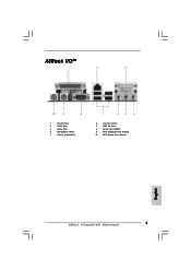
ASRock I/OTM 1 Parallel Port 2 RJ-45 Port 3 Game Port 4 Microphone (Pink) 5 Line In (Light Blue) 6 Line Out (Lime) 7 USB 2.0 Ports 8 Serial Port (COM1) 9 PS/2 Keyboard Port (Purple) 10 PS/2 Mouse Port (Green) English 3 ASRock K7Upgrade-600 Motherboard
ASRock I/OTM 1 Parallel Port 2 RJ-45 Port 3 Game Port 4 Microphone (Pink) 5 Line In (Light Blue) 6 Line Out (Lime) 7 USB 2.0 Ports 8 Serial Port (COM1) 9 PS/2 Keyboard Port (Purple) 10 PS/2 Mouse Port (Green) English 3 ASRock K7Upgrade-600 Motherboard
Quick Installation Guide
Page 4
... English In case any modifications of the motherboard can be subject to quality and endurance. ASRock website http://www.asrock.com 1.1 Package Contents ASRock K7Upgrade-600 Motherboard (ATX Form Factor: 12.0-in x 8.2-in, 30.5 cm x 20.8 cm) ASRock K7Upgrade-600 Quick Installation Guide ASRock K7Upgrade-600 Support CD One 80-conductor Ultra ATA 66/100/133 IDE Ribbon Cable One Ribbon...
... English In case any modifications of the motherboard can be subject to quality and endurance. ASRock website http://www.asrock.com 1.1 Package Contents ASRock K7Upgrade-600 Motherboard (ATX Form Factor: 12.0-in x 8.2-in, 30.5 cm x 20.8 cm) ASRock K7Upgrade-600 Quick Installation Guide ASRock K7Upgrade-600 Support CD One 80-conductor Ultra ATA 66/100/133 IDE Ribbon Cable One Ribbon...

Quick Installation Guide
Page 5
...: Speed: 802.3u (10/100 Ethernet), supports Wake-On-LAN Hardware Monitor: CPU Temperature Sensing Motherboard Temperature Sensing CPU Overheat Shutdown to Protect CPU Life (ASRock U-COP)(see CAUTION 1) CPU Fan Tachometer Chassis Fan Tachometer Voltage Monitoring: +12V, +5V, +3.3V, Vcore K8 Bridge: Supports CPU upgrade from AMD K7...USB 2.0: 8 USB 2.0 ports: include 4 ready-to-use USB 2.0 ports on the rear panel, plus two on-board header supporting 4 extra USB 2.0 ports (see CAUTION 3) ASRock I/O: 1 PS/2 mouse port, 1 PS/2 keyboard port, English 5 ASRock K7Upgrade-600 Motherboard
...: Speed: 802.3u (10/100 Ethernet), supports Wake-On-LAN Hardware Monitor: CPU Temperature Sensing Motherboard Temperature Sensing CPU Overheat Shutdown to Protect CPU Life (ASRock U-COP)(see CAUTION 1) CPU Fan Tachometer Chassis Fan Tachometer Voltage Monitoring: +12V, +5V, +3.3V, Vcore K8 Bridge: Supports CPU upgrade from AMD K7...USB 2.0: 8 USB 2.0 ports: include 4 ready-to-use USB 2.0 ports on the rear panel, plus two on-board header supporting 4 extra USB 2.0 ports (see CAUTION 3) ASRock I/O: 1 PS/2 mouse port, 1 PS/2 keyboard port, English 5 ASRock K7Upgrade-600 Motherboard

Quick Installation Guide
Page 6
... not work properly under Microsoft® Windows® XP SP1/2000 SP4. Frequencies other than the recommended CPU bus frequencies may cause permanent damage! 3. English 6 ASRock K7Upgrade-600 Motherboard To improve heat dissipation, remember to Microsoft® official document at http://www.microsoft.com/whdc/hwdev/bus/USB/USB2support.mspx 4.
... not work properly under Microsoft® Windows® XP SP1/2000 SP4. Frequencies other than the recommended CPU bus frequencies may cause permanent damage! 3. English 6 ASRock K7Upgrade-600 Motherboard To improve heat dissipation, remember to Microsoft® official document at http://www.microsoft.com/whdc/hwdev/bus/USB/USB2support.mspx 4.

Quick Installation Guide
Page 7
... cause severe damage to the chassis, please do not over-tighten the screws! Failure to static electricity, NEVER place your CPU fan and heatsink vendors. 7 ASRock K7Upgrade-600 Motherboard English STEP 3: Carefully insert the CPU into the socket until it on the socket while you install motherboard components or change any motherboard settings...
... cause severe damage to the chassis, please do not over-tighten the screws! Failure to static electricity, NEVER place your CPU fan and heatsink vendors. 7 ASRock K7Upgrade-600 Motherboard English STEP 3: Carefully insert the CPU into the socket until it on the socket while you install motherboard components or change any motherboard settings...
Quick Installation Guide
Page 8
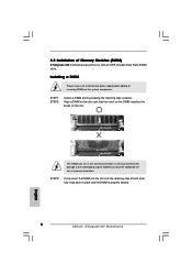
... provides two 184-pin DDR (Double Data Rate) DIMM slots. English The DIMM only fits in place and the DIMM is properly seated. 8 ASRock K7Upgrade-600 Motherboard It will cause permanent damage to disconnect power supply before adding or removing DIMMs or the system components. STEP 3: Firmly insert the DIMM into ...
... provides two 184-pin DDR (Double Data Rate) DIMM slots. English The DIMM only fits in place and the DIMM is properly seated. 8 ASRock K7Upgrade-600 Motherboard It will cause permanent damage to disconnect power supply before adding or removing DIMMs or the system components. STEP 3: Firmly insert the DIMM into ...

Quick Installation Guide
Page 9
...page 2, No. 12) J7 / J8 / J9 (page 2, No. 12) (5 x 2-pin; short ) (1 x 3-pin; short pin2, pin3) (4 x 3-pin; short pin2, pin3) 9 ASRock K7Upgrade-600 Motherboard English K8 Bridge (Orange-Colored Bridge (K8BRIDGE_1) + Brown-Colored Bridge (K8BRIDGE_2)): The set of K8 Bridge allows you upgrade the AMD 462-Pin CPU...an AMR slot! Please do NOT insert any AGP card into the orange-colored Bridge (K8BRIDGE_1) and AMR card into this K8 Bridge on K7Upgrade-600 motherboard. short ) (4 x 3-pin; CPU Type 462-Pin CPU (Default) Jumper Settings 2-Pin Jumpers 3-Pin Jumpers J14 J 6 (...
...page 2, No. 12) J7 / J8 / J9 (page 2, No. 12) (5 x 2-pin; short ) (1 x 3-pin; short pin2, pin3) (4 x 3-pin; short pin2, pin3) 9 ASRock K7Upgrade-600 Motherboard English K8 Bridge (Orange-Colored Bridge (K8BRIDGE_1) + Brown-Colored Bridge (K8BRIDGE_2)): The set of K8 Bridge allows you upgrade the AMD 462-Pin CPU...an AMR slot! Please do NOT insert any AGP card into the orange-colored Bridge (K8BRIDGE_1) and AMR card into this K8 Bridge on K7Upgrade-600 motherboard. short ) (4 x 3-pin; CPU Type 462-Pin CPU (Default) Jumper Settings 2-Pin Jumpers 3-Pin Jumpers J14 J 6 (...
Quick Installation Guide
Page 10
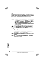
... cause permanent damage! Please do not install AGP cards into the slot 1.5V_AGP1 (see page 2, No. 33), or insert the AGP card with screws. 10 ASRock K7Upgrade-600 Motherboard English Installing an expansion card STEP 1: Before installing the expansion card, please make necessary hardware settings for the card before you removing the jumper...
... cause permanent damage! Please do not install AGP cards into the slot 1.5V_AGP1 (see page 2, No. 33), or insert the AGP card with screws. 10 ASRock K7Upgrade-600 Motherboard English Installing an expansion card STEP 1: Before installing the expansion card, please make necessary hardware settings for the card before you removing the jumper...

Quick Installation Guide
Page 11
... (see p.2, No. 27) Note: If the jumpers JL1 and JR1 are "Short" when jumper cap is placed on pins, the jumper is "Short". English 11 ASRock K7Upgrade-600 Motherboard Short Open Jumper Setting PS2_USB_PWR1 Short pin2, pin3 to enable (see p.2, No. 18) 2-pin jumper Note: CLRCMOS2 allows you to clear the CMOS when...
... (see p.2, No. 27) Note: If the jumpers JL1 and JR1 are "Short" when jumper cap is placed on pins, the jumper is "Short". English 11 ASRock K7Upgrade-600 Motherboard Short Open Jumper Setting PS2_USB_PWR1 Short pin2, pin3 to enable (see p.2, No. 18) 2-pin jumper Note: CLRCMOS2 allows you to clear the CMOS when...

Quick Installation Guide
Page 12
...-setting. For detailed information, please refer to your AMD CPU before you use the "Manual" option as the FSB setting in the Support CD. 12 ASRock K7Upgrade-600 Motherboard English To perform over clocking, you must set the CPU front side bus frequency. FSB_SEL0 FSB_SEL1 FSB_SEL2 (see p.2, No. 3) Note: The set of "CPU...
...-setting. For detailed information, please refer to your AMD CPU before you use the "Manual" option as the FSB setting in the Support CD. 12 ASRock K7Upgrade-600 Motherboard English To perform over clocking, you must set the CPU front side bus frequency. FSB_SEL0 FSB_SEL1 FSB_SEL2 (see p.2, No. 3) Note: The set of "CPU...

Quick Installation Guide
Page 13
... primary IDE connector (IDE1, blue) and CD-ROM to optimize compatibility and performance, please connect your IDE device vendor for internal storage devices. English 13 ASRock K7Upgrade-600 Motherboard FDD Connector (33-pin FLOPPY1) (see p.2, No. 16) SATA2 SATA1 These two Serial ATA (SATA) connectors support SATA data cables for the details. Please...
... primary IDE connector (IDE1, blue) and CD-ROM to optimize compatibility and performance, please connect your IDE device vendor for internal storage devices. English 13 ASRock K7Upgrade-600 Motherboard FDD Connector (33-pin FLOPPY1) (see p.2, No. 16) SATA2 SATA1 These two Serial ATA (SATA) connectors support SATA data cables for the details. Please...

Quick Installation Guide
Page 14
... devices. USB 2.0 Header (9-pin USB45) (see p.2, No. 25) This header supports an optional wireless transmitting and receiving infrared module. English 14 ASRock K7Upgrade-600 Motherboard Then connect the white end of SATA power cable to -use USB 2.0 ports on the rear panel. USB 2.0 Header (9-pin USB67) (see...AUX1) (CD1: see p.2, No. 34) (AUX1: see p.2, No. 35) AUX1 CD1 Front Panel Audio Header (9-pin AUDIO1) (see p.2, No. 22) ASRock I /O provides you to -use USB 2.0 ports on the drive. This is available to the power connector on the rear panel. Serial ATA (SATA) Power ...
... devices. USB 2.0 Header (9-pin USB45) (see p.2, No. 25) This header supports an optional wireless transmitting and receiving infrared module. English 14 ASRock K7Upgrade-600 Motherboard Then connect the white end of SATA power cable to -use USB 2.0 ports on the rear panel. USB 2.0 Header (9-pin USB67) (see...AUX1) (CD1: see p.2, No. 34) (AUX1: see p.2, No. 35) AUX1 CD1 Front Panel Audio Header (9-pin AUDIO1) (see p.2, No. 22) ASRock I /O provides you to -use USB 2.0 ports on the drive. This is available to the power connector on the rear panel. Serial ATA (SATA) Power ...

Quick Installation Guide
Page 15
... Fan Connector (3-pin CPU_FAN1) (see p.2, No. 2) ATX Power Connector (20-pin ATXPWR1) (see p.2, No. 36) This header accommodates several system front panel functions. English 15 ASRock K7Upgrade-600 Motherboard Please connect the chassis speaker to this header.
... Fan Connector (3-pin CPU_FAN1) (see p.2, No. 2) ATX Power Connector (20-pin ATXPWR1) (see p.2, No. 36) This header accommodates several system front panel functions. English 15 ASRock K7Upgrade-600 Motherboard Please connect the chassis speaker to this header.

Quick Installation Guide
Page 16
.... STEP 4: Connect the other end of the SATA data cable to the SATA hard disk. 2.7 Hot Plug and Hot Swap Functions for SATA HDDs K7Upgrade-600 motherboard supports Hot Plug and Hot Swap functions for the action to insert and remove the SATA HDDs while the system is called "Hot Swap...power-on and in working condition. If the SATA HDDs are built as RAID1 then it is still power-on and in working condition. 16 ASRock K7Upgrade-600 Motherboard English If SATA HDDs are NOT set for RAID configuration, it cannot perform Hot Plug if the OS has been installed into the drive...
.... STEP 4: Connect the other end of the SATA data cable to the SATA hard disk. 2.7 Hot Plug and Hot Swap Functions for SATA HDDs K7Upgrade-600 motherboard supports Hot Plug and Hot Swap functions for the action to insert and remove the SATA HDDs while the system is called "Hot Swap...power-on and in working condition. If the SATA HDDs are built as RAID1 then it is still power-on and in working condition. 16 ASRock K7Upgrade-600 Motherboard English If SATA HDDs are NOT set for RAID configuration, it cannot perform Hot Plug if the OS has been installed into the drive...

Quick Installation Guide
Page 17
... on your SATA HDDs, you may start to SATA Hard Disks Installation and RAID Configuration", which is located in Windows environment. STEP 1: Insert the ASRock Support CD into the floppy drive. Please insert a floppy diskette into the floppy drive at this moment!) STEP 2: During POST at the following path...need to set the RAID configuration by using "VIA RAID Tool" in the folder at the following path: .. \ VIA RAID Tool 17 ASRock K7Upgrade-600 Motherboard English Once you have the SATA driver diskette ready, you start to boot your system, or you will lose ALL data in the ...
... on your SATA HDDs, you may start to SATA Hard Disks Installation and RAID Configuration", which is located in Windows environment. STEP 1: Insert the ASRock Support CD into the floppy drive. Please insert a floppy diskette into the floppy drive at this moment!) STEP 2: During POST at the following path...need to set the RAID configuration by using "VIA RAID Tool" in the folder at the following path: .. \ VIA RAID Tool 17 ASRock K7Upgrade-600 Motherboard English Once you have the SATA driver diskette ready, you start to boot your system, or you will lose ALL data in the ...

Quick Installation Guide
Page 18
... double-click on the motherboard stores BIOS Setup Utility. When you how to scroll through the following path: ..\ MPEGAV \ AVSEQ01.DAT 18 ASRock K7Upgrade-600 Motherboard English "PC-DIY Live Demo" ASRock presents you a multimedia PC-DIY live demo, which allows you to install your CD-ROM drive. Software Support CD information This motherboard...
... double-click on the motherboard stores BIOS Setup Utility. When you how to scroll through the following path: ..\ MPEGAV \ AVSEQ01.DAT 18 ASRock K7Upgrade-600 Motherboard English "PC-DIY Live Demo" ASRock presents you a multimedia PC-DIY live demo, which allows you to install your CD-ROM drive. Software Support CD information This motherboard...

Quick Installation Guide
Page 19
19 ASRock K7Upgrade-600 Motherboard
19 ASRock K7Upgrade-600 Motherboard


