
User Manual
Page 3
...Setup Menu 28 3. Boot Setup Menu 30 5. Exit Menu 31 3 Contents 1 Introduction 4 1.1 Package Contents 4 1.2 Specifications 5 1.3 Motherboard Layout 7 1.4 ASRock I/O PlusTM 8 2 Installation 9 2.1 Screw Holes 9 2.2 Pre-installation Precautions 9 2.3 CPU Installation 10 2.4 Installation of CPU Fan and Heatsink 10 2.5 Installation ... Modules (DIMM 11 2.6 Expansion Slots (PCI and AGP Slots 12 2.7 Jumpers Setup 13 2.8 Connectors 15 2.9 Serial ATA (SATA) Hard Disks Installation / RAID Configurations 18 3 BIOS Setup 19 3.1 BIOS Setup Utility 19 3.1.1 BIOS Menu Bar 19 3.1.2 ...
...Setup Menu 28 3. Boot Setup Menu 30 5. Exit Menu 31 3 Contents 1 Introduction 4 1.1 Package Contents 4 1.2 Specifications 5 1.3 Motherboard Layout 7 1.4 ASRock I/O PlusTM 8 2 Installation 9 2.1 Screw Holes 9 2.2 Pre-installation Precautions 9 2.3 CPU Installation 10 2.4 Installation of CPU Fan and Heatsink 10 2.5 Installation ... Modules (DIMM 11 2.6 Expansion Slots (PCI and AGP Slots 12 2.7 Jumpers Setup 13 2.8 Connectors 15 2.9 Serial ATA (SATA) Hard Disks Installation / RAID Configurations 18 3 BIOS Setup 19 3.1 BIOS Setup Utility 19 3.1.1 BIOS Menu Bar 19 3.1.2 ...

User Manual
Page 4
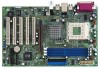
...SATA) HDD Power Cable (Optional) One ASRock I/O PlusTM Shield One Game Port Bracket (Optional) 4 Chapter 1 and 2 of this manual contain introduction of advanced BIOS setup is offered on page 24 for advanced users' reference. More information of the motherboard and step-bystep installation guide. ASRock website http://www.asrock.com 1.1 Package Contents ASRock K7S8XE...+ Motherboard (ATX Form Factor: 12.0-in x 7.5-in, 30.5 cm x 19.1 cm) ASRock K7S8XE+ Quick Installation Guide ASRock K7S8XE+ Support CD...
...SATA) HDD Power Cable (Optional) One ASRock I/O PlusTM Shield One Game Port Bracket (Optional) 4 Chapter 1 and 2 of this manual contain introduction of advanced BIOS setup is offered on page 24 for advanced users' reference. More information of the motherboard and step-bystep installation guide. ASRock website http://www.asrock.com 1.1 Package Contents ASRock K7S8XE...+ Motherboard (ATX Form Factor: 12.0-in x 7.5-in, 30.5 cm x 19.1 cm) ASRock K7S8XE+ Quick Installation Guide ASRock K7S8XE+ Support CD...
User Manual
Page 5
...1 DDR DIMM slot, Max. 1GB IDE: IDE1: ATA 133 / Ultra DMA Mode 6; Supports up to 4 IDE devices Serial ATA: 2 SATA connectors, support up to 2 SATA devices at1.5Gb/s data transfer rate Floppy Port: Supports up to support 2 additional USB 2.0 ports (see CAUTION 3) USB 2.0: 8 USB 2.0 ...; 1 serial port: COM1; 1 parallel port: ECP/EPP support; 1 RJ 45 port; 6 default USB 2.0 ports; CPU overheat shutdown to protect CPU life (ASRock U-COP)(see CAUTION 1); IDE2: ATA 133 / Ultra DMA Mode 6; 1.2 Specifications Platform: ATX Form Factor (12.0-in x 7.5-in, 30.5-cm x 19.1-cm)...
...1 DDR DIMM slot, Max. 1GB IDE: IDE1: ATA 133 / Ultra DMA Mode 6; Supports up to 4 IDE devices Serial ATA: 2 SATA connectors, support up to 2 SATA devices at1.5Gb/s data transfer rate Floppy Port: Supports up to support 2 additional USB 2.0 ports (see CAUTION 3) USB 2.0: 8 USB 2.0 ...; 1 serial port: COM1; 1 parallel port: ECP/EPP support; 1 RJ 45 port; 6 default USB 2.0 ports; CPU overheat shutdown to protect CPU life (ASRock U-COP)(see CAUTION 1); IDE2: ATA 133 / Ultra DMA Mode 6; 1.2 Specifications Platform: ATX Form Factor (12.0-in x 7.5-in, 30.5-cm x 19.1-cm)...

User Manual
Page 7
... FID0 FID1 FID2 FID3 FID4 FSB_SEL0 FSB_SEL1 SiS 748 29 9 28 1 AUDIO1 JL1 10 JR1 27 26 AGP1 11 Audio CODEC 25 LAN PHY PCI 1 K7S8XE+ PCI 2 SiS 964 12 24 Super I/O PCI 3 PCI 4 13 CHA_FAN1 14 CMOS Battery 15 SATA1 SATA2 23 2MB BIOS ATA133 AGP 8X... SATA DDR400 FLOPPY1 16 17 PCI 5 CLRCMOS2 5.1 CH PANEL 1 PLED PWRBTN 1 GAME1 USB 2.0 1 USB67 1 IR1 1 SPEAKER1 1 HDLED RESET 22 21 20 19 18 1 PS2_USB_PWR1 Jumper 2 CPU ...
... FID0 FID1 FID2 FID3 FID4 FSB_SEL0 FSB_SEL1 SiS 748 29 9 28 1 AUDIO1 JL1 10 JR1 27 26 AGP1 11 Audio CODEC 25 LAN PHY PCI 1 K7S8XE+ PCI 2 SiS 964 12 24 Super I/O PCI 3 PCI 4 13 CHA_FAN1 14 CMOS Battery 15 SATA1 SATA2 23 2MB BIOS ATA133 AGP 8X... SATA DDR400 FLOPPY1 16 17 PCI 5 CLRCMOS2 5.1 CH PANEL 1 PLED PWRBTN 1 GAME1 USB 2.0 1 USB67 1 IR1 1 SPEAKER1 1 HDLED RESET 22 21 20 19 18 1 PS2_USB_PWR1 Jumper 2 CPU ...

User Manual
Page 15
...(39-pin IDE2, see p.7 item 7) PIN1 IDE1 PIN1 IDE2 connect the blue end connect the black end to the motherboard to the SATA hard disk or the SATA connector on this motherboard, please set the IDE device as "Master". FDD Connector (33-pin FLOPPY1) (see p.7 item 15) SATA1 ...SATA2 These two Serial ATA (SATA) connectors support SATA data cables for the details. Serial ATA Connectors (SATA1: see p.7 item 14) (SATA2: see p.7 item 16) Pin1 FLOPPY1 the red-striped...
...(39-pin IDE2, see p.7 item 7) PIN1 IDE1 PIN1 IDE2 connect the blue end connect the black end to the motherboard to the SATA hard disk or the SATA connector on this motherboard, please set the IDE device as "Master". FDD Connector (33-pin FLOPPY1) (see p.7 item 15) SATA1 ...SATA2 These two Serial ATA (SATA) connectors support SATA data cables for the details. Serial ATA Connectors (SATA1: see p.7 item 14) (SATA2: see p.7 item 16) Pin1 FLOPPY1 the red-striped...

User Manual
Page 16
...DUMMY This USB45 connector is shared with the USB 2.0 ports 4,5 on ASRock I /O PlusTM. Infrared Module Connector (5-pin IR1) (see p.7 item 29) GND +5VA BACKOUT-R BACKOUT-L 1 A U D - O U T- Serial ATA (SATA) Power Cable (Optional) connect to the SATA HDD power connector Please connect the black end of the power supply.... DUMMY 1 GND P+6 P-6 USB_PWR ASRock I/O PlusTM provides you GND GND CD1 to the power connector on the rear panel. Then connect the white end of SATA connect to the power cable to the power powersupply connector of SATA power cable to receive stereo audio input...
...DUMMY This USB45 connector is shared with the USB 2.0 ports 4,5 on ASRock I /O PlusTM. Infrared Module Connector (5-pin IR1) (see p.7 item 29) GND +5VA BACKOUT-R BACKOUT-L 1 A U D - O U T- Serial ATA (SATA) Power Cable (Optional) connect to the SATA HDD power connector Please connect the black end of the power supply.... DUMMY 1 GND P+6 P-6 USB_PWR ASRock I/O PlusTM provides you GND GND CD1 to the power connector on the rear panel. Then connect the white end of SATA connect to the power cable to the power powersupply connector of SATA power cable to receive stereo audio input...

User Manual
Page 18
Please find the document, "Guide to check the installation guide in the Support CD: .. \ RAID_SETUP_GUIDE \ English.PDF 18 2.9 Serial ATA (SATA) Hard Disks Installation / RAID Configuration This motherboard adopts SiS 964 southbridge chipset that supports Serial ATA (SATA) hard disks and RAID functions. Before you install the SATA hard disks and configure the RAID function, you need to SATA Hard Disks Installation and RAID Configuration", at the following path in the Support CD for proper installation and configuration.
Please find the document, "Guide to check the installation guide in the Support CD: .. \ RAID_SETUP_GUIDE \ English.PDF 18 2.9 Serial ATA (SATA) Hard Disks Installation / RAID Configuration This motherboard adopts SiS 964 southbridge chipset that supports Serial ATA (SATA) hard disks and RAID functions. Before you install the SATA hard disks and configure the RAID function, you need to SATA Hard Disks Installation and RAID Configuration", at the following path in the Support CD for proper installation and configuration.

User Manual
Page 26
... Port Parallel Port Mode EPP Version Parallel Port IRQ Parallel Port DMA Channel OnBoard Midi Port Midi IRQ Select OnBoard Game Port OnBoard IDE OnBoard SATA OnBoard LAN OnBoard AC' 97 Audio Auto Auto Disabled Auto ECP+EPP 1.9 Auto Auto Disabled 5 200 Both Enabled Enabled Auto to select PCI clocks. F1...
... Port Parallel Port Mode EPP Version Parallel Port IRQ Parallel Port DMA Channel OnBoard Midi Port Midi IRQ Select OnBoard Game Port OnBoard IDE OnBoard SATA OnBoard LAN OnBoard AC' 97 Audio Auto Auto Disabled Auto ECP+EPP 1.9 Auto Auto Disabled 5 200 Both Enabled Enabled Auto to select PCI clocks. F1...

User Manual
Page 27
...options: [Disabled], [330], [300], [290], [292]. Midi IRQ Select: Use this to monitor the parameters for Game Port or disable Game Port. OnBoard SATA: This allows you to select Midi IRQ. Configuration options: [Auto], [Disabled], [3F8 / IRQ4 / COM1], [2F8 / IRQ3 / COM2], [3E8 / IRQ4... options: [Auto], [Disabled], [378], [278]. Configuration options: [Disabled], [200], [208]. Or you to enable or disable the onboard SATA controller. System Hardware Monitor: You can check the status of the parallel port. OnBoard Midi Port: Select address for the onboard AC'97 Audio ...
...options: [Disabled], [330], [300], [290], [292]. Midi IRQ Select: Use this to monitor the parameters for Game Port or disable Game Port. OnBoard SATA: This allows you to select Midi IRQ. Configuration options: [Auto], [Disabled], [3F8 / IRQ4 / COM1], [2F8 / IRQ3 / COM2], [3E8 / IRQ4... options: [Auto], [Disabled], [378], [278]. Configuration options: [Disabled], [200], [208]. Or you to enable or disable the onboard SATA controller. System Hardware Monitor: You can check the status of the parallel port. OnBoard Midi Port: Select address for the onboard AC'97 Audio ...
