
User Manual
Page 3
...Power Setup Menu 29 4. Exit Menu 31 3 Boot Setup Menu 30 5. Security Setup Menu 28 3. Contents 1 Introduction 4 1.1 Package Contents 4 1.2 Specifications 5 1.3 Motherboard Layout 7 1.4 ASRock I/O PlusTM 8 2 Installation 9 2.1 Screw Holes 9 2.2 Pre-installation Precautions 9 2.3 CPU Installation 10 2.4 Installation of CPU Fan and Heatsink 10 2.5 Installation of Memory...System 23 4.2 Support CD Information 23 4.2.1 Running Support CD 23 4.2.2 Drivers Menu 23 4.2.3 Utilities Menu 23 4.2.4 ASRock "PC-DIY Live Demo" Program 23 4.2.5 Contact Information 23 Appendix 24 1.
...Power Setup Menu 29 4. Exit Menu 31 3 Boot Setup Menu 30 5. Security Setup Menu 28 3. Contents 1 Introduction 4 1.1 Package Contents 4 1.2 Specifications 5 1.3 Motherboard Layout 7 1.4 ASRock I/O PlusTM 8 2 Installation 9 2.1 Screw Holes 9 2.2 Pre-installation Precautions 9 2.3 CPU Installation 10 2.4 Installation of CPU Fan and Heatsink 10 2.5 Installation of Memory...System 23 4.2 Support CD Information 23 4.2.1 Running Support CD 23 4.2.2 Drivers Menu 23 4.2.3 Utilities Menu 23 4.2.4 ASRock "PC-DIY Live Demo" Program 23 4.2.5 Contact Information 23 Appendix 24 1.

User Manual
Page 4
... on page 24 for advanced users' reference. In case any modifications of the motherboard and step-bystep installation guide. ASRock website http://www.asrock.com 1.1 Package Contents ASRock K7S8XE+ Motherboard (ATX Form Factor: 12.0-in x 7.5-in, 30.5 cm x 19.1 cm) ASRock K7S8XE+ Quick Installation Guide ASRock K7S8XE+ Support CD One 80-conductor Ultra ATA 66/100/133 IDE Ribbon Cable...
... on page 24 for advanced users' reference. In case any modifications of the motherboard and step-bystep installation guide. ASRock website http://www.asrock.com 1.1 Package Contents ASRock K7S8XE+ Motherboard (ATX Form Factor: 12.0-in x 7.5-in, 30.5 cm x 19.1 cm) ASRock K7S8XE+ Quick Installation Guide ASRock K7S8XE+ Support CD One 80-conductor Ultra ATA 66/100/133 IDE Ribbon Cable...
User Manual
Page 6
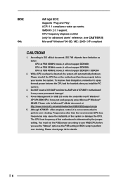
...to perform over clocking. Frequencies other than the recommended CPU bus frequencies may cause the instability of this motherboard is determined by the jumpersetting. It may not work properly under Microsoft® Windows® XP ...! 1. CPU at FSB 200MHz mode, it will not support DDR400; Please check if the CPU fan on the motherboard functions properly before you use the "Manual" option as below: CPU at FSB 333MHz mode, it will not support...insert a 3.3V AGP card into the AGP slot of K7S8XE+ motherboard! ACPI 1.1 compliance wake up events; Supports "Plug and Play";
...to perform over clocking. Frequencies other than the recommended CPU bus frequencies may cause the instability of this motherboard is determined by the jumpersetting. It may not work properly under Microsoft® Windows® XP ...! 1. CPU at FSB 200MHz mode, it will not support DDR400; Please check if the CPU fan on the motherboard functions properly before you use the "Manual" option as below: CPU at FSB 333MHz mode, it will not support...insert a 3.3V AGP card into the AGP slot of K7S8XE+ motherboard! ACPI 1.1 compliance wake up events; Supports "Plug and Play";

User Manual
Page 7
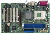
1.3 Motherboard Layout 1 2 PS/2 Mouse PS/2 Keyboard 1 PS2_USB_PWR1 3 4 19.1cm (7.5 in) 5 6 30.5cm (12 in) ATXPWR1 PARALLEL PORT COM1 DDR1 (64/72 bit, 184-pin module) DDR2 (... FID0 FID1 FID2 FID3 FID4 FSB_SEL0 FSB_SEL1 SiS 748 29 9 28 1 AUDIO1 JL1 10 JR1 27 26 AGP1 11 Audio CODEC 25 LAN PHY PCI 1 K7S8XE+ PCI 2 SiS 964 12 24 Super I/O PCI 3 PCI 4 13 CHA_FAN1 14 CMOS Battery 15 SATA1 SATA2 23 2MB BIOS ATA133 AGP 8X SATA DDR400 FLOPPY1...
1.3 Motherboard Layout 1 2 PS/2 Mouse PS/2 Keyboard 1 PS2_USB_PWR1 3 4 19.1cm (7.5 in) 5 6 30.5cm (12 in) ATXPWR1 PARALLEL PORT COM1 DDR1 (64/72 bit, 184-pin module) DDR2 (... FID0 FID1 FID2 FID3 FID4 FSB_SEL0 FSB_SEL1 SiS 748 29 9 28 1 AUDIO1 JL1 10 JR1 27 26 AGP1 11 Audio CODEC 25 LAN PHY PCI 1 K7S8XE+ PCI 2 SiS 964 12 24 Super I/O PCI 3 PCI 4 13 CHA_FAN1 14 CMOS Battery 15 SATA1 SATA2 23 2MB BIOS ATA133 AGP 8X SATA DDR400 FLOPPY1...

User Manual
Page 9
...2. Before you and damages to motherboard components. 2.1 Screw Holes Place screws into the holes indicated by the edges and do so may cause severe damage to ensure that the motherboard fits into it on the carpet or the like. Chapter 2 Installation K7S8XE+ is detached from the wall ...socket before touching any motherboard settings. 1. Before you handle components. 3. Failure to do not touch the ...
...2. Before you and damages to motherboard components. 2.1 Screw Holes Place screws into the holes indicated by the edges and do so may cause severe damage to ensure that the motherboard fits into it on the carpet or the like. Chapter 2 Installation K7S8XE+ is detached from the wall ...socket before touching any motherboard settings. 1. Before you handle components. 3. Failure to do not touch the ...

User Manual
Page 11
... the slot. Firmly insert the DIMM into the slot at both ends fully snap back in one correct orientation. Step 3. Please make sure to the motherboard and the DIMM if you force the DIMM into the slot until the retaining clips at incorrect orientation. It will cause permanent damage to disconnect... clips outward. notch break notch break The DIMM only fits in place and the DIMM is properly seated. 11 Step 2. 2.5 Installation of Memory Modules (DIMM) K7S8XE+ motherboard provides three 184-pin DDR (Double Data Rate) DIMM slots.
... the slot. Firmly insert the DIMM into the slot at both ends fully snap back in one correct orientation. Step 3. Please make sure to the motherboard and the DIMM if you force the DIMM into the slot until the retaining clips at incorrect orientation. It will cause permanent damage to disconnect... clips outward. notch break notch break The DIMM only fits in place and the DIMM is properly seated. 11 Step 2. 2.5 Installation of Memory Modules (DIMM) K7S8XE+ motherboard provides three 184-pin DDR (Double Data Rate) DIMM slots.

User Manual
Page 12
... 2. Step 5. Step 6. PCI slots: PCI slots are 5 PCI slots and 1 AGP slot on the slot. For the voltage information of your motherboard is unplugged. Please read the documentation of K7S8XE+ motherboard! Remove the system unit cover (if your VGA card, please check with the slot and press firmly until the card is used... 4. Installing an expansion card Step 1. Remove the bracket facing the slot that you start the installation. AGP slot: The AGP slot is completely seated on K7S8XE+ motherboard. Fasten the card to use .
... 2. Step 5. Step 6. PCI slots: PCI slots are 5 PCI slots and 1 AGP slot on the slot. For the voltage information of your motherboard is unplugged. Please read the documentation of K7S8XE+ motherboard! Remove the system unit cover (if your VGA card, please check with the slot and press firmly until the card is used... 4. Installing an expansion card Step 1. Remove the bracket facing the slot that you start the installation. AGP slot: The AGP slot is completely seated on K7S8XE+ motherboard. Fasten the card to use .

User Manual
Page 13
... 266MHz 1_2 FSB_SEL0 1_2 FSB_SEL1 1_2 FSB_SEL0 2_3 FSB_SEL1 FSB 333MHz FSB 400MHz Note: The setting of the CPU front side bus frequency of this motherboard is placed on CLRCMOS2 for PS/2 or +5V +5VSB USB wake up the system first, and then shut it requires 2 Amp and higher standby current...
... 266MHz 1_2 FSB_SEL0 1_2 FSB_SEL1 1_2 FSB_SEL0 2_3 FSB_SEL1 FSB 333MHz FSB 400MHz Note: The setting of the CPU front side bus frequency of this motherboard is placed on CLRCMOS2 for PS/2 or +5V +5VSB USB wake up the system first, and then shut it requires 2 Amp and higher standby current...

User Manual
Page 15
...-pin IDE1, see p.7 item 8) (39-pin IDE2, see p.7 item 7) PIN1 IDE1 PIN1 IDE2 connect the blue end connect the black end to the motherboard to optimize compatibility and performance, please connect your IDE device vendor for internal storage devices. Besides, to the IDE devices 80-conductor ATA 66/100.../133 cable Note: If you use only one IDE device on the motherboard. 15 Serial ATA (SATA) Data Cable Either end of the motherboard! FDD Connector (33-pin FLOPPY1) (see p.7 item 15) SATA1 SATA2 These two Serial ATA (SATA) connectors ...
...-pin IDE1, see p.7 item 8) (39-pin IDE2, see p.7 item 7) PIN1 IDE1 PIN1 IDE2 connect the blue end connect the black end to the motherboard to optimize compatibility and performance, please connect your IDE device vendor for internal storage devices. Besides, to the IDE devices 80-conductor ATA 66/100.../133 cable Note: If you use only one IDE device on the motherboard. 15 Serial ATA (SATA) Data Cable Either end of the motherboard! FDD Connector (33-pin FLOPPY1) (see p.7 item 15) SATA1 SATA2 These two Serial ATA (SATA) connectors ...

User Manual
Page 18
2.9 Serial ATA (SATA) Hard Disks Installation / RAID Configuration This motherboard adopts SiS 964 southbridge chipset that supports Serial ATA (SATA) hard disks and RAID functions. Before you install the SATA hard disks and configure the RAID function, you need to SATA Hard Disks Installation and RAID Configuration", at the following path in the Support CD for proper installation and configuration. Please find the document, "Guide to check the installation guide in the Support CD: .. \ RAID_SETUP_GUIDE \ English.PDF 18
2.9 Serial ATA (SATA) Hard Disks Installation / RAID Configuration This motherboard adopts SiS 964 southbridge chipset that supports Serial ATA (SATA) hard disks and RAID functions. Before you install the SATA hard disks and configure the RAID function, you need to SATA Hard Disks Installation and RAID Configuration", at the following path in the Support CD for proper installation and configuration. Please find the document, "Guide to check the installation guide in the Support CD: .. \ RAID_SETUP_GUIDE \ English.PDF 18

User Manual
Page 19
... you wish to enter the BIOS Setup after POST, restart the system by pressing + + , or by turning the system off and then back on the motherboard stores the BIOS Setup Utility. Please press during the Power-On-Self-Test (POST) to enter the BIOS Setup Utility, otherwise, POST continues with their...
... you wish to enter the BIOS Setup after POST, restart the system by pressing + + , or by turning the system off and then back on the motherboard stores the BIOS Setup Utility. Please press during the Power-On-Self-Test (POST) to enter the BIOS Setup Utility, otherwise, POST continues with their...

User Manual
Page 23
... if the system detects installed devices. Refer to your OS documentation for more about ASRock, welcome to know more information. 4.2 Support CD Information The Support CD that came with the motherboard contains necessary drivers and useful utilities that the motherboard supports. or you may contact your CD-ROM drive. Chapter 4 Software Support 4.1 Install...
... if the system detects installed devices. Refer to your OS documentation for more about ASRock, welcome to know more information. 4.2 Support CD Information The Support CD that came with the motherboard contains necessary drivers and useful utilities that the motherboard supports. or you may contact your CD-ROM drive. Chapter 4 Software Support 4.1 Install...
User Manual
Page 24
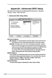
...:Select Sub-Menu F9:Setup Defaults F10:Save & Exit CPU Host Frequency: [By Jumper]: It is recommended to [Auto], the motherboard detects the memory module(s) inserted and automatically assigns appropriate frequency. This is determined by the jumper-setting. [Manual]: This allows user... "Security," "Power," "Boot," and "Exit." 1. Appendix: Advanced BIOS Setup This section will let the CPU host frequency of this motherboard is not recommended unless you thoroughly know the feature. Spread Spectrum: This field should always be [Disabled] for better system stability. 24 ...
...:Select Sub-Menu F9:Setup Defaults F10:Save & Exit CPU Host Frequency: [By Jumper]: It is recommended to [Auto], the motherboard detects the memory module(s) inserted and automatically assigns appropriate frequency. This is determined by the jumper-setting. [Manual]: This allows user... "Security," "Power," "Boot," and "Exit." 1. Appendix: Advanced BIOS Setup This section will let the CPU host frequency of this motherboard is not recommended unless you thoroughly know the feature. Spread Spectrum: This field should always be [Disabled] for better system stability. 24 ...

User Manual
Page 27
... to select Midi IRQ. If this option is [ECP+CPP]. Configuration options: [Disabled], [330], [300], [290], [292]. OnBoard Game Port: Select address for CPU temperature, Motherboard temperature, CPU fan speed, and critical voltage. OnBoard SATA: This allows you to enable or disable the onboard LAN feature. OnBoard LAN: This allows you...
... to select Midi IRQ. If this option is [ECP+CPP]. Configuration options: [Disabled], [330], [300], [290], [292]. OnBoard Game Port: Select address for CPU temperature, Motherboard temperature, CPU fan speed, and critical voltage. OnBoard SATA: This allows you to enable or disable the onboard LAN feature. OnBoard LAN: This allows you...

User Manual
Page 3
Boot Menu 26 5. Advanced Menu 20 2. Power Menu 25 4. Exit Menu 27 3 Contents 1 Introduction 4 1.1 Package Contents 4 1.2 Specifications 5 1.3 Motherboard Layout 7 1.4 ASRock I/OTM 8 2 Installation 9 2.1 Screw Holes 9 2.2 Pre-installation Precautions 9 2.3 CPU Installation 9 2.4 Installation of Heatsink and CPU fan 10 2.5 Installation... Operating System 19 4.2 Support CD Information 19 4.2.1 Running Support CD 19 4.2.2 Drivers Menu 19 4.2.3 Utilities Menu 19 4.2.4 ASRock "PC-DIY Live Demo" Program 19 4.2.5 Contact Information 19 Appendix 20 1. Security Menu 24 3.
Boot Menu 26 5. Advanced Menu 20 2. Power Menu 25 4. Exit Menu 27 3 Contents 1 Introduction 4 1.1 Package Contents 4 1.2 Specifications 5 1.3 Motherboard Layout 7 1.4 ASRock I/OTM 8 2 Installation 9 2.1 Screw Holes 9 2.2 Pre-installation Precautions 9 2.3 CPU Installation 9 2.4 Installation of Heatsink and CPU fan 10 2.5 Installation... Operating System 19 4.2 Support CD Information 19 4.2.1 Running Support CD 19 4.2.2 Drivers Menu 19 4.2.3 Utilities Menu 19 4.2.4 ASRock "PC-DIY Live Demo" Program 19 4.2.5 Contact Information 19 Appendix 20 1. Security Menu 24 3.
User Manual
Page 4
... manual occur, the updated version will be available on page 20 offers more advanced BIOS setup information. ASRock website http://www.asrock.com 1.1 Package Contents ASRock K7S8XE motherboard (ATX form factor: 12.0" x 9.6", 30.5 x 24.4 cm) ASRock K7S8XE Quick Installation Guide ASRock AMD-SiS Series Support CD 1 cable for IDE devices (1 x ATA 66/100/133) 1 cable for new DIY...
... manual occur, the updated version will be available on page 20 offers more advanced BIOS setup information. ASRock website http://www.asrock.com 1.1 Package Contents ASRock K7S8XE motherboard (ATX form factor: 12.0" x 9.6", 30.5 x 24.4 cm) ASRock K7S8XE Quick Installation Guide ASRock AMD-SiS Series Support CD 1 cable for IDE devices (1 x ATA 66/100/133) 1 cable for new DIY...

User Manual
Page 6
... Microsoft® official document at FSB 200MHz mode, it will also be overclocked proportionally. Do NOT use a 3.3V AGP card on the motherboard functions properly before you install the PC system. 3. It may cause permanent damage! 4. When the CPU frequency of the system or damage the... CPU. 6 Please check if the CPU fan on K7S8XE's AGP slot! Please refer to perform over clocking. Power Management for USB 2.0 works fine under Microsoft® Windows® 98/ME/2000. CAUTION...
... Microsoft® official document at FSB 200MHz mode, it will also be overclocked proportionally. Do NOT use a 3.3V AGP card on the motherboard functions properly before you install the PC system. 3. It may cause permanent damage! 4. When the CPU frequency of the system or damage the... CPU. 6 Please check if the CPU fan on K7S8XE's AGP slot! Please refer to perform over clocking. Power Management for USB 2.0 works fine under Microsoft® Windows® 98/ME/2000. CAUTION...

User Manual
Page 7
1.3 Motherboard Layout 22 1 23 4 5 24.4cm (9.6 in) PS/2 1 Mouse PS2_USB_PWR1 PS/2 Keyboard CPU_FAN1 COM1 PARALLEL PORT DDR DIMM1 (64/72 bit, 184-pin module) DDR DIMM2 (... Audio CODEC 18 Super I/O SiS 748 Chipset FSB_SEL0 1 FSB_SEL1 1 25 26 01 23 45 AGP1 PCI 1 PCI 2 SiS 963L 6 CHA_FAN1 9 8 IDE2 16 7 IDE1 PCI 3 PCI 4 K7S8XE CLRCMOS1 CMOS Battery CLRCMOS2 27 10 FLOPPY1 PCI 5 ` 2MB 11 BIOS PCI 6 ATA133 USB2.0 5.1CH USB45 1 IR1 1 SPEAKER1 1 PANEL 1 PLED PWRBTN 1 HDLED RESET 15 12...
1.3 Motherboard Layout 22 1 23 4 5 24.4cm (9.6 in) PS/2 1 Mouse PS2_USB_PWR1 PS/2 Keyboard CPU_FAN1 COM1 PARALLEL PORT DDR DIMM1 (64/72 bit, 184-pin module) DDR DIMM2 (... Audio CODEC 18 Super I/O SiS 748 Chipset FSB_SEL0 1 FSB_SEL1 1 25 26 01 23 45 AGP1 PCI 1 PCI 2 SiS 963L 6 CHA_FAN1 9 8 IDE2 16 7 IDE1 PCI 3 PCI 4 K7S8XE CLRCMOS1 CMOS Battery CLRCMOS2 27 10 FLOPPY1 PCI 5 ` 2MB 11 BIOS PCI 6 ATA133 USB2.0 5.1CH USB45 1 IR1 1 SPEAKER1 1 PANEL 1 PLED PWRBTN 1 HDLED RESET 15 12...

User Manual
Page 9
... power cord is an ATX form factor (12.0" x 9.6", 30.5 x 24.4 cm) motherboard. Unlock the socket by circles to secure the motherboard to unplug the power cord before you handle components. 3. Chapter 2 Installation K7S8XE is detached from the wall socket before you install motherboard components or change any component, place it on the carpet or...
... power cord is an ATX form factor (12.0" x 9.6", 30.5 x 24.4 cm) motherboard. Unlock the socket by circles to secure the motherboard to unplug the power cord before you handle components. 3. Chapter 2 Installation K7S8XE is detached from the wall socket before you install motherboard components or change any component, place it on the carpet or...

User Manual
Page 10
... 1. Unlock a DIMM slot by pressing the retaining clips outward. The lever clicks on the slot. Please make sure to avoid bending of Memory Modules (DIMM) K7S8XE motherboard provides three 184-pin DDR (Double Data Rate) DIMM slots. Align a DIMM on the slot such that the notch on the DIMM matches the break...
... 1. Unlock a DIMM slot by pressing the retaining clips outward. The lever clicks on the slot. Please make sure to avoid bending of Memory Modules (DIMM) K7S8XE motherboard provides three 184-pin DDR (Double Data Rate) DIMM slots. Align a DIMM on the slot such that the notch on the DIMM matches the break...

