
User Manual
Page 5
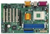
... +3V, Vcore; ACPI 1.1 compliance wake up to protect CPU life (ASRock U-COP)(see CAUTION 1); PC3200 (DDR400) for advanced users' reference, see CAUTION 4) PS/2: 1 keyboard... 1 RJ 45 port; 4 rear default USB 2.0 ports; 1 serial port: COM 1; 1 parallel port: ECP/EPP support; Can connect up events; PC2700 (DDR333) for two ASRock I/OTM: additional USB 2.0 ports upgrade (see CAUTION 5) OS: ...Socket A (462 pins) for 3 DDR DIMM slots, Max. 3GB; South Bridge: SiS 963L, supports USB 2.0, ATA 133 Memory: 3 DDR DIMM slots: DDR1, DDR2, and DDR3 PC1600 (DDR200) / PC2100 (DDR266)...
... +3V, Vcore; ACPI 1.1 compliance wake up to protect CPU life (ASRock U-COP)(see CAUTION 1); PC3200 (DDR400) for advanced users' reference, see CAUTION 4) PS/2: 1 keyboard... 1 RJ 45 port; 4 rear default USB 2.0 ports; 1 serial port: COM 1; 1 parallel port: ECP/EPP support; Can connect up events; PC2700 (DDR333) for two ASRock I/OTM: additional USB 2.0 ports upgrade (see CAUTION 5) OS: ...Socket A (462 pins) for 3 DDR DIMM slots, Max. 3GB; South Bridge: SiS 963L, supports USB 2.0, ATA 133 Memory: 3 DDR DIMM slots: DDR1, DDR2, and DDR3 PC1600 (DDR200) / PC2100 (DDR266)...
User Manual
Page 6
... It may cause permanent damage! 4. Please refer to perform over clocking, other than the recommended CPU bus frequencies may cause the instability of K7S8X or K7S8XE motherboard! Frequencies other clocks, such as below: SiS 746FX: CPU at FSB 333MHz mode, it will not support DDR400; CPU ... the motherboard functions properly before you install the PC system. 3. SiS 748: CPU at http://www.microsoft.com/whdc/hwdev/bus/USB/USB2support.mspx 5. Although K7S8X / K7S8XE offers stepless control, it is set to SiS official document, SiS 746FX and SiS 748 chipsets have limitation as PCI ...
... It may cause permanent damage! 4. Please refer to perform over clocking, other than the recommended CPU bus frequencies may cause the instability of K7S8X or K7S8XE motherboard! Frequencies other clocks, such as below: SiS 746FX: CPU at FSB 333MHz mode, it will not support DDR400; CPU ... the motherboard functions properly before you install the PC system. 3. SiS 748: CPU at http://www.microsoft.com/whdc/hwdev/bus/USB/USB2support.mspx 5. Although K7S8X / K7S8XE offers stepless control, it is set to SiS official document, SiS 746FX and SiS 748 chipsets have limitation as PCI ...
User Manual
Page 7
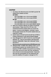
...DDR3 (64/72 bit, 184-pin module) ATXPWR1 30.5cm (12.0 in) PARALLEL PORT 29 28 27 26 25 24 23 22 21 20 LAN USB 2.0 Ports USB 2.0 Ports GGAAMMEE AAUUDDIIOO11 Line out LiLInnineein MMIniicc in CPU_FAN1 1 FID0 1 FID1 1 FID2 1 FID3 1 FID4 1 FSB_SEL0 1 FSB_SEL1 AUDIO1 1 JR1 JL1 ...AUDIO CODEC SiS 746FX Chipset 01 23 45 IDE2 IDE1 AGP 8X AGP1 PCI 1 LAN PCI 2 PHY Super I/O PCI 3 2MB BIOS 5.1CH K7S8X PCI 4 ATA133 PCI 5 USB 2.0 REV. 3.01 USB45 1 SiS 963L CHA_FAN1 CMOS Battery FLOPPY1 CLRCMOS2 IR1 SPEAKER1 1 1 PANEL 1 PLED PWRBTN 1 HDLED RST 7 8 9 10 11...
...DDR3 (64/72 bit, 184-pin module) ATXPWR1 30.5cm (12.0 in) PARALLEL PORT 29 28 27 26 25 24 23 22 21 20 LAN USB 2.0 Ports USB 2.0 Ports GGAAMMEE AAUUDDIIOO11 Line out LiLInnineein MMIniicc in CPU_FAN1 1 FID0 1 FID1 1 FID2 1 FID3 1 FID4 1 FSB_SEL0 1 FSB_SEL1 AUDIO1 1 JR1 JL1 ...AUDIO CODEC SiS 746FX Chipset 01 23 45 IDE2 IDE1 AGP 8X AGP1 PCI 1 LAN PCI 2 PHY Super I/O PCI 3 2MB BIOS 5.1CH K7S8X PCI 4 ATA133 PCI 5 USB 2.0 REV. 3.01 USB45 1 SiS 963L CHA_FAN1 CMOS Battery FLOPPY1 CLRCMOS2 IR1 SPEAKER1 1 1 PANEL 1 PLED PWRBTN 1 HDLED RST 7 8 9 10 11...

User Manual
Page 8
... (64/72 bit, 184-pin module) ATXPWR1 30.5cm (12.0 in) PARALLEL PORT 29 28 27 26 25 24 23 22 21 20 LAN USB 2.0 Ports USB 2.0 Ports GGAAMMEE AAUUDDIIOO11 Line out LiLInnineein MMIniicc in CPU_FAN1 1 FID0 1 FID1 1 FID2 1 FID3 1 FID4 1 FSB_SEL0 1 FSB_SEL1 AUDIO1 1 JR1 ...jumpers (FSB_SEL0) 11 AGP slot (AGP1) 13 Chassis fan connector (CHA_FAN1) 15 Clear CMOS (CLRCMOS2, 2-pin jumper) 17 External speaker connector (SPEAKER 1) 19 USB 2.0 header (USB45, Blue) 21 PCI slots (PCI 1- 5) 23 AUDIO CODEC 25 JR1 jumper 27 Internal audio connector: AUX1 (White) 29 FID Jumpers (...
... (64/72 bit, 184-pin module) ATXPWR1 30.5cm (12.0 in) PARALLEL PORT 29 28 27 26 25 24 23 22 21 20 LAN USB 2.0 Ports USB 2.0 Ports GGAAMMEE AAUUDDIIOO11 Line out LiLInnineein MMIniicc in CPU_FAN1 1 FID0 1 FID1 1 FID2 1 FID3 1 FID4 1 FSB_SEL0 1 FSB_SEL1 AUDIO1 1 JR1 ...jumpers (FSB_SEL0) 11 AGP slot (AGP1) 13 Chassis fan connector (CHA_FAN1) 15 Clear CMOS (CLRCMOS2, 2-pin jumper) 17 External speaker connector (SPEAKER 1) 19 USB 2.0 header (USB45, Blue) 21 PCI slots (PCI 1- 5) 23 AUDIO CODEC 25 JR1 jumper 27 Internal audio connector: AUX1 (White) 29 FID Jumpers (...

User Manual
Page 9
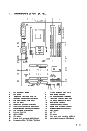
1.5 ASRock I/OTM (K7S8X / K7S8XE) 1 2 3 10 9 8 7 654 1 Parallel port 3 Game port 5 Line In (Light Blue) 7 USB 2.0 ports 9 PS/2 keyboard port (Purple) 2 RJ-45 port 4 Microphone (Pink) 6 Line Out (Lime) 8 Serial port (COM1) 10 PS/2 mouse port (Green) 9
1.5 ASRock I/OTM (K7S8X / K7S8XE) 1 2 3 10 9 8 7 654 1 Parallel port 3 Game port 5 Line In (Light Blue) 7 USB 2.0 ports 9 PS/2 keyboard port (Purple) 2 RJ-45 port 4 Microphone (Pink) 6 Line Out (Lime) 8 Serial port (COM1) 10 PS/2 mouse port (Green) 9

User Manual
Page 13
... "OPEN". Please follow the figures above to support the function. 13 JR1(see p.7/p.8 item 25) JL1(see p.7/p.8 item 1) +5V +5VSB +5VSB (standby) for PS/2 or USB wake up events. The illustration shows a 3-pin jumper whose pin1 and pin2 are short (see fig. 1), both jumper caps on JL1 and JR1 are setup...
... "OPEN". Please follow the figures above to support the function. 13 JR1(see p.7/p.8 item 25) JL1(see p.7/p.8 item 1) +5V +5VSB +5VSB (standby) for PS/2 or USB wake up events. The illustration shows a 3-pin jumper whose pin1 and pin2 are short (see fig. 1), both jumper caps on JL1 and JR1 are setup...

User Manual
Page 16
.... Connect an ATX power supply to an external speaker. This connector accommodates several system front panel functions. If those 4 USB 2.0 ports on the rear panel. USB 2.0 header (9-pin USB45) (see p.7/p.8 item 19) Infrared module connector (5-pin IR1) (see p.7/p.8 item 18) Internal... 1 SPEAKER DUMMY DUMMY +5V GND +12V CHA_FAN_SPEED CPU_FAN_SPEED +12V GND ASRock I/OTM provides 4 default USB 2.0 ports on the rear panel are not sufficient, this USB 2.0 header is an interface for 2 additional USB 2.0 ports. This is available for front panel audio cable that allows ...
.... Connect an ATX power supply to an external speaker. This connector accommodates several system front panel functions. If those 4 USB 2.0 ports on the rear panel. USB 2.0 header (9-pin USB45) (see p.7/p.8 item 19) Infrared module connector (5-pin IR1) (see p.7/p.8 item 18) Internal... 1 SPEAKER DUMMY DUMMY +5V GND +12V CHA_FAN_SPEED CPU_FAN_SPEED +12V GND ASRock I/OTM provides 4 default USB 2.0 ports on the rear panel are not sufficient, this USB 2.0 header is an interface for 2 additional USB 2.0 ports. This is available for front panel audio cable that allows ...

User Manual
Page 23
... unless the installed AGP card's specifications requires other sizes. Over Vcore Voltage: Enable this to enable "Over Vcore Voltage" feature. USB Controller: Use this item will increase the CPU Vcore voltage around 5%. etc. The default value is not recommended to enable or ...disable the use of mapped memory for graphics memory. VERSION 3.31a Chipset Configuration [ Setup Help ] AGP Aperture Size USB Controller USB Device Legacy Support DRAM CAS Latency Over Vcore Voltage 32M Disabled Disabled Auto Disabled to emulate legacy I/O devices such as mouse, keyboard...
... unless the installed AGP card's specifications requires other sizes. Over Vcore Voltage: Enable this to enable "Over Vcore Voltage" feature. USB Controller: Use this item will increase the CPU Vcore voltage around 5%. etc. The default value is not recommended to enable or ...disable the use of mapped memory for graphics memory. VERSION 3.31a Chipset Configuration [ Setup Help ] AGP Aperture Size USB Controller USB Device Legacy Support DRAM CAS Latency Over Vcore Voltage 32M Disabled Disabled Auto Disabled to emulate legacy I/O devices such as mouse, keyboard...


