User Manual
Page 4
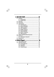
3 . Software Support 63 4.1 Install Operating System 63 4.2 Support CD Information 63 4.2.1 Running Support CD 63 4.2.2 Drivers Menu 63 4.2.3 Utilities Menu 63 4.2.4 Contact Information 63 4 BIOS SETUP UTILITY 4 0 3.1 Introduction 40 3.1.1 BIOS Menu Bar 40 3.1.2 Navigation Keys 41 3.2 Main Screen 41 3.3 Smart Screen 42 3.4 Advanced Screen 43 3.4.1 CPU Configuration 44 3.4.2 Memory Configuration 47 3.4.3 Chipset Configuration...
3 . Software Support 63 4.1 Install Operating System 63 4.2 Support CD Information 63 4.2.1 Running Support CD 63 4.2.2 Drivers Menu 63 4.2.3 Utilities Menu 63 4.2.4 Contact Information 63 4 BIOS SETUP UTILITY 4 0 3.1 Introduction 40 3.1.1 BIOS Menu Bar 40 3.1.2 Navigation Keys 41 3.2 Main Screen 41 3.3 Smart Screen 42 3.4 Advanced Screen 43 3.4.1 CPU Configuration 44 3.4.2 Memory Configuration 47 3.4.3 Chipset Configuration...

User Manual
Page 5
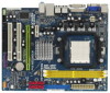
... cards and CPU support lists on ASRock website without notice. Because the motherboard specifications and the BIOS software might be updated, the content of this manual will be subject to BIOS setup and information of the Support ... for purchasing ASRock K10N78M Pro motherboard, a reliable motherboard produced under ASRock's consistently stringent quality control. 1. www.asrock.com/support/index.asp 1.1 Package Contents ASRock K10N78M Pro Motherboard (Micro ATX Form Factor: 9.6-in x 7.5-in, 24.4 cm x 19.1 cm) ASRock K10N78M Pro Quick Installation Guide ASRock K10N78M Pro Support CD ...
... cards and CPU support lists on ASRock website without notice. Because the motherboard specifications and the BIOS software might be updated, the content of this manual will be subject to BIOS setup and information of the Support ... for purchasing ASRock K10N78M Pro motherboard, a reliable motherboard produced under ASRock's consistently stringent quality control. 1. www.asrock.com/support/index.asp 1.1 Package Contents ASRock K10N78M Pro Motherboard (Micro ATX Form Factor: 9.6-in x 7.5-in, 24.4 cm x 19.1 cm) ASRock K10N78M Pro Quick Installation Guide ASRock K10N78M Pro Support CD ...

User Manual
Page 7
... Flash (see CAUTION 11) - Intelligent Energy Saver (see CAUTION 12) - Instant Boot - CPU Quiet Fan 7 ASRock OC Tuner (see CAUTION 7) - 6 x Ready-to 12.5% (see CAUTION 9) - 8Mb AMI BIOS - HD Audio Jack: Line in header - Supports Smart BIOS - Drivers, Utilities, AntiVirus Software (Trial Version) - CPU Temperature Sensing - Supports jumperfree - Boot Failure Guard (B.F.G.) - Chassis Temperature...
... Flash (see CAUTION 11) - Intelligent Energy Saver (see CAUTION 12) - Instant Boot - CPU Quiet Fan 7 ASRock OC Tuner (see CAUTION 7) - 6 x Ready-to 12.5% (see CAUTION 9) - 8Mb AMI BIOS - HD Audio Jack: Line in header - Supports Smart BIOS - Drivers, Utilities, AntiVirus Software (Trial Version) - CPU Temperature Sensing - Supports jumperfree - Boot Failure Guard (B.F.G.) - Chassis Temperature...

User Manual
Page 8
...port to the adapter vendor for the minimum hardware requirement and the passed 1080p Blu-ray (BD) / HD-DVD films in the BIOS, applying Untied Overclocking Technology, or using the thirdparty overclocking tools. You can support DVI/HDCP and HDMI format signal. You may be ... (BD) / HD-DVD playback support on the AM2+ CPU you implement Dual Channel Memory Technology, make sure to SATAII connector directly. 8 ASRock website http://www.asrock.com 4. The maximum shared memory size is defined by overclocking. FCC, CE, WHQL * For detailed product information, please visit our website: ...
...port to the adapter vendor for the minimum hardware requirement and the passed 1080p Blu-ray (BD) / HD-DVD films in the BIOS, applying Untied Overclocking Technology, or using the thirdparty overclocking tools. You can support DVI/HDCP and HDMI format signal. You may be ... (BD) / HD-DVD playback support on the AM2+ CPU you implement Dual Channel Memory Technology, make sure to SATAII connector directly. 8 ASRock website http://www.asrock.com 4. The maximum shared memory size is defined by overclocking. FCC, CE, WHQL * For detailed product information, please visit our website: ...

User Manual
Page 9
... system, please check if the CPU fan on the AM2 CPU you enable this tool and save the new BIOS file to access ASRock Instant Flash. 9. ASRock website: http://www.asrock.com 12. While CPU overheat is a revolutionary technology that the USB flash drive or hard drive must use ...Intelligent Energy Saver function, please enable Cool 'n' Quiet option in the BIOS setup in Flash ROM. Power Management for the operation procedures of ASRock OC Tuner. Featuring an advanced proprietary hardware and software design, Intelligent Energy Saver is detected, the system ...
... system, please check if the CPU fan on the AM2 CPU you enable this tool and save the new BIOS file to access ASRock Instant Flash. 9. ASRock website: http://www.asrock.com 12. While CPU overheat is a revolutionary technology that the USB flash drive or hard drive must use ...Intelligent Energy Saver function, please enable Cool 'n' Quiet option in the BIOS setup in Flash ROM. Power Management for the operation procedures of ASRock OC Tuner. Featuring an advanced proprietary hardware and software design, Intelligent Energy Saver is detected, the system ...

User Manual
Page 12
... 11 SATAII Connector (SATAII_1 (PORT 0), Red) (HD_AUDIO1, Lime) 12 SATAII Connector (SATAII_3 (PORT 2), Red) 26 PCI Slots (PCI1- 2) 13 SPI BIOS Chip 27 PCI Express x16 Slot (PCIE2, Green) 14 Clear CMOS Jumper (CLRCMOS1) 28 PCI Express x1 Slot (PCIE1, White) 15 Chassis Fan Connector (...(PORT 1) 28 27 26 PCIE1 Hybrid SLI Gigabit LAN Super I/O AUDIO CODEC HD_AUDIO1 1 CD1 COM1 1 FLOPPY1 K10N78M Pro PCIE2 PCI1 RAID PCI2 LPT1 1 CMOS BATTERY 1 CLRCMOS1 IR1 1 USB8_9 1 USB6_7 1 RoHS 8Mb BIOS CHA_FAN1 SPEAKER1 1 PLED PWRBTN PANEL 1 1 HDLED RESET 10 11 12 13 14 15 16 17 25 24 ...
... 11 SATAII Connector (SATAII_1 (PORT 0), Red) (HD_AUDIO1, Lime) 12 SATAII Connector (SATAII_3 (PORT 2), Red) 26 PCI Slots (PCI1- 2) 13 SPI BIOS Chip 27 PCI Express x16 Slot (PCIE2, Green) 14 Clear CMOS Jumper (CLRCMOS1) 28 PCI Express x1 Slot (PCIE1, White) 15 Chassis Fan Connector (...(PORT 1) 28 27 26 PCIE1 Hybrid SLI Gigabit LAN Super I/O AUDIO CODEC HD_AUDIO1 1 CD1 COM1 1 FLOPPY1 K10N78M Pro PCIE2 PCI1 RAID PCI2 LPT1 1 CMOS BATTERY 1 CLRCMOS1 IR1 1 USB8_9 1 USB6_7 1 RoHS 8Mb BIOS CHA_FAN1 SPEAKER1 1 PLED PWRBTN PANEL 1 1 HDLED RESET 10 11 12 13 14 15 16 17 25 24 ...
User Manual
Page 19
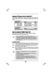
Boot your BIOS change and exit BIOS setup. If you plan to use onboard VGA output, after step 1 to 3, please follow below installation and setup procedures according to the mode you want ... can choose GeForce® Boost mode (Boost Performance) only. Install one compatible PCI Express graphics card to enter BIOS setup. Press to PCIE2 slot (green). After reboot your request. 19 A. Set up the BIOS option "Primary Graphics Display" to [Onboard], and save your system. C. For users using single monitor: If you connect...
Boot your BIOS change and exit BIOS setup. If you plan to use onboard VGA output, after step 1 to 3, please follow below installation and setup procedures according to the mode you want ... can choose GeForce® Boost mode (Boost Performance) only. Install one compatible PCI Express graphics card to enter BIOS setup. Press to PCIE2 slot (green). After reboot your request. 19 A. Set up the BIOS option "Primary Graphics Display" to [Onboard], and save your system. C. For users using single monitor: If you connect...

User Manual
Page 20
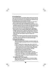
...and exit BIOS setup. Then you will find the Hybrid icon on your system. B. Save your computer. Power off your Windows® taskbar. Connect the monitor cable to your system. Hybrid SLITM driver is in the following path of ASRock support CD: (There are two ASRock support CD... 5. Step 6. Hybrid SLITM driver is GeForce® Boost mode (Boost Performance). The default setting is in the following path of ASRock support CD: (There are two ASRock support CD in the motherboard gift box pack, please choose the one for Windows® VistaTM / VistaTM 64-bit.) ..\Drivers\Hybrid...
...and exit BIOS setup. Then you will find the Hybrid icon on your system. B. Save your computer. Power off your Windows® taskbar. Connect the monitor cable to your system. Hybrid SLITM driver is in the following path of ASRock support CD: (There are two ASRock support CD... 5. Step 6. Hybrid SLITM driver is GeForce® Boost mode (Boost Performance). The default setting is in the following path of ASRock support CD: (There are two ASRock support CD in the motherboard gift box pack, please choose the one for Windows® VistaTM / VistaTM 64-bit.) ..\Drivers\Hybrid...

User Manual
Page 21
Boot into OS. dows® taskbar. C. For the proper installation procedures, please refer to enter BIOS setup. Boot your system. Step 5. Dual Monitors Step 1. Step 2. Step 3. Install Hybrid SLITM driver from our support CD to your system. Restart your system ...the correspondent connector on PCIE2 slot. Step 4. Then you will find the Hybrid icon on your system is in the following path of ASRock support CD: (There are two ASRock support CD in the motherboard gift box pack, please choose the one for Windows® VistaTM / VistaTM 64-bit.) ..\Drivers\Hybrid SLI...
Boot into OS. dows® taskbar. C. For the proper installation procedures, please refer to enter BIOS setup. Boot your system. Step 5. Dual Monitors Step 1. Step 2. Step 3. Install Hybrid SLITM driver from our support CD to your system. Restart your system ...the correspondent connector on PCIE2 slot. Step 4. Then you will find the Hybrid icon on your system is in the following path of ASRock support CD: (There are two ASRock support CD in the motherboard gift box pack, please choose the one for Windows® VistaTM / VistaTM 64-bit.) ..\Drivers\Hybrid SLI...
User Manual
Page 23
... Properties dialog that the value you select is no need to the VGA/D-Sub port on PCI Express VGA card, you do not adjust the BIOS setup, the default value of "Share Memory", [Auto], will be designated as appropriate for the diaplay icon identified by the number 2. C. E. Set... set up a multi-monitor display. Press to the steps below . When you can easily enjoy the benefits of the multi-monitor according to enter BIOS setup. Click "Extend my Windows desktop onto this motherboard. For Windows® VistaTM / VistaTM 64-bit OS: Right click the desktop, choose "Personalize...
... Properties dialog that the value you select is no need to the VGA/D-Sub port on PCI Express VGA card, you do not adjust the BIOS setup, the default value of "Share Memory", [Auto], will be designated as appropriate for the diaplay icon identified by the number 2. C. E. Set... set up a multi-monitor display. Press to the steps below . When you can easily enjoy the benefits of the multi-monitor according to enter BIOS setup. Click "Extend my Windows desktop onto this motherboard. For Windows® VistaTM / VistaTM 64-bit OS: Right click the desktop, choose "Personalize...

User Manual
Page 25
... B. Install "Onboard HDMI HD Audio Driver" from ASRock Support CD to your system manually. A. Step 2: Enter Windows® to your system. Click "Hardware and Sound", and click "Sound". Change the default setting "Speaker" to [Auto]. Enter BIOS SETUP UTILITY Advanced screen Chipset Configuration. Step 2: Install ...HDMI audio function is installed, the OS default will not function. For Windows® XP / XP 64-bit OS Step 1: Set up BIOS. Therefore, the onboard audio jack will output the audio signal through HDMI audio. Set the option "OnBoard HDMI HD Audio" to "Digital...
... B. Install "Onboard HDMI HD Audio Driver" from ASRock Support CD to your system manually. A. Step 2: Enter Windows® to your system. Click "Hardware and Sound", and click "Sound". Change the default setting "Speaker" to [Auto]. Enter BIOS SETUP UTILITY Advanced screen Chipset Configuration. Step 2: Install ...HDMI audio function is installed, the OS default will not function. For Windows® XP / XP 64-bit OS Step 1: Set up BIOS. Therefore, the onboard audio jack will output the audio signal through HDMI audio. Set the option "OnBoard HDMI HD Audio" to "Digital...

User Manual
Page 26
... pin2 are setup. The data in CMOS. After waiting for 15 seconds, use a jumper cap to clear the CMOS when you just finish updating the BIOS, you do not clear the CMOS right after you need to short pin2 and pin3 on pins, the jumper is "Short". Jumper Setting PS2_USB_PW1 1_2.../2 or USB wake up the system first, and then shut it requires 2 Amp and higher standby current provided by power supply. If you update the BIOS.
... pin2 are setup. The data in CMOS. After waiting for 15 seconds, use a jumper cap to clear the CMOS when you just finish updating the BIOS, you do not clear the CMOS right after you need to short pin2 and pin3 on pins, the jumper is "Short". Jumper Setting PS2_USB_PW1 1_2.../2 or USB wake up the system first, and then shut it requires 2 Amp and higher standby current provided by power supply. If you update the BIOS.

User Manual
Page 29
... / VistaTM 64-bit OS: Go to the "Front Mic" Tab in "Front Mic" of "Playback" portion. Click "Set Default Device" to the ground pin. Enter BIOS Setup Utility. Please connect the chassis speaker to this connector and match the black wire to make the Front Mic as default record device. Set...
... / VistaTM 64-bit OS: Go to the "Front Mic" Tab in "Front Mic" of "Playback" portion. Click "Set Default Device" to the ground pin. Enter BIOS Setup Utility. Please connect the chassis speaker to this connector and match the black wire to make the Front Mic as default record device. Set...
User Manual
Page 35
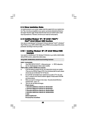
Using SATA / SATAII HDDs with NCQ and Hot Plug functions STEP 1: Set Up BIOS. Please select CD-ROM as the boot device. D. Enter BIOS SETUP UTILITY Advanced screen IDE Configuration. STEP 2: Make a SATA / SATAII driver diskette. A. Generate AHCI Driver diskette for WindowsXP 3. ...install. 2.15.1 Installing Windows® XP / XP 64-bit Without RAID Functions If you see these messages, Please choose: 1. Insert the ASRock Support CD into your optical drive to install Windows® XP / Windows® XP 64-bit on your optical drive first. Then, ...
Using SATA / SATAII HDDs with NCQ and Hot Plug functions STEP 1: Set Up BIOS. Please select CD-ROM as the boot device. D. Enter BIOS SETUP UTILITY Advanced screen IDE Configuration. STEP 2: Make a SATA / SATAII driver diskette. A. Generate AHCI Driver diskette for WindowsXP 3. ...install. 2.15.1 Installing Windows® XP / XP 64-bit Without RAID Functions If you see these messages, Please choose: 1. Insert the ASRock Support CD into your optical drive to install Windows® XP / Windows® XP 64-bit on your optical drive first. Then, ...
User Manual
Page 36
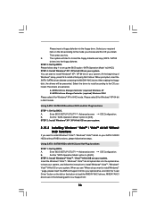
... want to install Windows® VistaTM / Windows® VistaTM 64-bit OS on your system. Enter BIOS SETUP UTILITY Advanced screen IDE Configuration. " page, please insert the ASRock Support CD into the floppy drive. E. Please follow the instruction to install Windows® VistaTM / Windows...® VistaTM 64-bit on your SATA / SATAII HDDs without NCQ and Hot Plug functions STEP 1: Set Up BIOS. NVIDIA nForce Storage Controller (required...
... want to install Windows® VistaTM / Windows® VistaTM 64-bit OS on your system. Enter BIOS SETUP UTILITY Advanced screen IDE Configuration. " page, please insert the ASRock Support CD into the floppy drive. E. Please follow the instruction to install Windows® VistaTM / Windows...® VistaTM 64-bit on your SATA / SATAII HDDs without NCQ and Hot Plug functions STEP 1: Set Up BIOS. NVIDIA nForce Storage Controller (required...

User Manual
Page 37
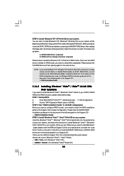
... HDDs with RAID functions, please follow step 1 to the BIOS RAID installation guide part of the document in the following section...continue the installation. Enter BIOS SETUP UTILITY Advanced screen IDE Configuration. STEP 3: Set Up BIOS. Enter BIOS SETUP UTILITY Advanced screen ...STEP 1: Set Up BIOS. Please follow below steps...diskette. STEP 4: Use "RAID Installation Guide" to set up the BIOS option "SATA Operation Mode" to install Windows® XP, Windows®...NCQ and Hot Plug functions STEP 1: Set Up BIOS. A. Before you start to configure RAID function, you want to ...
... HDDs with RAID functions, please follow step 1 to the BIOS RAID installation guide part of the document in the following section...continue the installation. Enter BIOS SETUP UTILITY Advanced screen IDE Configuration. STEP 3: Set Up BIOS. Enter BIOS SETUP UTILITY Advanced screen ...STEP 1: Set Up BIOS. Please follow below steps...diskette. STEP 4: Use "RAID Installation Guide" to set up the BIOS option "SATA Operation Mode" to install Windows® XP, Windows®...NCQ and Hot Plug functions STEP 1: Set Up BIOS. A. Before you start to configure RAID function, you want to ...
User Manual
Page 38
...\ I386 \ Vista (For Windows® VistaTM OS) .. \ AMD64 \ Vista64 (For Windows® VistaTM 64-bit OS) 38 The drivers are two ASRock Support CD in BIOS first. NVIDIA nForce Storage Controller (required) Please select A and B for Windows® XP / XP 64-bit in RAID mode. (There are two RAID... still need to [RAID] in the motherboard gift box pack, please choose the one .) NOTE. Enter BIOS SETUP UTILITY Advanced screen IDE Configuration. B. " page, please insert the ASRock Support CD into the optical drive to load the NVIDIA® RAID drivers. You can start to configure RAID...
...\ I386 \ Vista (For Windows® VistaTM OS) .. \ AMD64 \ Vista64 (For Windows® VistaTM 64-bit OS) 38 The drivers are two ASRock Support CD in BIOS first. NVIDIA nForce Storage Controller (required) Please select A and B for Windows® XP / XP 64-bit in RAID mode. (There are two RAID... still need to [RAID] in the motherboard gift box pack, please choose the one .) NOTE. Enter BIOS SETUP UTILITY Advanced screen IDE Configuration. B. " page, please insert the ASRock Support CD into the optical drive to load the NVIDIA® RAID drivers. You can start to configure RAID...

User Manual
Page 39
... Overclocking Technology This motherboard supports Untied Overclocking Technology, which means during overclocking, but PCI / PCIE buses are in BIOS first. NOTE. Before you enable Untied Overclocking function, please enter "Overclock Mode" option of BIOS setup to set up "SATA Operation Mode" to [CPU, PCIE, Async.]. Therefore, CPU FSB is untied during overclocking...
... Overclocking Technology This motherboard supports Untied Overclocking Technology, which means during overclocking, but PCI / PCIE buses are in BIOS first. NOTE. Before you enable Untied Overclocking function, please enter "Overclock Mode" option of BIOS setup to set up "SATA Operation Mode" to [CPU, PCIE, Async.]. Therefore, CPU FSB is untied during overclocking...

User Manual
Page 40
..., and they may also restart by pressing the reset button on the system chassis. You may not exactly match what you wish to enter the BIOS SETUP UTILITY after POST, restart the system by pressing + + , or by turning the system off and then back on the menu bar, and then...press or during the Power-On-Self-Test (POST) to configure your system. The SPI Memory on your requirements Advanced To set up the advanced BIOS features H/W Monitor To display current hardware status Boot To set up the computer. erating System Security To set up the default system device to your...
..., and they may also restart by pressing the reset button on the system chassis. You may not exactly match what you wish to enter the BIOS SETUP UTILITY after POST, restart the system by pressing + + , or by turning the system off and then back on the menu bar, and then...press or during the Power-On-Self-Test (POST) to configure your system. The SPI Memory on your requirements Advanced To set up the advanced BIOS features H/W Monitor To display current hardware status Boot To set up the computer. erating System Security To set up the default system device to your...

User Manual
Page 41
... Use this item to specify the system time. 3.1.2Navigation Keys Please check the following table for all the settings To save changes and exit the BIOS SETUP UTILITY To jump to the Exit Screen or exit the current screen 3.2 Main Screen When you enter the... UTILITY Main Smart Advanced H/W Monitor Boot Security Exit System Overview System Time System Date [14:00:09] [Mon 07/06/2009] BIOS Version Processor Type : K10N78M Pro P1.00 : AMD Athlon (tm) 64 Processor 3800+ (64bit) Processor Speed : 2400MHz Microcode Update : 70FF1/0 L1 Cache Size : 128KB L2 Cache Size : 512KB Total Memory...
... Use this item to specify the system time. 3.1.2Navigation Keys Please check the following table for all the settings To save changes and exit the BIOS SETUP UTILITY To jump to the Exit Screen or exit the current screen 3.2 Main Screen When you enter the... UTILITY Main Smart Advanced H/W Monitor Boot Security Exit System Overview System Time System Date [14:00:09] [Mon 07/06/2009] BIOS Version Processor Type : K10N78M Pro P1.00 : AMD Athlon (tm) 64 Processor 3800+ (64bit) Processor Speed : 2400MHz Microcode Update : 70FF1/0 L1 Cache Size : 128KB L2 Cache Size : 512KB Total Memory...


