

User Manual
Page 4
...Contents 1 1.2 Specifications 2 1.3 Motherboard Layout 5 1.4 I/O Panel 7 Chapter 2 Installation 9 2.1 Installing Memory Modules (SO-DIMM) 10 2.2 Expansion Slots (PCI Express Slots) 12 2.3 Jumpers Setup 13 2.4 Onboard Headers and Connectors 14 Chapter 3 Software and Utilities Operation 18 3.1 Installing Drivers 18 3.2 ASRock Live Update & APP Shop 19 3.2.1 UI Overview 19 3.2.2 Apps 20 3.2.3 BIOS & Drivers 23 3.2.4 Setting 24 3.3 Enabling USB Ports for Windows® 7 Installation 25 Chapter 4 UEFI SETUP UTILITY 28 4.1 Introduction 28 4.1.1 UEFI Menu Bar 28...
...Contents 1 1.2 Specifications 2 1.3 Motherboard Layout 5 1.4 I/O Panel 7 Chapter 2 Installation 9 2.1 Installing Memory Modules (SO-DIMM) 10 2.2 Expansion Slots (PCI Express Slots) 12 2.3 Jumpers Setup 13 2.4 Onboard Headers and Connectors 14 Chapter 3 Software and Utilities Operation 18 3.1 Installing Drivers 18 3.2 ASRock Live Update & APP Shop 19 3.2.1 UI Overview 19 3.2.2 Apps 20 3.2.3 BIOS & Drivers 23 3.2.4 Setting 24 3.3 Enabling USB Ports for Windows® 7 Installation 25 Chapter 4 UEFI SETUP UTILITY 28 4.1 Introduction 28 4.1.1 UEFI Menu Bar 28...

User Manual
Page 6
...for specific information about the model you for purchasing ASRock J3160DC-ITX motherboard, a reliable motherboard produced under ASRock's consistently stringent quality control. Chapter 3 contains the operation guide of the BIOS setup. You may find the latest VGA cards and CPU support list on ASRock's website without notice. ASRock website http://www.asrock.com. 1.1 Package Contents • ASRock J3160DC-ITX Motherboard (Mini-ITX Form Factor) • ASRock J3160DC-ITX Quick Installation Guide • ASRock J3160DC-ITX Support CD • 2 x Serial ATA (SATA) Data Cables (Optional...
...for specific information about the model you for purchasing ASRock J3160DC-ITX motherboard, a reliable motherboard produced under ASRock's consistently stringent quality control. Chapter 3 contains the operation guide of the BIOS setup. You may find the latest VGA cards and CPU support list on ASRock's website without notice. ASRock website http://www.asrock.com. 1.1 Package Contents • ASRock J3160DC-ITX Motherboard (Mini-ITX Form Factor) • ASRock J3160DC-ITX Quick Installation Guide • ASRock J3160DC-ITX Support CD • 2 x Serial ATA (SATA) Data Cables (Optional...
User Manual
Page 7
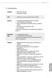
... GHz) Memory • Dual Channel DDR3/DDR3L Memory Technology • 2 x DDR3/DDR3L SO-DIMM Slots • Supports DDR3/DDR3L 1600/1066 non-ECC, un-buffered memory • Max. Graphics • Integrated Intel® HD Graphics 400: 12 EUs inside (Up to 4K x 2K (3840x2160) @ 30Hz or 2560x1600 @ 60Hz • Supports Auto Lip Sync, xvYCC and HBR (High Bit Rate Audio) with HDMI Port (Compliant HDMI monitor is installed, please install it into...
... GHz) Memory • Dual Channel DDR3/DDR3L Memory Technology • 2 x DDR3/DDR3L SO-DIMM Slots • Supports DDR3/DDR3L 1600/1066 non-ECC, un-buffered memory • Max. Graphics • Integrated Intel® HD Graphics 400: 12 EUs inside (Up to 4K x 2K (3840x2160) @ 30Hz or 2560x1600 @ 60Hz • Supports Auto Lip Sync, xvYCC and HBR (High Bit Rate Audio) with HDMI Port (Compliant HDMI monitor is installed, please install it into...

User Manual
Page 8
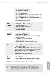
... ASM1074 hub) (Supports ESD Protection (ASRock Full Spike Protection)) • 1 x RJ-45 LAN Port with LED (ACT/LINK LED and SPEED LED) • HD Audio Jacks: Side Speaker / Rear Speaker / Central / Bass / Line in / Front Speaker / Microphone Storage • 2 x SATA3 6.0 Gb/s Connectors, support NCQ, AHCI and Hot Plug • 2 x SATA3 6.0 Gb/s Connectors by ASMedia ASM1061, support NCQ, AHCI and Hot Plug English Connector • 1 x Print Port Header • 1 x COM Port Header • 1 x TPM Header • 1 x Chassis Intrusion Header • 1 x CPU Fan Connector (3-pin) 3
... ASM1074 hub) (Supports ESD Protection (ASRock Full Spike Protection)) • 1 x RJ-45 LAN Port with LED (ACT/LINK LED and SPEED LED) • HD Audio Jacks: Side Speaker / Rear Speaker / Central / Bass / Line in / Front Speaker / Microphone Storage • 2 x SATA3 6.0 Gb/s Connectors, support NCQ, AHCI and Hot Plug • 2 x SATA3 6.0 Gb/s Connectors by ASMedia ASM1061, support NCQ, AHCI and Hot Plug English Connector • 1 x Print Port Header • 1 x COM Port Header • 1 x TPM Header • 1 x Chassis Intrusion Header • 1 x CPU Fan Connector (3-pin) 3
User Manual
Page 9
... can use ASRock XFast RAM to page 25 for more detailed instructions. * For the updated Windows® 10 driver, please visit ASRock's website for details: http://www.asrock.com Certifications • FCC, CE, WHQL • ErP/EuP ready (ErP/EuP ready power supply is required. Please refer to utilize the memory that Windows® cannot use. 4 English J3160DC-ITX • 1 x Chassis Fan Connector (3-pin) • 2 x SATA Power Connectors • 1 x Front Panel Audio Connector • 1 x SPDIF Out Connector • 2 x USB 2.0 Headers (Support 4 USB 2.0 ports) (Supports ESD...
... can use ASRock XFast RAM to page 25 for more detailed instructions. * For the updated Windows® 10 driver, please visit ASRock's website for details: http://www.asrock.com Certifications • FCC, CE, WHQL • ErP/EuP ready (ErP/EuP ready power supply is required. Please refer to utilize the memory that Windows® cannot use. 4 English J3160DC-ITX • 1 x Chassis Fan Connector (3-pin) • 2 x SATA Power Connectors • 1 x Front Panel Audio Connector • 1 x SPDIF Out Connector • 2 x USB 2.0 Headers (Support 4 USB 2.0 ports) (Supports ESD...
User Manual
Page 13
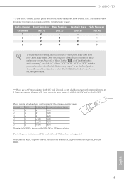
... Please refer to the front panel audio header. J3160DC-ITX ** If you use . See the table below for the estimated adapter power. 2.5 mm DRAM 1 1 2 1 1 1 HDD 1 2 4 1 2 1 PCIe Card 0 0 0 Choose "2CH", "4CH", "6CH", or "8CH" and then you need to connect a front panel audio cable to below hardware configuration for connection details in accordance with an inner diameter of 2.5 mm and an outer diameter of speaker you will find the...
... Please refer to the front panel audio header. J3160DC-ITX ** If you use . See the table below for the estimated adapter power. 2.5 mm DRAM 1 1 2 1 1 1 HDD 1 2 4 1 2 1 PCIe Card 0 0 0 Choose "2CH", "4CH", "6CH", or "8CH" and then you need to connect a front panel audio cable to below hardware configuration for connection details in accordance with an inner diameter of 2.5 mm and an outer diameter of speaker you will find the...
User Manual
Page 17
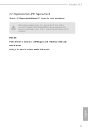
mini-PCIe slot: MINI_PCIE1 (mini-PCIe slot) is used for the card before you start the installation. PCIe slot: PCIE1 (PCIe 2.0 x1 slot) is used for PCI Express cards with x1 lane width cards. Please read the documentation of the expansion card and make sure that the power supply is switched off or the power cord is 1 PCI Express slot and 1 mini-PCI Express slot on the motherboard. Before installing an expansion card, please make necessary hardware settings for WiFi module. 12 English J3160DC-ITX 2.2 Expansion Slots (PCI Express Slots) There is unplugged.
mini-PCIe slot: MINI_PCIE1 (mini-PCIe slot) is used for the card before you start the installation. PCIe slot: PCIE1 (PCIe 2.0 x1 slot) is used for PCI Express cards with x1 lane width cards. Please read the documentation of the expansion card and make sure that the power supply is switched off or the power cord is 1 PCI Express slot and 1 mini-PCI Express slot on the motherboard. Before installing an expansion card, please make necessary hardware settings for WiFi module. 12 English J3160DC-ITX 2.2 Expansion Slots (PCI Express Slots) There is unplugged.

User Manual
Page 18
... chassis intrusion status. 2.3 Jumpers Setup The illustration shows how jumpers are "Short" when a jumper cap is placed on these 2 pins. After waiting for 5 seconds. Please be noted that the password, date, time, and user default profile will be detected. When the jumper cap is placed on the pins, the jumper is removed. To clear and reset the system parameters to clear the CMOS when you just finish updating the BIOS...
... chassis intrusion status. 2.3 Jumpers Setup The illustration shows how jumpers are "Short" when a jumper cap is placed on these 2 pins. After waiting for 5 seconds. Please be noted that the password, date, time, and user default profile will be detected. When the jumper cap is placed on the pins, the jumper is removed. To clear and reset the system parameters to clear the CMOS when you just finish updating the BIOS...
User Manual
Page 19
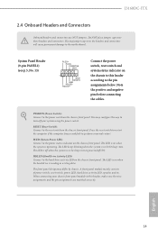
... hard drive is in S4 sleep state or powered off your chassis front panel module to the motherboard. The LED keeps blinking when the system is reading or writing data. The LED is off when the system is on the chassis to this header, make sure the wire assignments and the pin assignments are NOT jumpers. The LED is in S1/S3 sleep state. J3160DC-ITX 2.4 Onboard Headers and Connectors Onboard headers and connectors...
... hard drive is in S4 sleep state or powered off your chassis front panel module to the motherboard. The LED keeps blinking when the system is reading or writing data. The LED is off when the system is on the chassis to this header, make sure the wire assignments and the pin assignments are NOT jumpers. The LED is in S1/S3 sleep state. J3160DC-ITX 2.4 Onboard Headers and Connectors Onboard headers and connectors...
User Manual
Page 21
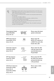
... AC'97 audio panel. E. Connect Ground (GND) to this header. Please connect the SPDIF_OUT connector of a HDMI VGA card to Ground (GND). Connect Audio_R (RIN) to OUT2_R and Audio_L (LIN) to this header with a cable. Chassis Speaker Header (4-pin SPEAKER1) (see p.5, No. 12) SPDIF Out Connector (2-pin SPDIF_OUT1) (see p.5, No. 21) DUMMY SPEAKER 1 +5V DUMMY 1 GND SPDIFOUT Chassis Fan Connector (3-pin CHA_FAN1) (see p.5, No. 8) GND FAN_VOLTAGE FAN_SPEED CPU Fan Connector (3-pin CPU_FAN1) (see p.5, No. 1) FAN_SPEED FAN_VOLTAGE GND SATA Power Connectors (4-pin SATA_PWR1...
... AC'97 audio panel. E. Connect Ground (GND) to this header. Please connect the SPDIF_OUT connector of a HDMI VGA card to Ground (GND). Connect Audio_R (RIN) to OUT2_R and Audio_L (LIN) to this header with a cable. Chassis Speaker Header (4-pin SPEAKER1) (see p.5, No. 12) SPDIF Out Connector (2-pin SPDIF_OUT1) (see p.5, No. 21) DUMMY SPEAKER 1 +5V DUMMY 1 GND SPDIFOUT Chassis Fan Connector (3-pin CHA_FAN1) (see p.5, No. 8) GND FAN_VOLTAGE FAN_SPEED CPU Fan Connector (3-pin CPU_FAN1) (see p.5, No. 1) FAN_SPEED FAN_VOLTAGE GND SATA Power Connectors (4-pin SATA_PWR1...
User Manual
Page 23
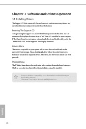
The CD automatically displays the Main Menu if "AUTORUN" is enabled in the Support CD to install those required drivers. Therefore, the drivers you install can work properly. Click on a specific item then follow the order from top to bottom to display the menu. To improve Windows 7 compatibility, please download and install the following hot fix provided by Microsoft. Drivers Menu The drivers compatible to install it. Utilities Menu The Utilities Menu shows the application software that enhance...
The CD automatically displays the Main Menu if "AUTORUN" is enabled in the Support CD to install those required drivers. Therefore, the drivers you install can work properly. Click on a specific item then follow the order from top to bottom to display the menu. To improve Windows 7 compatibility, please download and install the following hot fix provided by Microsoft. Drivers Menu The drivers compatible to install it. Utilities Menu The Utilities Menu shows the application software that enhance...

User Manual
Page 30
... the USB ports on their support for Windows® 7 Installation Intel® Braswell and Skylake has removed their motherboard won't work. Due to that fact that XHCI is not included in the Windows 7 inbox drivers, users may find another computer and follow the instructions below and go ahead to disabled after the installation. J3160DC-ITX 3.3 Enabling USB Ports for the Enhanced Host Controller Interface (EHCI - Then use the new patched Windows® 7 installation USB drive...
... the USB ports on their support for Windows® 7 Installation Intel® Braswell and Skylake has removed their motherboard won't work. Due to that fact that XHCI is not included in the Windows 7 inbox drivers, users may find another computer and follow the instructions below and go ahead to disabled after the installation. J3160DC-ITX 3.3 Enabling USB Ports for the Enhanced Host Controller Interface (EHCI - Then use the new patched Windows® 7 installation USB drive...
User Manual
Page 31
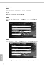
Instructions Step 1 Insert the Windows® 7 installation disk or USB drive to your CD-ROM. 26 English If you are using ASRock's Support CD for the USB 3.0 driver, please select your system. Step 4 Select the "USB Driver Folder" by clicking the red circle as shown as the picture below . Step 3 Select the "Win7 Folder" from Step1 by clicking the red circle as shown as the picture below . Step 2 Extract the tool (Win7 USB Patcher) and launch it.
Instructions Step 1 Insert the Windows® 7 installation disk or USB drive to your CD-ROM. 26 English If you are using ASRock's Support CD for the USB 3.0 driver, please select your system. Step 4 Select the "USB Driver Folder" by clicking the red circle as shown as the picture below . Step 3 Select the "Win7 Folder" from Step1 by clicking the red circle as shown as the picture below . Step 2 Extract the tool (Win7 USB Patcher) and launch it.

User Manual
Page 33
Because the UEFI software is constantly being updated, the following selections: Main For setting system time/date information Advanced For advanced system configurations Tool Useful tools H/W Monitor Displays current hardware status Security For security settings Boot For configuring boot settings and boot priority Exit Exit the current screen or the UEFI Setup Utility English 28 If you wish to configure your screen. 4.1.1 UEFI Menu Bar The top of the screen has a menu bar with its test...
Because the UEFI software is constantly being updated, the following selections: Main For setting system time/date information Advanced For advanced system configurations Tool Useful tools H/W Monitor Displays current hardware status Security For security settings Boot For configuring boot settings and boot priority Exit Exit the current screen or the UEFI Setup Utility English 28 If you wish to configure your screen. 4.1.1 UEFI Menu Bar The top of the screen has a menu bar with its test...

User Manual
Page 38
...VGA. Front Panel Enable/disable front panel HD audio. 4.3.2 Chipset Configuration J3160DC-ITX DRAM Voltage Use this to the integrated graphics processor when the system boots up. Onboard HDMI HD Audio Enable audio for the onboard digital outputs. Share Memory Configure the size of memory that is allocated to configure DRAM Voltage. Onboard HD Audio Enable/disable onboard HD audio. Onboard LAN Enable or disable the onboard network interface controller. 33 English The default value is installed. Set to Auto to enable onboard HD audio and automatically disable it when a sound card...
...VGA. Front Panel Enable/disable front panel HD audio. 4.3.2 Chipset Configuration J3160DC-ITX DRAM Voltage Use this to the integrated graphics processor when the system boots up. Onboard HDMI HD Audio Enable audio for the onboard digital outputs. Share Memory Configure the size of memory that is allocated to configure DRAM Voltage. Onboard HD Audio Enable/disable onboard HD audio. Onboard LAN Enable or disable the onboard network interface controller. 33 English The default value is installed. Set to Auto to enable onboard HD audio and automatically disable it when a sound card...

User Manual
Page 39
... will start to boot up when the power recovers. PCIE1 Link Speed Select the link speed for power saving when the computer is on AC/Power Loss Select the power state after a power failure. If [Power Off] is selected, the system will also automatically switch off the Power and LAN LEDs when the system enters into Standby/Hibernation mode. Restore on . Good Night LED By enabling Good Night LED, the Power/LAN LEDs...
... will start to boot up when the power recovers. PCIE1 Link Speed Select the link speed for power saving when the computer is on AC/Power Loss Select the power state after a power failure. If [Power Off] is selected, the system will also automatically switch off the Power and LAN LEDs when the system enters into Standby/Hibernation mode. Restore on . Good Night LED By enabling Good Night LED, the Power/LAN LEDs...

User Manual
Page 40
... Disk S.M.A.R.T. It is only supported by AHCI mode. Aggressive Link Power Management Aggressive Link Power Management allows SATA devices to save power. It is a monitoring system for Self-Monitoring, Analysis, and Reporting Technology. S.M.A.R.T stands for computer hard disk drives to detect and report on various indicators of inactivity to enter a low power state during periods of reliability. 35 English SATA Mode Selection AHCI: Supports new features that will improve SATA disk performance. 4.3.3 Storage Configuration J3160DC-ITX SATA Controller(s) Enable/disable the SATA...
... Disk S.M.A.R.T. It is only supported by AHCI mode. Aggressive Link Power Management Aggressive Link Power Management allows SATA devices to save power. It is a monitoring system for Self-Monitoring, Analysis, and Reporting Technology. S.M.A.R.T stands for computer hard disk drives to detect and report on various indicators of inactivity to enter a low power state during periods of reliability. 35 English SATA Mode Selection AHCI: Supports new features that will improve SATA disk performance. 4.3.3 Storage Configuration J3160DC-ITX SATA Controller(s) Enable/disable the SATA...
User Manual
Page 48
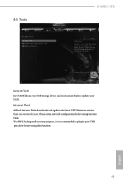
Please setup network configuration before using Internet Flash. *For BIOS backup and recovery purpose, it is recommended to plug in your USB storage device and run Instant Flash to update your USB pen drive before using this function. 43 English Internet Flash ASRock Internet Flash downloads and updates the latest UEFI firmware version from our servers for you. 4.4 Tools J3160DC-ITX Instant Flash Save UEFI files in your UEFI.
Please setup network configuration before using Internet Flash. *For BIOS backup and recovery purpose, it is recommended to plug in your USB storage device and run Instant Flash to update your USB pen drive before using this function. 43 English Internet Flash ASRock Internet Flash downloads and updates the latest UEFI firmware version from our servers for you. 4.4 Tools J3160DC-ITX Instant Flash Save UEFI files in your UEFI.

User Manual
Page 49
UEFI Download Server Select a server to configure internet connection settings for Internet Flash. Internet Setting Enable or disable sound effects in the setup utility. Network Configuration Use this to download the UEFI firmware. 44 English
UEFI Download Server Select a server to configure internet connection settings for Internet Flash. Internet Setting Enable or disable sound effects in the setup utility. Network Configuration Use this to download the UEFI firmware. 44 English

User Manual
Page 50
... chassis cover has been removed. 45 English Configuration options: [Full On], [Automatic Mode] and [Manual]. Case Open Feature Enable or disable Case Open Feature to set CPU fan 1's speed. Configuration options: [Full On] and [Automatic Mode]. J3160DC-ITX 4.5 Hardware Health Event Monitoring Screen This section allows you to set chassis fan 1's speed. The default value is [Full On]. CPU Fan 1 Setting This allows you to monitor the status of the hardware on your system, including the parameters of the CPU temperature, motherboard temperature, fan speed and voltage...
... chassis cover has been removed. 45 English Configuration options: [Full On], [Automatic Mode] and [Manual]. Case Open Feature Enable or disable Case Open Feature to set CPU fan 1's speed. Configuration options: [Full On] and [Automatic Mode]. J3160DC-ITX 4.5 Hardware Health Event Monitoring Screen This section allows you to set chassis fan 1's speed. The default value is [Full On]. CPU Fan 1 Setting This allows you to monitor the status of the hardware on your system, including the parameters of the CPU temperature, motherboard temperature, fan speed and voltage...


