
User Manual
Page 3
... 1.1 Package Contents 1 1.2 Specifications 2 1.3 Motherboard Layout 6 1.4 I/O Panel 8 1.5 WiFi-802.11n Module and ASRock WiFi 2.4GHz Antenna 9 Chapter 2 Installation 14 2.1 Installing the CPU 15 2.2 Installing the CPU Fan and Heatsink 18 2.3 Installing Memory Modules (DIMM) 19 2.4 Expansion Slots (PCI Express Slots) 21 2.5 Jumpers Setup 22 2.6 Onboard Headers and Connectors 23 Chapter 3 Software and Utilities Operation 27 3.1 Installing Drivers 27 3.2 A-Tuning 28 3.3 Intel® Smart Connect Technology 34 3.4 ASRock Cloud 39 3.5 ASRock APP Shop 49 3.5.1 UI...
... 1.1 Package Contents 1 1.2 Specifications 2 1.3 Motherboard Layout 6 1.4 I/O Panel 8 1.5 WiFi-802.11n Module and ASRock WiFi 2.4GHz Antenna 9 Chapter 2 Installation 14 2.1 Installing the CPU 15 2.2 Installing the CPU Fan and Heatsink 18 2.3 Installing Memory Modules (DIMM) 19 2.4 Expansion Slots (PCI Express Slots) 21 2.5 Jumpers Setup 22 2.6 Onboard Headers and Connectors 23 Chapter 3 Software and Utilities Operation 27 3.1 Installing Drivers 27 3.2 A-Tuning 28 3.3 Intel® Smart Connect Technology 34 3.4 ASRock Cloud 39 3.5 ASRock APP Shop 49 3.5.1 UI...

User Manual
Page 4
...Setting 54 3.6 Start8 55 Chapter 4 UEFI SETUP UTILITY 58 4.1 Introduction 58 4.1.1 UEFI Menu Bar 58 4.1.2 Navigation Keys 59 4.2 Main Screen 60 4.3 OC Tweaker Screen 61 4.4 Advanced Screen 69 4.4.1 CPU Configuration 70 4.4.2 Chipset Configuration 72 4.4.3 Storage Configuration 74 4.4.4 Intel® Smart Connect Technology 75 4.4.5 Super IO Configuration 76 4.4.6 ACPI Configuration 77 4.4.7 USB Configuration 79 4.4.8 Trusted Computing 81 4.5 Tools 82 4.6 Hardware Health Event Monitoring Screen 85 4.7 Boot Screen 86 4.8 Security Screen 89 4.9 Exit Screen...
...Setting 54 3.6 Start8 55 Chapter 4 UEFI SETUP UTILITY 58 4.1 Introduction 58 4.1.1 UEFI Menu Bar 58 4.1.2 Navigation Keys 59 4.2 Main Screen 60 4.3 OC Tweaker Screen 61 4.4 Advanced Screen 69 4.4.1 CPU Configuration 70 4.4.2 Chipset Configuration 72 4.4.3 Storage Configuration 74 4.4.4 Intel® Smart Connect Technology 75 4.4.5 Super IO Configuration 76 4.4.6 ACPI Configuration 77 4.4.7 USB Configuration 79 4.4.8 Trusted Computing 81 4.5 Tools 82 4.6 Hardware Health Event Monitoring Screen 85 4.7 Boot Screen 86 4.8 Security Screen 89 4.9 Exit Screen...

User Manual
Page 5
Chapter 4 contains the configuration guide of the software and utilities. You may find the latest VGA cards and CPU support list on ASRock's website without notice. In case any modifications of this documentation will be subject to change without further notice. ASRock website http://www.asrock.com. 1.1 Package Contents • ASRock H81M-ITX/WiFi Motherboard (Mini-ITX Form Factor) • ASRock H81M-ITX/WiFi Quick Installation Guide • ASRock H81M-ITX/WiFi Support CD • 1 x I/O Panel Shield • 2 x Serial ATA (SATA) Data Cables (Optional) • 1 x WiFi-802.11n...
Chapter 4 contains the configuration guide of the software and utilities. You may find the latest VGA cards and CPU support list on ASRock's website without notice. In case any modifications of this documentation will be subject to change without further notice. ASRock website http://www.asrock.com. 1.1 Package Contents • ASRock H81M-ITX/WiFi Motherboard (Mini-ITX Form Factor) • ASRock H81M-ITX/WiFi Quick Installation Guide • ASRock H81M-ITX/WiFi Support CD • 1 x I/O Panel Shield • 2 x Serial ATA (SATA) Data Cables (Optional) • 1 x WiFi-802.11n...

User Manual
Page 8
..., support NCQ, AHCI and Hot Plug Connector • 1 x Chassis Intrusion Header • 1 x TPM Header • 1 x CPU Fan Connector (4-pin) • 1 x Chassis Fan Connector (4-pin) • 1 x 24 pin ATX Power Connector • 1 x 4 pin 12V Power Connector • 1 x Front Panel Audio Connector • 2 x USB 2.0 Headers (Support 4 USB 2.0 ports) (Supports ESD Protection (ASRock Full Spike Protection)) BIOS Feature • 32Mb AMI UEFI Legal BIOS with multilingual GUI support • ACPI 1.1 Compliant wake up events • SMBIOS 2.3.1 support • CPU, DRAM, PCH 1.05V Voltage...
..., support NCQ, AHCI and Hot Plug Connector • 1 x Chassis Intrusion Header • 1 x TPM Header • 1 x CPU Fan Connector (4-pin) • 1 x Chassis Fan Connector (4-pin) • 1 x 24 pin ATX Power Connector • 1 x 4 pin 12V Power Connector • 1 x Front Panel Audio Connector • 2 x USB 2.0 Headers (Support 4 USB 2.0 ports) (Supports ESD Protection (ASRock Full Spike Protection)) BIOS Feature • 32Mb AMI UEFI Legal BIOS with multilingual GUI support • ACPI 1.1 Compliant wake up events • SMBIOS 2.3.1 support • CPU, DRAM, PCH 1.05V Voltage...

User Manual
Page 10
1.3 Motherboard Layout PS2 Keyboard /Mouse HDMI1 USB 2.0 T: USB2 B: USB3 CPU_FAN1 ATX12V1 DVI1 VGA1 CHA_FAN1 USB 3.0 T: USB1 B: USB2 CMOS Battery USB 2.0 T: USB0 B: USB1 Top: RJ-45 HD_AUDIO1 1 Audio CODEC Intel H81 RoHS H81M-ITX/WiFi MPCIE1 USB 3.0 SATA_3 SATA_2 SATA3_1 SATA3_0 USB_4_5 32Mb BIOS 1 PCIE1 DDR3_A1 (64 bit, 240-pin module) DDR3_B1 (64 bit, 240-pin module) ATXPWR1 CLRCMOS1 1 CI1 1 1 TPMS1 1 1 USB_6_7 PANEL1 Top: LINE IN Center: FRONT Bottom: MIC IN PLED PWRBTN HDLED RESET English 6
1.3 Motherboard Layout PS2 Keyboard /Mouse HDMI1 USB 2.0 T: USB2 B: USB3 CPU_FAN1 ATX12V1 DVI1 VGA1 CHA_FAN1 USB 3.0 T: USB1 B: USB2 CMOS Battery USB 2.0 T: USB0 B: USB1 Top: RJ-45 HD_AUDIO1 1 Audio CODEC Intel H81 RoHS H81M-ITX/WiFi MPCIE1 USB 3.0 SATA_3 SATA_2 SATA3_1 SATA3_0 USB_4_5 32Mb BIOS 1 PCIE1 DDR3_A1 (64 bit, 240-pin module) DDR3_B1 (64 bit, 240-pin module) ATXPWR1 CLRCMOS1 1 CI1 1 1 TPMS1 1 1 USB_6_7 PANEL1 Top: LINE IN Center: FRONT Bottom: MIC IN PLED PWRBTN HDLED RESET English 6

User Manual
Page 11
Description 1 CPU Fan Connector (CPU_FAN1) 2 ATX 12V Power Connector (ATX12V1) 3 2 x 240-pin DDR3 DIMM Slots (DDR3_A1, DDR3_B1) 4 Clear CMOS Jumper (CLRCMOS1) 5 Chassis Intrusion Header (CI1) 6 ATX Power Connector (ATXPWR1) 7 TPM Header (TPMS1) 8 USB 2.0 Header (USB_6_7) 9 System Panel Header (PANEL1) 10 USB 2.0 Header (USB_4_5) 11 SATA3 Connector (SATA3_0) 12 SATA3 Connector (SATA3_1) 13 SATA2 Connector (SATA_2) 14 SATA2 Connector (SATA_3) 15 Front Panel Audio Header (HD_AUDIO1) 16 Chassis Fan Connector (CHA_FAN1) H81M-ITX/WiFi English 7 No.
Description 1 CPU Fan Connector (CPU_FAN1) 2 ATX 12V Power Connector (ATX12V1) 3 2 x 240-pin DDR3 DIMM Slots (DDR3_A1, DDR3_B1) 4 Clear CMOS Jumper (CLRCMOS1) 5 Chassis Intrusion Header (CI1) 6 ATX Power Connector (ATXPWR1) 7 TPM Header (TPMS1) 8 USB 2.0 Header (USB_6_7) 9 System Panel Header (PANEL1) 10 USB 2.0 Header (USB_4_5) 11 SATA3 Connector (SATA3_0) 12 SATA3 Connector (SATA3_1) 13 SATA2 Connector (SATA_2) 14 SATA2 Connector (SATA_3) 15 Front Panel Audio Header (HD_AUDIO1) 16 Chassis Fan Connector (CHA_FAN1) H81M-ITX/WiFi English 7 No.

User Manual
Page 26
... seconds, use a jumper cap to short pin2 and pin3 on the pins, the jumper is "Short". After waiting for 5 seconds. Please adjust the BIOS option "Clear Status" to clear the data in CMOS. Clear CMOS Jumper (CLRCMOS1) (see p.6, No. 4) Default Clear CMOS CLRCMOS1 allows you need to default setup, please turn off the computer and unplug the power cord from the power supply. If you to clear the record of previous chassis intrusion status. 2.5 Jumpers Setup The...
... seconds, use a jumper cap to short pin2 and pin3 on the pins, the jumper is "Short". After waiting for 5 seconds. Please adjust the BIOS option "Clear Status" to clear the data in CMOS. Clear CMOS Jumper (CLRCMOS1) (see p.6, No. 4) Default Clear CMOS CLRCMOS1 allows you need to default setup, please turn off the computer and unplug the power cord from the power supply. If you to clear the record of previous chassis intrusion status. 2.5 Jumpers Setup The...

User Manual
Page 29
... power supply to the ground pin. H81M-ITX/WiFi Chassis Fan Connector (4-pin CHA_FAN1) (see p.6, No. 16) 1 GND Please connect fan cable 2 +12V 3 FAN_SPEED to the fan connector and 4 FAN_SPEED_CONTROL match the black wire to this connector. English 25 This feature requires a chassis with chassis intrusion detection design. CPU Fan Connector (4-pin CPU_FAN1) (see p.6, No. 6) 12 24 1 13 This motherboard provides a 24-pin ATX power connector. ATX Power Connector (24-pin ATXPWR1) (see p.6, No. 1) This motherboard pro- 1 GND 2 +12V vides a 4-Pin CPU fan...
... power supply to the ground pin. H81M-ITX/WiFi Chassis Fan Connector (4-pin CHA_FAN1) (see p.6, No. 16) 1 GND Please connect fan cable 2 +12V 3 FAN_SPEED to the fan connector and 4 FAN_SPEED_CONTROL match the black wire to this connector. English 25 This feature requires a chassis with chassis intrusion detection design. CPU Fan Connector (4-pin CPU_FAN1) (see p.6, No. 6) 12 24 1 13 This motherboard provides a 24-pin ATX power connector. ATX Power Connector (24-pin ATXPWR1) (see p.6, No. 1) This motherboard pro- 1 GND 2 +12V vides a 4-Pin CPU fan...

User Manual
Page 31
... a specific item then follow the order from top to bottom to display the menu. To improve Windows 7 compatibility, please download and install the following hot fix provided by Microsoft. Therefore, the drivers you install can work properly. Please click Install All or follow the installation wizard to your system will be auto-detected and listed on the file "ASRSETUP.EXE" in your CD-ROM drive. H81M-ITX/WiFi Chapter 3 Software and Utilities...
... a specific item then follow the order from top to bottom to display the menu. To improve Windows 7 compatibility, please download and install the following hot fix provided by Microsoft. Therefore, the drivers you install can work properly. Please click Install All or follow the installation wizard to your system will be auto-detected and listed on the file "ASRSETUP.EXE" in your CD-ROM drive. H81M-ITX/WiFi Chapter 3 Software and Utilities...

User Manual
Page 38
... AHCI. 3.3 Intel® Smart Connect Technology Intel® Smart Connect Technology is a feature that periodically wakes your system is already installed under IDE mode, directly changing the SATA mode to AHCI may cause Windows 8.1/8/7 to crash while booting. If Windows 8.1/8/7 is not in Windows Registry Editor. or 64-bit edition) • Set the SATA mode to avoid loss. 1. Double click on OK. 34 English Click on the value Start and change the value from Windows® sleep...
... AHCI. 3.3 Intel® Smart Connect Technology Intel® Smart Connect Technology is a feature that periodically wakes your system is already installed under IDE mode, directly changing the SATA mode to AHCI may cause Windows 8.1/8/7 to crash while booting. If Windows 8.1/8/7 is not in Windows Registry Editor. or 64-bit edition) • Set the SATA mode to avoid loss. 1. Double click on OK. 34 English Click on the value Start and change the value from Windows® sleep...

User Manual
Page 43
.... H81M-ITX/WiFi 3.4 ASRock Cloud ASRock Cloud makes your mobile devices connect to power your PC on Windows 8.1 / 7. 39 English ASRock Cloud includes several technologies and software solutions for remotely controlling your computer, even if the computer is supported on or turn it remotely with a Realtek® LAN chip, ASRock Cloud allows users to remotely wake up and control their computers, or they could wake up their computers via the internet by using...
.... H81M-ITX/WiFi 3.4 ASRock Cloud ASRock Cloud makes your mobile devices connect to power your PC on Windows 8.1 / 7. 39 English ASRock Cloud includes several technologies and software solutions for remotely controlling your computer, even if the computer is supported on or turn it remotely with a Realtek® LAN chip, ASRock Cloud allows users to remotely wake up and control their computers, or they could wake up their computers via the internet by using...

User Manual
Page 62
... sound effects and stunning visuals. Not only will continue with the following selections: Main For setting system time/date information OC Tweaker For overclocking configurations Advanced For advanced system configurations Tool Useful tools H/W Monitor Displays current hardware status Boot For configuring boot settings and boot priority Security For security settings Exit Exit the current screen or the UEFI Setup Utility 58 English You may also restart by pressing the reset button...
... sound effects and stunning visuals. Not only will continue with the following selections: Main For setting system time/date information OC Tweaker For overclocking configurations Advanced For advanced system configurations Tool Useful tools H/W Monitor Displays current hardware status Boot For configuring boot settings and boot priority Security For security settings Exit Exit the current screen or the UEFI Setup Utility 58 English You may also restart by pressing the reset button...
User Manual
Page 65
... overclocking may cause damage to your CPU and motherboard. It should be done at your own risk and expense. Non-Z OC Non-Z OC allows users with a K-Series Haswell processor to your GPU and motherboard. 4.3 OC Tweaker Screen In the OC Tweaker screen, you see on your own risk and expense. 61 English H81M-ITX/WiFi Because the UEFI software is constantly being updated, the following UEFI setup screens...
... overclocking may cause damage to your CPU and motherboard. It should be done at your own risk and expense. Non-Z OC Non-Z OC allows users with a K-Series Haswell processor to your GPU and motherboard. 4.3 OC Tweaker Screen In the OC Tweaker screen, you see on your own risk and expense. 61 English H81M-ITX/WiFi Because the UEFI software is constantly being updated, the following UEFI setup screens...

User Manual
Page 76
... a primary VGA. VT-d Intel® Virtualization Technology for Directed I /O performance. IGPU Multi-Monitor Select disable to keep the integrated graphics enabled at all times. Select enable to disable the integrated graphics when an external graphics card is idle for PCIE1. PCIE1 Link Speed Select the link speed for lower power consumption. 72 English Share Memory Configure the size of manageability, security, isolation, and I /O helps your virtual machine monitor better utilize hardware...
... a primary VGA. VT-d Intel® Virtualization Technology for Directed I /O performance. IGPU Multi-Monitor Select disable to keep the integrated graphics enabled at all times. Select enable to disable the integrated graphics when an external graphics card is idle for PCIE1. PCIE1 Link Speed Select the link speed for lower power consumption. 72 English Share Memory Configure the size of manageability, security, isolation, and I /O helps your virtual machine monitor better utilize hardware...

User Manual
Page 77
... be switched off when the power recovers. Good Night LED By enabling Good Night LED, the Power/HDD LEDs will start to enable onboard HD audio and automatically disable it when a sound card is shut down. H81M-ITX/WiFi Onboard HD Audio Enable/disable onboard HD audio. Restore on . If [Power On] is on AC/Power Loss Select the power state after a power failure. Onboard LAN Enable or disable the onboard network interface controller. Deep Sleep Configure deep sleep mode for power saving when the computer is installed. WAN1 Radio Enable or disable the connectivity...
... be switched off when the power recovers. Good Night LED By enabling Good Night LED, the Power/HDD LEDs will start to enable onboard HD audio and automatically disable it when a sound card is shut down. H81M-ITX/WiFi Onboard HD Audio Enable/disable onboard HD audio. Restore on . If [Power On] is on AC/Power Loss Select the power state after a power failure. Onboard LAN Enable or disable the onboard network interface controller. Deep Sleep Configure deep sleep mode for power saving when the computer is installed. WAN1 Radio Enable or disable the connectivity...

User Manual
Page 83
... controller mode. Select UEFI Setup Only to keep the USB 3.0 driver enabled (Must install driver to support USB devices under Windows® 7). Legacy USB Support Enable or disable Legacy OS Support for USB 3.0 devices. Set [Enabled] to keep the USB 3.0 driver enabled after entering the OS (USB 3.0 is recommended to disable legacy USB support. Select UEFI Setup Only to use USB devices under the UEFI setup and Windows/Linux operating systems only. 4.4.7 USB Configuration H81M-ITX/WiFi USB Controller Enable or disable all the USB ports. Legacy USB 3.0 Support Enable or disable...
... controller mode. Select UEFI Setup Only to keep the USB 3.0 driver enabled (Must install driver to support USB devices under Windows® 7). Legacy USB Support Enable or disable Legacy OS Support for USB 3.0 devices. Set [Enabled] to keep the USB 3.0 driver enabled after entering the OS (USB 3.0 is recommended to disable legacy USB support. Select UEFI Setup Only to use USB devices under the UEFI setup and Windows/Linux operating systems only. 4.4.7 USB Configuration H81M-ITX/WiFi USB Controller Enable or disable all the USB ports. Legacy USB 3.0 Support Enable or disable...
User Manual
Page 86
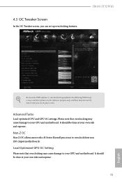
...Please setup network configuration before using Internet Flash. *For BIOS backup and recovery purpose, it is a handy tool in your system via an USB storage device, then downloads and installs the other required drivers automatically. Please setup network configuration before using UEFI Tech Service. Easy Driver Installer For users that installs the LAN driver to your USB pen drive before using this to install the drivers from our servers for Internet Flash. 82 English Internet Flash ASRock Internet Flash downloads and updates the latest UEFI firmware version from our support...
...Please setup network configuration before using Internet Flash. *For BIOS backup and recovery purpose, it is a handy tool in your system via an USB storage device, then downloads and installs the other required drivers automatically. Please setup network configuration before using UEFI Tech Service. Easy Driver Installer For users that installs the LAN driver to your USB pen drive before using this to install the drivers from our servers for Internet Flash. 82 English Internet Flash ASRock Internet Flash downloads and updates the latest UEFI firmware version from our support...
Quick Installation Guide
Page 11
... stringent quality control. ASRock website http://www.asrock.com. 1.1 Package Contents • ASRock H81M-ITX/WiFi Motherboard (Mini-ITX Form Factor) • ASRock H81M-ITX/WiFi Quick Installation Guide • ASRock H81M-ITX/WiFi Support CD • 1 x I/O Panel Shield • 2 x Serial ATA (SATA) Data Cables (Optional) • 1 x WiFi-802.11n Module • 1 x SMA WiFi Antenna Cable • 1 x ASRock WiFi 2.4 GHz Antenna • 1 x WiFi Module Bracket • 2 x Screws for WiFi Module 9 English Because the motherboard specifications and the BIOS software might be updated, the...
... stringent quality control. ASRock website http://www.asrock.com. 1.1 Package Contents • ASRock H81M-ITX/WiFi Motherboard (Mini-ITX Form Factor) • ASRock H81M-ITX/WiFi Quick Installation Guide • ASRock H81M-ITX/WiFi Support CD • 1 x I/O Panel Shield • 2 x Serial ATA (SATA) Data Cables (Optional) • 1 x WiFi-802.11n Module • 1 x SMA WiFi Antenna Cable • 1 x ASRock WiFi 2.4 GHz Antenna • 1 x WiFi Module Bracket • 2 x Screws for WiFi Module 9 English Because the motherboard specifications and the BIOS software might be updated, the...

Quick Installation Guide
Page 14
..., support NCQ, AHCI and Hot Plug Connector • 1 x Chassis Intrusion Header • 1 x TPM Header • 1 x CPU Fan Connector (4-pin) • 1 x Chassis Fan Connector (4-pin) • 1 x 24 pin ATX Power Connector • 1 x 4 pin 12V Power Connector • 1 x Front Panel Audio Connector • 2 x USB 2.0 Headers (Support 4 USB 2.0 ports) (Supports ESD Protection (ASRock Full Spike Protection)) BIOS Feature • 32Mb AMI UEFI Legal BIOS with multilingual GUI support • ACPI 1.1 Compliant wake up events • SMBIOS 2.3.1 support • CPU, DRAM, PCH 1.05V Voltage...
..., support NCQ, AHCI and Hot Plug Connector • 1 x Chassis Intrusion Header • 1 x TPM Header • 1 x CPU Fan Connector (4-pin) • 1 x Chassis Fan Connector (4-pin) • 1 x 24 pin ATX Power Connector • 1 x 4 pin 12V Power Connector • 1 x Front Panel Audio Connector • 2 x USB 2.0 Headers (Support 4 USB 2.0 ports) (Supports ESD Protection (ASRock Full Spike Protection)) BIOS Feature • 32Mb AMI UEFI Legal BIOS with multilingual GUI support • ACPI 1.1 Compliant wake up events • SMBIOS 2.3.1 support • CPU, DRAM, PCH 1.05V Voltage...

Quick Installation Guide
Page 24
... the power supply. If no jumper cap is placed on the pins, the jumper is "Short". After waiting for 5 seconds. Please be noted that the password, date, time, and user default profile will be detected. 2.5 Jumpers Setup The illustration shows how jumpers are "Short" when a jumper cap is placed on these 2 pins. If you need to clear the record of previous chassis intrusion status. Please adjust the BIOS option "Clear...
... the power supply. If no jumper cap is placed on the pins, the jumper is "Short". After waiting for 5 seconds. Please be noted that the password, date, time, and user default profile will be detected. 2.5 Jumpers Setup The illustration shows how jumpers are "Short" when a jumper cap is placed on these 2 pins. If you need to clear the record of previous chassis intrusion status. Please adjust the BIOS option "Clear...


