
User Manual
Page 5
... BIOS sotware might be updated, the content of this manual, Chapter 1 and 2 contains the introduction of the sotware and utilities. In case any modiications of the BIOS setup. You may ind the latest VGA cards and CPU support list on ASRock's website without notice. H81M-HDS R2.0 Chapter 1 Introduction hank you are using. Chapter 3 contains...
... BIOS sotware might be updated, the content of this manual, Chapter 1 and 2 contains the introduction of the sotware and utilities. In case any modiications of the BIOS setup. You may ind the latest VGA cards and CPU support list on ASRock's website without notice. H81M-HDS R2.0 Chapter 1 Introduction hank you are using. Chapter 3 contains...
User Manual
Page 24
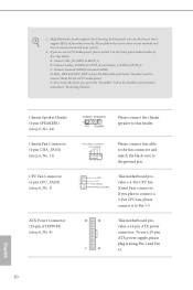
...Recording Volume". Connect Audio_R (RIN) to OUT2_R and Audio_L (LIN) to MIC2_L. To activate the front mic, go to the "FrontMic" Tab in our manual and chassis manual to this header. Chassis Speaker Header (4-pin SPEAKER1) (see p.6, No. 1) 1 GND his motherboard provides a 24-pin ATX power connector. CPU Fan ...plug it along Pin 1 and Pin 13. 20 English To use an AC'97 audio panel, please install it to connect them for the HD audio panel only. High Deinition Audio supports Jack Sensing, but the panel wire on the chassis must support HDA to Ground (GND). You ...
...Recording Volume". Connect Audio_R (RIN) to OUT2_R and Audio_L (LIN) to MIC2_L. To activate the front mic, go to the "FrontMic" Tab in our manual and chassis manual to this header. Chassis Speaker Header (4-pin SPEAKER1) (see p.6, No. 1) 1 GND his motherboard provides a 24-pin ATX power connector. CPU Fan ...plug it along Pin 1 and Pin 13. 20 English To use an AC'97 audio panel, please install it to connect them for the HD audio panel only. High Deinition Audio supports Jack Sensing, but the panel wire on the chassis must support HDA to Ground (GND). You ...
User Manual
Page 54
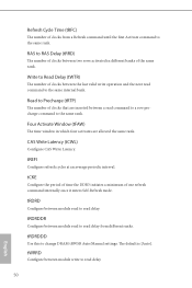
... are inserted between a read command to a row precharge command to read delay from a Refresh command until the irst Activate command to change DRAM tRWSR Auto/Manual settings. RAS to read to the same rank. tWRRD Conigure between module write to RAS Delay (tRRD) he default is [Auto].
... are inserted between a read command to a row precharge command to read delay from a Refresh command until the irst Activate command to change DRAM tRWSR Auto/Manual settings. RAS to read to the same rank. tWRRD Conigure between module write to RAS Delay (tRRD) he default is [Auto].
User Manual
Page 55
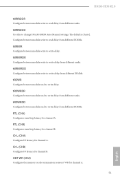
... latency for channel A. IO-L (CHB) Conigure IO latency for channel A. 51 English ODT WR (CHA) Conigure the memory on die termination resistors' WR for channel B. H81M-HDS R2.0 tWRRDDR Conigure between module write to write delay from diferent ranks. Conigure between module write to read delay from diferent DIMMs. tWRWR Conigure between module... read delay from diferent ranks. he default is [Auto]. tRDWRDR Conigure between module write to change DRAM tRRSR Auto/Manual settings. tWRRDDD Use this to write delay.
... latency for channel A. IO-L (CHB) Conigure IO latency for channel A. 51 English ODT WR (CHA) Conigure the memory on die termination resistors' WR for channel B. H81M-HDS R2.0 tWRRDDR Conigure between module write to write delay from diferent ranks. Conigure between module write to read delay from diferent DIMMs. tWRWR Conigure between module... read delay from diferent ranks. he default is [Auto]. tRDWRDR Conigure between module write to change DRAM tRRSR Auto/Manual settings. tWRRDDD Use this to write delay.
User Manual
Page 56
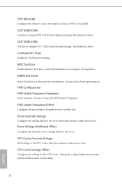
... the Vcore when the system is under heavy load. ODT NOM (CHA) Use this to change ODT (CHB) Auto/Manual settings. ODT NOM (CHB) Use this to change ODT (CHA) Auto/Manual settings. MRC Fast Boot Enable Memory Fast Boot to reduce power consumption, or Fast Exit for better performance. CPU Cache...
... the Vcore when the system is under heavy load. ODT NOM (CHA) Use this to change ODT (CHB) Auto/Manual settings. ODT NOM (CHB) Use this to change ODT (CHA) Auto/Manual settings. MRC Fast Boot Enable Memory Fast Boot to reduce power consumption, or Fast Exit for better performance. CPU Cache...
Quick Installation Guide
Page 14
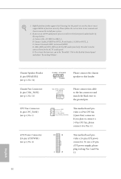
... use a 20-pin ATX power supply, please plug it along Pin 1 and Pin 13. 12 English Connect Mic_IN (MIC) to connect them for the HD audio panel only. Connect Audio_R (RIN) to OUT2_R and Audio_L (LIN) to this header. E. Chassis Speaker Header (4-pin SPEAKER1) (see p.1, No. .... High Deinition Audio supports Jack Sensing, but the panel wire on the chassis must support HDA to the "FrontMic" Tab in our manual and chassis manual to the ground pin. Please follow the instructions in the Realtek Control panel and adjust "Recording Volume". Chassis Fan Connector (4-pin CHA_FAN1)...
... use a 20-pin ATX power supply, please plug it along Pin 1 and Pin 13. 12 English Connect Mic_IN (MIC) to connect them for the HD audio panel only. Connect Audio_R (RIN) to OUT2_R and Audio_L (LIN) to this header. E. Chassis Speaker Header (4-pin SPEAKER1) (see p.1, No. .... High Deinition Audio supports Jack Sensing, but the panel wire on the chassis must support HDA to the "FrontMic" Tab in our manual and chassis manual to the ground pin. Please follow the instructions in the Realtek Control panel and adjust "Recording Volume". Chassis Fan Connector (4-pin CHA_FAN1)...
