
User Manual
Page 3
... Contents 1 1.2 Speciications 2 1.3 Motherboard Layout 6 1.4 I/O Panel 8 Chapter 2 Installation 9 2.1 Installing the CPU 10 2.2 Installing the CPU Fan and Heatsink 13 2.3 Installing Memory Modules (DIMM) 14 2.4 Expansion Slots (PCI Express Slots) 16 2.5 Jumpers Setup 17 2.6 Onboard Headers and Connectors 18 Chapter 3 Software and Utilities Operation 23 3.1 Installing Drivers 23 3.2 A-Tuning 24 3.3 Intel® Smart Connect Technology 30 3.4 ASRock APP Shop 35 3.4.1 UI Overview 35 3.4.2 Apps 36 3.4.3 BIOS & Drivers 39 3.4.4 Setting 40 3.5 Start8 41
... Contents 1 1.2 Speciications 2 1.3 Motherboard Layout 6 1.4 I/O Panel 8 Chapter 2 Installation 9 2.1 Installing the CPU 10 2.2 Installing the CPU Fan and Heatsink 13 2.3 Installing Memory Modules (DIMM) 14 2.4 Expansion Slots (PCI Express Slots) 16 2.5 Jumpers Setup 17 2.6 Onboard Headers and Connectors 18 Chapter 3 Software and Utilities Operation 23 3.1 Installing Drivers 23 3.2 A-Tuning 24 3.3 Intel® Smart Connect Technology 30 3.4 ASRock APP Shop 35 3.4.1 UI Overview 35 3.4.2 Apps 36 3.4.3 BIOS & Drivers 39 3.4.4 Setting 40 3.5 Start8 41
User Manual
Page 5
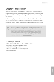
... are using. ASRock website http://www.asrock.com. 1.1 Package Contents • ASRock H81M-G Motherboard (Micro ATX Form Factor) • ASRock H81M-G Quick Installation Guide • ASRock H81M-G Support CD • 2 x Serial ATA (SATA) Data Cables (Optional) • 1 x I/O Panel Shield 1 English Because the motherboard speciications and the BIOS sotware might be updated, the content of this manual, Chapter 1 and 2 contains the introduction of the motherboard and step-by-step installation guides. In this documentation occur, the updated version will...
... are using. ASRock website http://www.asrock.com. 1.1 Package Contents • ASRock H81M-G Motherboard (Micro ATX Form Factor) • ASRock H81M-G Quick Installation Guide • ASRock H81M-G Support CD • 2 x Serial ATA (SATA) Data Cables (Optional) • 1 x I/O Panel Shield 1 English Because the motherboard speciications and the BIOS sotware might be updated, the content of this manual, Chapter 1 and 2 contains the introduction of the motherboard and step-by-step installation guides. In this documentation occur, the updated version will...

User Manual
Page 8
... 3-pin) • 2 x Chassis Fan Connectors (1 x 4-pin, 1 x 3-pin) • 1 x Power Fan Connector (3-pin) • 1 x 24 pin ATX Power Connector • 1 x 8 pin 12V Power Connector • 1 x PCIe Power Connector • 1 x Front Panel Audio Connector • 1 x USB Power Jumper (Ultra USB Power) • 2 x USB 2.0 Headers (Support 4 USB 2.0 ports) (Supports ESD Protection (ASRock Full Spike Protection)) • 32Mb AMI UEFI Legal BIOS with multilingual GUI support • ACPI 1.1 Compliant wake up events • SMBIOS 2.3.1 support • CPU, DRAM, PCH 1.05V, PCH 1.5V Voltage multi...
... 3-pin) • 2 x Chassis Fan Connectors (1 x 4-pin, 1 x 3-pin) • 1 x Power Fan Connector (3-pin) • 1 x 24 pin ATX Power Connector • 1 x 8 pin 12V Power Connector • 1 x PCIe Power Connector • 1 x Front Panel Audio Connector • 1 x USB Power Jumper (Ultra USB Power) • 2 x USB 2.0 Headers (Support 4 USB 2.0 ports) (Supports ESD Protection (ASRock Full Spike Protection)) • 32Mb AMI UEFI Legal BIOS with multilingual GUI support • ACPI 1.1 Compliant wake up events • SMBIOS 2.3.1 support • CPU, DRAM, PCH 1.05V, PCH 1.5V Voltage multi...

User Manual
Page 20
... 4 PCI Express slots on the motherboard. Please connect a 4 pin molex power cable to the motherboard's chassis fan connector (CHA_FAN1 or CHA_FAN2) when using multiple graphics cards. 2. PCIE2 (PCIe 2.0 x1 slot) is unplugged. Before installing an expansion card, please make necessary hardware settings for the card before you start the installation. Please read the documentation of the expansion card and make sure that the power supply is switched of or the power cord is used for PCI Express x1 lane width cards. 2.4 Expansion Slots (PCI Express Slots...
... 4 PCI Express slots on the motherboard. Please connect a 4 pin molex power cable to the motherboard's chassis fan connector (CHA_FAN1 or CHA_FAN2) when using multiple graphics cards. 2. PCIE2 (PCIe 2.0 x1 slot) is unplugged. Before installing an expansion card, please make necessary hardware settings for the card before you start the installation. Please read the documentation of the expansion card and make sure that the power supply is switched of or the power cord is used for PCI Express x1 lane width cards. 2.4 Expansion Slots (PCI Express Slots...

User Manual
Page 21
... are setup. Clear CMOS Jumper (CLRCMOS1) (see p.6, No. 1) +5V (Default) +5VSB USB Power Jumper is speciically designed for users who use a jumper cap to default setup, please turn of the computer and unplug the power cord from the power supply. However, please do not clear the CMOS right ater you do the clear-CMOS action. If you need to clear the data in standby mode. 17 English Pin 2-3 shorted: +5VSB voltage is provided for LED keyboard / mouse. H81M-G 2.5 Jumpers Setup he...
... are setup. Clear CMOS Jumper (CLRCMOS1) (see p.6, No. 1) +5V (Default) +5VSB USB Power Jumper is speciically designed for users who use a jumper cap to default setup, please turn of the computer and unplug the power cord from the power supply. However, please do not clear the CMOS right ater you do the clear-CMOS action. If you need to clear the data in standby mode. 17 English Pin 2-3 shorted: +5VSB voltage is provided for LED keyboard / mouse. H81M-G 2.5 Jumpers Setup he...
User Manual
Page 24
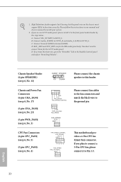
...'97 audio panel, please install it to the "FrontMic" Tab in our manual and chassis manual to MIC2_L. C. To activate the front mic, go to Pin 1-3. High Deinition Audio supports Jack Sensing, but the panel wire on the chassis must support HDA to the front panel audio header by the steps below: A. 1. If you plan to connect a 3-Pin CPU fan, please connect it to function correctly. Chassis Speaker Header (4-pin SPEAKER1) (see p.6, No. 12) Chassis and Power Fan Connectors (4-pin CHA_FAN1...
...'97 audio panel, please install it to the "FrontMic" Tab in our manual and chassis manual to MIC2_L. C. To activate the front mic, go to Pin 1-3. High Deinition Audio supports Jack Sensing, but the panel wire on the chassis must support HDA to the front panel audio header by the steps below: A. 1. If you plan to connect a 3-Pin CPU fan, please connect it to function correctly. Chassis Speaker Header (4-pin SPEAKER1) (see p.6, No. 12) Chassis and Power Fan Connectors (4-pin CHA_FAN1...

User Manual
Page 25
... use a 20-pin ATX power supply, please plug it along Pin 1 and Pin 13. 8 5 his motherboard pro- H81M-G ATX Power Connector (24-pin ATXPWR1) (see p.6, No. 7) ATX 12V Power Connector (8-pin ATX12V1) (see p.6, No. 2) PCIe Power Connector (4-pin PCIE_PWR1) (see p.6, No. 22) Serial Port Header (9-pin COM1) (see p.6, No. 19) 1 PCICLK FRAME PCIRST# LAD3 +3V LAD0 +3VSB GND GND SMB_CLK_MAIN SMB_DATA_MAIN LAD2 LAD1 GND S_PWRDWN# SERIRQ# GND his connector supports Trusted Platform Module (TPM) system, which can securely store keys...
... use a 20-pin ATX power supply, please plug it along Pin 1 and Pin 13. 8 5 his motherboard pro- H81M-G ATX Power Connector (24-pin ATXPWR1) (see p.6, No. 7) ATX 12V Power Connector (8-pin ATX12V1) (see p.6, No. 2) PCIe Power Connector (4-pin PCIE_PWR1) (see p.6, No. 22) Serial Port Header (9-pin COM1) (see p.6, No. 19) 1 PCICLK FRAME PCIRST# LAD3 +3V LAD0 +3VSB GND GND SMB_CLK_MAIN SMB_DATA_MAIN LAD2 LAD1 GND S_PWRDWN# SERIRQ# GND his connector supports Trusted Platform Module (TPM) system, which can securely store keys...

User Manual
Page 27
... install those required drivers. herefore, the drivers you install can work properly. Click on the ile "ASRSETUP.EXE" in your CD-ROM drive. If the Main Menu does not appear automatically, locate and double click on a speciic item then follow the order from top to bottom to display the menu. Utilities Menu he Utilities Menu shows the application sotware that enhance the motherboard's features. To improve Windows 7 compatibility, please download...
... install those required drivers. herefore, the drivers you install can work properly. Click on the ile "ASRSETUP.EXE" in your CD-ROM drive. If the Main Menu does not appear automatically, locate and double click on a speciic item then follow the order from top to bottom to display the menu. Utilities Menu he Utilities Menu shows the application sotware that enhance the motherboard's features. To improve Windows 7 compatibility, please download...

User Manual
Page 34
... before operating to AHCI. 3.3 Intel® Smart Connect Technology Intel® Smart Connect Technology is already installed under IDE mode, directly changing the SATA mode to AHCI may cause Windows 8.1/8/7 to crash while booting. It saves your waiting time and keeps the content always up-to-date. 3.3.1 System Requirements • Conirm whether your system is not in AHCI mode, please follow the instructions below. If your motherboard supports this feature. •...
... before operating to AHCI. 3.3 Intel® Smart Connect Technology Intel® Smart Connect Technology is already installed under IDE mode, directly changing the SATA mode to AHCI may cause Windows 8.1/8/7 to crash while booting. It saves your waiting time and keeps the content always up-to-date. 3.3.1 System Requirements • Conirm whether your system is not in AHCI mode, please follow the instructions below. If your motherboard supports this feature. •...

User Manual
Page 48
... ASRock Interactive UEFI is constantly being updated, the following selections: Main For setting system time/date information OC Tweaker For overclocking conigurations Advanced For advanced system conigurations Tool Useful tools H/W Monitor Displays current hardware status Boot For coniguring boot settings and boot priority Security For security settings Exit Exit the current screen or the UEFI Setup Utility 44 English his section explains how to use the UEFI SETUP UTILITY to enter the UEFI SETUP UTILITY ater POST...
... ASRock Interactive UEFI is constantly being updated, the following selections: Main For setting system time/date information OC Tweaker For overclocking conigurations Advanced For advanced system conigurations Tool Useful tools H/W Monitor Displays current hardware status Boot For coniguring boot settings and boot priority Security For security settings Exit Exit the current screen or the UEFI Setup Utility 44 English his section explains how to use the UEFI SETUP UTILITY to enter the UEFI SETUP UTILITY ater POST...

User Manual
Page 62
4.4.2 Chipset Coniguration Primary Graphics Adapter Select a primary VGA. PCIE1 Link Speed Select the link speed for lower power consumption. Render Standby Power down the render unit when the GPU is installed. 58 English Set to Auto to enable onboard HD audio and automatically disable it when a sound card is idle for PCIE1. Onboard HD Audio Enable/disable onboard HD audio. IGPU Multi-Monitor Select disable to disable the integrated graphics when an external graphics card is allocated to keep...
4.4.2 Chipset Coniguration Primary Graphics Adapter Select a primary VGA. PCIE1 Link Speed Select the link speed for lower power consumption. Render Standby Power down the render unit when the GPU is installed. 58 English Set to Auto to enable onboard HD audio and automatically disable it when a sound card is idle for PCIE1. Onboard HD Audio Enable/disable onboard HD audio. IGPU Multi-Monitor Select disable to disable the integrated graphics when an external graphics card is allocated to keep...

User Manual
Page 63
... Power/HDD/LAN LEDs will remain of when the power recovers. If [Power On] is selected, the power will be switched of the Power and Keyboard LEDs when the system enters into Standby/Hibernation mode. 59 English H81M-G Front Panel Enable/disable front panel HD audio. If [Power Of] is selected, the system will also automatically switch of when the system is shut down. Restore on . Onboard LAN Enable or disable the onboard network interface controller. Onboard HDMI HD Audio Enable audio for power...
... Power/HDD/LAN LEDs will remain of when the power recovers. If [Power On] is selected, the power will be switched of the Power and Keyboard LEDs when the system enters into Standby/Hibernation mode. 59 English H81M-G Front Panel Enable/disable front panel HD audio. If [Power Of] is selected, the system will also automatically switch of when the system is shut down. Restore on . Onboard LAN Enable or disable the onboard network interface controller. Onboard HDMI HD Audio Enable audio for power...

User Manual
Page 69
... H81M-G USB Controller Enable or disable all the USB 3.0 ports. If you encounter USB compatibility issues it is recommended to disable legacy USB support. USB Compatibility Patch Please enable this if your USB devices encounter compatibilityproblems. 65 English Legacy USB Support Enable or disable Legacy OS Support for USB 3.0 devices. It is recommended to select [Smart Auto]. Select UEFI Setup Only to support USB devices under the UEFI setup and Windows/Linux operating systems only. Intel USB 3.0 Mode Enable or disable all the USB 2.0 ports. Legacy USB 3.0 Support Enable...
... H81M-G USB Controller Enable or disable all the USB 3.0 ports. If you encounter USB compatibility issues it is recommended to disable legacy USB support. USB Compatibility Patch Please enable this if your USB devices encounter compatibilityproblems. 65 English Legacy USB Support Enable or disable Legacy OS Support for USB 3.0 devices. It is recommended to select [Smart Auto]. Select UEFI Setup Only to support USB devices under the UEFI setup and Windows/Linux operating systems only. Intel USB 3.0 Mode Enable or disable all the USB 2.0 ports. Legacy USB 3.0 Support Enable...
User Manual
Page 71
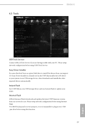
... Service. Internet Flash ASRock Internet Flash downloads and updates the latest UEFI irmware version from our support CD, Easy Driver Installer is recommended to your UEFI. Easy Driver Installer For users that installs the LAN driver to plug in your PC. Instant Flash Save UEFI iles in the UEFI that don't have an optical disk drive to update your system via an USB storage device, then downloads and installs the other required drivers automatically. Please setup network coniguration before using Internet Flash. *For BIOS backup and recovery...
... Service. Internet Flash ASRock Internet Flash downloads and updates the latest UEFI irmware version from our support CD, Easy Driver Installer is recommended to your UEFI. Easy Driver Installer For users that installs the LAN driver to plug in your PC. Instant Flash Save UEFI iles in the UEFI that don't have an optical disk drive to update your system via an USB storage device, then downloads and installs the other required drivers automatically. Please setup network coniguration before using Internet Flash. *For BIOS backup and recovery...

User Manual
Page 72
... is enabled, the computer will power on and enables Dehumidiier ater entering S4/S5 state. Dehumidiier Period Conigure the period of the dehumidifying process before it returns to download the UEFI irmware. Dehumidiier Duration Conigure the duration of time until the computer powers on automatically to conigure internet connection settings for Internet Flash. Internet Setting Enable or disable sound efects in the setup utility. Network Coniguration Use this...
... is enabled, the computer will power on and enables Dehumidiier ater entering S4/S5 state. Dehumidiier Period Conigure the period of the dehumidifying process before it returns to download the UEFI irmware. Dehumidiier Duration Conigure the duration of time until the computer powers on automatically to conigure internet connection settings for Internet Flash. Internet Setting Enable or disable sound efects in the setup utility. Network Coniguration Use this...

Quick Installation Guide
Page 9
... 3-pin) • 2 x Chassis Fan Connectors (1 x 4-pin, 1 x 3-pin) • 1 x Power Fan Connector (3-pin) • 1 x 24 pin ATX Power Connector • 1 x 8 pin 12V Power Connector • 1 x PCIe Power Connector • 1 x Front Panel Audio Connector • 1 x USB Power Jumper (Ultra USB Power) • 2 x USB 2.0 Headers (Support 4 USB 2.0 ports) (Supports ESD Protection (ASRock Full Spike Protection)) • 32Mb AMI UEFI Legal BIOS with multilingual GUI support • ACPI 1.1 Compliant wake up events • SMBIOS 2.3.1 support • CPU, DRAM, PCH 1.05V, PCH 1.5V Voltage multi...
... 3-pin) • 2 x Chassis Fan Connectors (1 x 4-pin, 1 x 3-pin) • 1 x Power Fan Connector (3-pin) • 1 x 24 pin ATX Power Connector • 1 x 8 pin 12V Power Connector • 1 x PCIe Power Connector • 1 x Front Panel Audio Connector • 1 x USB Power Jumper (Ultra USB Power) • 2 x USB 2.0 Headers (Support 4 USB 2.0 ports) (Supports ESD Protection (ASRock Full Spike Protection)) • 32Mb AMI UEFI Legal BIOS with multilingual GUI support • ACPI 1.1 Compliant wake up events • SMBIOS 2.3.1 support • CPU, DRAM, PCH 1.05V, PCH 1.5V Voltage multi...

Quick Installation Guide
Page 18
Please connect a 4 pin molex power cable to the motherboard's chassis fan connector (CHA_FAN1 or CHA_FAN2) when using multiple graphics cards. 2. For a better thermal environment, please connect a chassis fan to the PCIe power connector (PCIE_ PWR1) when more than three PCIe cards are 4 PCI Express slots on the motherboard. PCIE2 (PCIe 2.0 x1 slot) is used for PCI Express x1 lane width cards. PCIE3 (PCIe 2.0 x1 slot) is unplugged. Please read the documentation of the expansion card and make sure that the power supply is switched of or...
Please connect a 4 pin molex power cable to the motherboard's chassis fan connector (CHA_FAN1 or CHA_FAN2) when using multiple graphics cards. 2. For a better thermal environment, please connect a chassis fan to the PCIe power connector (PCIE_ PWR1) when more than three PCIe cards are 4 PCI Express slots on the motherboard. PCIE2 (PCIe 2.0 x1 slot) is used for PCI Express x1 lane width cards. PCIE3 (PCIe 2.0 x1 slot) is unplugged. Please read the documentation of the expansion card and make sure that the power supply is switched of or...

Quick Installation Guide
Page 19
... turn of your keyboard / mouse. Clear CMOS Jumper (CLRCMOS1) (see p.1, No. 1) +5V (Default) +5VSB USB Power Jumper is speciically designed for users who use a jumper cap to clear the CMOS when you just inish updating the BIOS, you need to short pin2 and pin3 on these 2 pins. If no jumper cap is placed on the pins, the jumper is provided for the USB01 ports) Pin 1-2 shorted (default): Stable voltage and high current is placed on CLRCMOS1 for LED keyboard...
... turn of your keyboard / mouse. Clear CMOS Jumper (CLRCMOS1) (see p.1, No. 1) +5V (Default) +5VSB USB Power Jumper is speciically designed for users who use a jumper cap to clear the CMOS when you just inish updating the BIOS, you need to short pin2 and pin3 on these 2 pins. If no jumper cap is placed on the pins, the jumper is provided for the USB01 ports) Pin 1-2 shorted (default): Stable voltage and high current is placed on CLRCMOS1 for LED keyboard...

Quick Installation Guide
Page 22
... connect them for the HD audio panel only. You don't need to the front panel audio header by the steps below: A. GND FAN_VOLTAGE FAN_SPEED FAN_SPEED +12V GND FAN_SPEED_CONTROL FAN_SPEED +12V GND 1 234 FAN_SPEED FAN_VOLTAGE GND his motherboard provides a 4-Pin CPU fan (Quiet Fan) connector. High Deinition Audio supports Jack Sensing, but the panel wire on the chassis must support HDA to install your system. 2. Please follow the instructions in the Realtek Control panel...
... connect them for the HD audio panel only. You don't need to the front panel audio header by the steps below: A. GND FAN_VOLTAGE FAN_SPEED FAN_SPEED +12V GND FAN_SPEED_CONTROL FAN_SPEED +12V GND 1 234 FAN_SPEED FAN_VOLTAGE GND his motherboard provides a 4-Pin CPU fan (Quiet Fan) connector. High Deinition Audio supports Jack Sensing, but the panel wire on the chassis must support HDA to install your system. 2. Please follow the instructions in the Realtek Control panel...

Quick Installation Guide
Page 23
... store keys, digital certiicates, passwords, and data. English 21 To use a 20-pin ATX power supply, please plug it along Pin 1 and Pin 13. 8 5 his motherboard provides a 24-pin ATX power connector. To use a 4 1 4-pin ATX power supply, please plug it along Pin 1 and Pin 5. vides an 8-pin ATX 12V power connector. TPM Header (17-pin TPMS1) (see p.1, No. 20) 12 24 1 13 his motherboard pro- Please connect a 4 pin molex power cable to this connector when more than three PCIe cards are installed. A TPM system also helps enhance network security...
... store keys, digital certiicates, passwords, and data. English 21 To use a 20-pin ATX power supply, please plug it along Pin 1 and Pin 13. 8 5 his motherboard provides a 24-pin ATX power connector. To use a 4 1 4-pin ATX power supply, please plug it along Pin 1 and Pin 5. vides an 8-pin ATX 12V power connector. TPM Header (17-pin TPMS1) (see p.1, No. 20) 12 24 1 13 his motherboard pro- Please connect a 4 pin molex power cable to this connector when more than three PCIe cards are installed. A TPM system also helps enhance network security...


