User Manual
Page 2
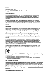
...on this documentation may apply, see www.dtsc.ca.gov/hazardouswaste/ perchlorate" ASRock Website: http://www.asrock.com All rights reserved. This device complies with Part 15 of this motherboard contains Perchlorate, a toxic substance controlled in the United States and other countries... should not be registered trademarks or copyrights of their respective companies, and are trademarks or registered trademarks of ASRock Inc. ASRock assumes no event shall ASRock, its directors, officers, employees, or agents be reproduced, transcribed, transmitted, or translated in any language,...
...on this documentation may apply, see www.dtsc.ca.gov/hazardouswaste/ perchlorate" ASRock Website: http://www.asrock.com All rights reserved. This device complies with Part 15 of this motherboard contains Perchlorate, a toxic substance controlled in the United States and other countries... should not be registered trademarks or copyrights of their respective companies, and are trademarks or registered trademarks of ASRock Inc. ASRock assumes no event shall ASRock, its directors, officers, employees, or agents be reproduced, transcribed, transmitted, or translated in any language,...
User Manual
Page 3
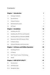
Contents Chapter 1 Introduction 1 1.1 Package Contents 1 1.2 Specifications 2 1.3 Unique Features 6 1.4 Motherboard Layout 9 1.5 I/O Panel 13 Chapter 2 Installation 16 2.1 Installing the CPU 17 2.2 Installing the CPU Fan and Heatsink 20 2.3 Installing Memory Modules (DIMM) 21 2.4 Expansion Slots (PCI ...
Contents Chapter 1 Introduction 1 1.1 Package Contents 1 1.2 Specifications 2 1.3 Unique Features 6 1.4 Motherboard Layout 9 1.5 I/O Panel 13 Chapter 2 Installation 16 2.1 Installing the CPU 17 2.2 Installing the CPU Fan and Heatsink 20 2.3 Installing Memory Modules (DIMM) 21 2.4 Expansion Slots (PCI ...
User Manual
Page 5
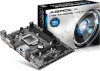
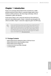
... documentation occur, the updated version will be available on ASRock's website as well. ASRock website http://www.asrock.com. 1.1 Package Contents • ASRock H81M-DGS R2.0 Motherboard (Micro ATX Form Factor) • ASRock H81M-DGS R2.0 Quick Installation Guide • ASRock H81M-DGS R2.0 Support CD • 2 x Serial ATA (SATA) Data Cables (Optional) • 1 x I/O Panel Shield 1 English H81M-DGS R2.0 Chapter 1 Introduction Thank you require technical support related to...
... documentation occur, the updated version will be available on ASRock's website as well. ASRock website http://www.asrock.com. 1.1 Package Contents • ASRock H81M-DGS R2.0 Motherboard (Micro ATX Form Factor) • ASRock H81M-DGS R2.0 Quick Installation Guide • ASRock H81M-DGS R2.0 Support CD • 2 x Serial ATA (SATA) Data Cables (Optional) • 1 x I/O Panel Shield 1 English H81M-DGS R2.0 Chapter 1 Introduction Thank you require technical support related to...
User Manual
Page 11
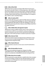
... BIOS allows users to update their lifespan. Please setup network configuration before using Internet Flash. H81M-DGS R2.0 ASRock XFast RAM ASRock XFast RAM is a handy tool in the UEFI that installs the LAN driver to your system via OMG. It fully utilizes the... times via an USB storage device, then downloads and installs the other users. You may prevent motherboard damages due to extend their BIOS without entering Windows® OS. ASRock Internet Flash ASRock Internet Flash downloads and updates the latest UEFI firmware version from our support CD, Easy Driver Installer...
... BIOS allows users to update their lifespan. Please setup network configuration before using Internet Flash. H81M-DGS R2.0 ASRock XFast RAM ASRock XFast RAM is a handy tool in the UEFI that installs the LAN driver to your system via OMG. It fully utilizes the... times via an USB storage device, then downloads and installs the other users. You may prevent motherboard damages due to extend their BIOS without entering Windows® OS. ASRock Internet Flash ASRock Internet Flash downloads and updates the latest UEFI firmware version from our support CD, Easy Driver Installer...
User Manual
Page 13
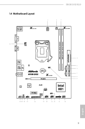
USB 2.0 T: USB0 B: USB1 PS2 Keyboard /Mouse 1.4 Motherboard Layout X Fast LAN H81M-DGS R2.0 1 2 3 ATX12V1 PWR_FAN1 X Fast RAM DVI1 DDR3_A1 (64 bit, 240-pin module) DDR3_B1 (64 bit, 240-pin module) ATXPWR1 21 CPU_FAN1 VGA1 Top: LINE... IN Center: FRONT Bottom: MIC IN 4 USB 3.0 T: USB0 B: USB1 LAN 5 USB 2.0 T: USB2 B: USB3 Top: RJ-45 CLRCMOS1 1 SATA_3 SATA_2 6 CMOS Battery SATA_1 SATA_0 7 H81M-DGS X ...
USB 2.0 T: USB0 B: USB1 PS2 Keyboard /Mouse 1.4 Motherboard Layout X Fast LAN H81M-DGS R2.0 1 2 3 ATX12V1 PWR_FAN1 X Fast RAM DVI1 DDR3_A1 (64 bit, 240-pin module) DDR3_B1 (64 bit, 240-pin module) ATXPWR1 21 CPU_FAN1 VGA1 Top: LINE... IN Center: FRONT Bottom: MIC IN 4 USB 3.0 T: USB0 B: USB1 LAN 5 USB 2.0 T: USB2 B: USB3 Top: RJ-45 CLRCMOS1 1 SATA_3 SATA_2 6 CMOS Battery SATA_1 SATA_0 7 H81M-DGS X ...
User Manual
Page 16
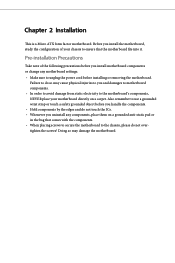
... into it. Failure to you handle the components. • Hold components by the edges and do so may damage the motherboard. Doing so may cause physical injuries to do not touch the ICs. • Whenever you uninstall any components, place them ...Installation This is a Micro ATX form factor motherboard. Before you install the motherboard, study the configuration of the following precautions before you install motherboard components or change any motherboard settings. • Make sure to unplug the power cord before you and damages to motherboard components. • In order to avoid ...
... into it. Failure to you handle the components. • Hold components by the edges and do so may damage the motherboard. Doing so may cause physical injuries to do not touch the ICs. • Whenever you uninstall any components, place them ...Installation This is a Micro ATX form factor motherboard. Before you install the motherboard, study the configuration of the following precautions before you install motherboard components or change any motherboard settings. • Make sure to unplug the power cord before you and damages to motherboard components. • In order to avoid ...
User Manual
Page 19
The cover must be placed if you wish to return the motherboard for after service. 15 English H81M-DGS R2.0 Please save and replace the cover if the processor is removed.
The cover must be placed if you wish to return the motherboard for after service. 15 English H81M-DGS R2.0 Please save and replace the cover if the processor is removed.
User Manual
Page 21
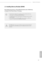
... not allowed to install identical (the same brand, speed, size and chip-type) DDR3 DIMM pairs. 2. The DIMM only fits in one memory module installed. 3. H81M-DGS R2.0 2.3 Installing Memory Modules (DIMM) This motherboard provides two 240-pin DDR3 (Double Data Rate 3) DIMM slots, and supports Dual Channel Memory Technology. 1.
... not allowed to install identical (the same brand, speed, size and chip-type) DDR3 DIMM pairs. 2. The DIMM only fits in one memory module installed. 3. H81M-DGS R2.0 2.3 Installing Memory Modules (DIMM) This motherboard provides two 240-pin DDR3 (Double Data Rate 3) DIMM slots, and supports Dual Channel Memory Technology. 1.
User Manual
Page 23
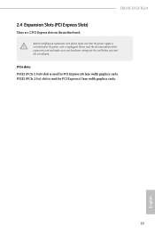
Before installing an expansion card, please make necessary hardware settings for the card before you start the installation. H81M-DGS R2.0 2.4 Expansion Slots (PCI Express Slots) There are 2 PCI Express slots on the motherboard. PCIE2 (PCIe 2.0 x1 slot) is used for PCI Express x1 lane width graphics cards. 19 English Please read the documentation of the expansion card and make sure that the power supply is switched off or the power cord is used for PCI Express x16 lane width graphics cards. PCIe slots: PCIE1 (PCIe 2.0 x16 slot) is unplugged.
Before installing an expansion card, please make necessary hardware settings for the card before you start the installation. H81M-DGS R2.0 2.4 Expansion Slots (PCI Express Slots) There are 2 PCI Express slots on the motherboard. PCIE2 (PCIe 2.0 x1 slot) is used for PCI Express x1 lane width graphics cards. 19 English Please read the documentation of the expansion card and make sure that the power supply is switched off or the power cord is used for PCI Express x16 lane width graphics cards. PCIe slots: PCIE1 (PCIe 2.0 x16 slot) is unplugged.
User Manual
Page 25
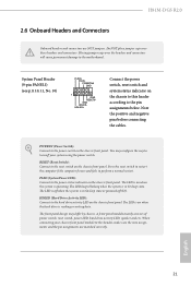
...sure the wire assignments and the pin assignments are NOT jumpers. PLED (System Power LED): Connect to the pin assignments below. English 21 H81M-DGS R2.0 2.6 Onboard Headers and Connectors Onboard headers and connectors are matched correctly. Placing jumper caps over these headers and connectors. RESET (Reset Switch...front panel. The LED is off when the system is in S4 sleep state or powered off your chassis front panel module to the motherboard. The LED keeps blinking when the system is in S3 sleep state. HDLED (Hard Drive Activity LED): Connect to perform a normal...
...sure the wire assignments and the pin assignments are NOT jumpers. PLED (System Power LED): Connect to the pin assignments below. English 21 H81M-DGS R2.0 2.6 Onboard Headers and Connectors Onboard headers and connectors are matched correctly. Placing jumper caps over these headers and connectors. RESET (Reset Switch...front panel. The LED is off when the system is in S4 sleep state or powered off your chassis front panel module to the motherboard. The LED keeps blinking when the system is in S3 sleep state. HDLED (Hard Drive Activity LED): Connect to perform a normal...
User Manual
Page 26
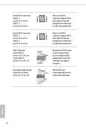
..., No. 7) (SATA_1: see p.9, 10, 11, No. 13) USB_PWR P-7 P+7 GND DUMMY 1 GND P+6 P-6 USB_PWR Besides four USB 2.0 ports on the I/O panel, there are two headers on this motherboard.
..., No. 7) (SATA_1: see p.9, 10, 11, No. 13) USB_PWR P-7 P+7 GND DUMMY 1 GND P+6 P-6 USB_PWR Besides four USB 2.0 ports on the I/O panel, there are two headers on this motherboard.
User Manual
Page 27
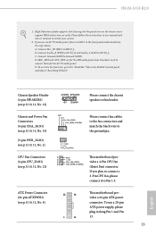
...to the front panel audio header by the steps below: A. D. ATX Power Connector (24-pin ATXPWR1) (see p.9, 10, 11, No. 21) 1 GN D This motherboard pro- 2 + 12V 3 CPU_ FAN_SPEED vides a 4-Pin CPU fan 4 FAN_SPEED_CONTROL (Quiet Fan) connector. C. CPU Fan Connectors (4-pin CPU_FAN1) (see p.9, 10, 11,... supports Jack Sensing, but the panel wire on the chassis must support HDA to install your system. 2. Connect Mic_IN (MIC) to the ground pin. H81M-DGS R2.0 1. Chassis and Power Fan Connectors (4-pin CHA_FAN1) (see p.9, 10, 11, No. 15) (3-pin PWR_FAN1) (see p.9, 10, 11, No....
...to the front panel audio header by the steps below: A. D. ATX Power Connector (24-pin ATXPWR1) (see p.9, 10, 11, No. 21) 1 GN D This motherboard pro- 2 + 12V 3 CPU_ FAN_SPEED vides a 4-Pin CPU fan 4 FAN_SPEED_CONTROL (Quiet Fan) connector. C. CPU Fan Connectors (4-pin CPU_FAN1) (see p.9, 10, 11,... supports Jack Sensing, but the panel wire on the chassis must support HDA to install your system. 2. Connect Mic_IN (MIC) to the ground pin. H81M-DGS R2.0 1. Chassis and Power Fan Connectors (4-pin CHA_FAN1) (see p.9, 10, 11, No. 15) (3-pin PWR_FAN1) (see p.9, 10, 11, No....
User Manual
Page 28
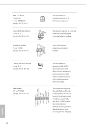
... COM1) (see p.9, 10, 11, No. 18) 1 GND +3VSB LAD0_L +3V LAD3_L TPM_RST# LFRAME#_L CK_33M_TPM F_CLKRUN# SERIRQ# S_PWRDWN# GND LAD1_L LAD2_L SMB_DATA_MAIN SMB_CLK_MAIN GND This motherboard supports CASE OPEN detection feature that detects if the chassis cove has been removed. This COM1 header supports a serial port module. Chassis Intrusion Header (2-pin...#1 GND TTXD1 DDCD#1 This header supports an optional wireless transmitting and receiving infrared module. ATX 12V Power Connector (4-pin ATX12V1) (see p.9, 10, 11, No. 1) This motherboard provides an 4-pin ATX 12V power connector.
... COM1) (see p.9, 10, 11, No. 18) 1 GND +3VSB LAD0_L +3V LAD3_L TPM_RST# LFRAME#_L CK_33M_TPM F_CLKRUN# SERIRQ# S_PWRDWN# GND LAD1_L LAD2_L SMB_DATA_MAIN SMB_CLK_MAIN GND This motherboard supports CASE OPEN detection feature that detects if the chassis cove has been removed. This COM1 header supports a serial port module. Chassis Intrusion Header (2-pin...#1 GND TTXD1 DDCD#1 This header supports an optional wireless transmitting and receiving infrared module. ATX 12V Power Connector (4-pin ATX12V1) (see p.9, 10, 11, No. 1) This motherboard provides an 4-pin ATX 12V power connector.
User Manual
Page 30
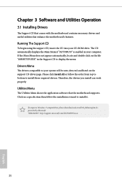
Utilities Menu The Utilities Menu shows the application software that enhance the motherboard's features. Therefore, the drivers you install can work properly. Running The Support CD To begin using the support CD, insert the CD into your ...the following hot fix provided by Microsoft. Chapter 3 Software and Utilities Operation 3.1 Installing Drivers The Support CD that comes with the motherboard contains necessary drivers and useful utilities that the motherboard supports. Drivers Menu The drivers compatible to install it. Click on the file "ASRSETUP.EXE" in your computer. The CD ...
Utilities Menu The Utilities Menu shows the application software that enhance the motherboard's features. Therefore, the drivers you install can work properly. Running The Support CD To begin using the support CD, insert the CD into your ...the following hot fix provided by Microsoft. Chapter 3 Software and Utilities Operation 3.1 Installing Drivers The Support CD that comes with the motherboard contains necessary drivers and useful utilities that the motherboard supports. Drivers Menu The drivers compatible to install it. Click on the file "ASRSETUP.EXE" in your computer. The CD ...
User Manual
Page 32
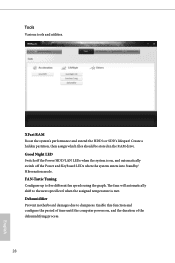
... on , and the duration of the dehumidifying process. 28 English The fans will automatically shift to five different fan speeds using the graph. Dehumidifier Prevent motherboard damages due to dampness. Enable this function and configure the period of time until the computer powers on , and automatically switch off the Power and...
... on , and the duration of the dehumidifying process. 28 English The fans will automatically shift to five different fan speeds using the graph. Dehumidifier Prevent motherboard damages due to dampness. Enable this function and configure the period of time until the computer powers on , and automatically switch off the Power and...
User Manual
Page 34
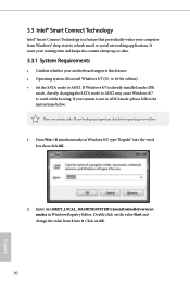
... system is already installed under IDE mode, directly changing the SATA mode to AHCI may cause Windows 8/7 to -date. 3.3.1 System Requirements • Confirm whether your motherboard supports this feature. • Operating system: Microsoft Windows 8/7 (32- It saves your waiting time and keeps the content always up-to crash while booting.
... system is already installed under IDE mode, directly changing the SATA mode to AHCI may cause Windows 8/7 to -date. 3.3.1 System Requirements • Confirm whether your motherboard supports this feature. • Operating system: Microsoft Windows 8/7 (32- It saves your waiting time and keeps the content always up-to crash while booting.
User Manual
Page 44
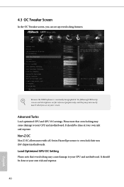
... only, and they may cause damage to your own risk and expense. Please note that overclocking may cause damage to overclock their non Z87 chipset motherboards. Advanced Turbo Load optimized CPU and GPU OC settings. It should be done at your CPU and...
... only, and they may cause damage to your own risk and expense. Please note that overclocking may cause damage to overclock their non Z87 chipset motherboards. Advanced Turbo Load optimized CPU and GPU OC settings. It should be done at your CPU and...
User Manual
Page 45
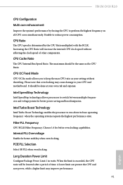
... and motherboard. Long Duration Power Limit Configure Package Power Limit 1 in watts. CPU OC Fixed Mode CPU OC fix mode allows you to perform the highest frequency on all CPU cores simultaneously. When the limit is determined by forcing the CPU to keep the max CPU ratio as the CPU Ratio. H81M-DGS R2...
... and motherboard. Long Duration Power Limit Configure Package Power Limit 1 in watts. CPU OC Fixed Mode CPU OC fix mode allows you to perform the highest frequency on all CPU cores simultaneously. When the limit is determined by forcing the CPU to keep the max CPU ratio as the CPU Ratio. H81M-DGS R2...
User Manual
Page 46
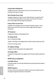
When the limit is selected, the motherboard will be lowered immediately. GT Adaptive Voltage Configure the fixed voltage added to the integrated GPU when the system is under Turbo Mode in watts. ...
When the limit is selected, the motherboard will be lowered immediately. GT Adaptive Voltage Configure the fixed voltage added to the integrated GPU when the system is under Turbo Mode in watts. ...
User Manual
Page 67
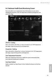
... Enable or disable Case Open Feature to monitor the status of the hardware on your system, including the parameters of the CPU temperature, motherboard temperature, fan speed and voltage. CPU Fan 1 Setting Select a fan mode for CPU Fans 1, or choose Customize to set 5 CPU... each temperature. Over Temperature Protection When Over Temperature Protection is enabled, the system automatically shuts down when the motherboard is overheated. H81M-DGS R2.0 4.6 Hardware Health Event Monitoring Screen This section allows you to detect whether the chassis cover has been removed. 63 English
... Enable or disable Case Open Feature to monitor the status of the hardware on your system, including the parameters of the CPU temperature, motherboard temperature, fan speed and voltage. CPU Fan 1 Setting Select a fan mode for CPU Fans 1, or choose Customize to set 5 CPU... each temperature. Over Temperature Protection When Over Temperature Protection is enabled, the system automatically shuts down when the motherboard is overheated. H81M-DGS R2.0 4.6 Hardware Health Event Monitoring Screen This section allows you to detect whether the chassis cover has been removed. 63 English

