User Manual
Page 3
... Specifications 2 1.3 Unique Features 6 1.4 Motherboard Layout 9 1.5 I/O Panel 13 Chapter 2 Installation 16 2.1 Installing the CPU 17 2.2 Installing the CPU Fan and Heatsink 20 2.3 Installing Memory Modules (DIMM) 21 2.4 Expansion Slots (PCI Express Slots) 23 2.5 Jumpers Setup 24 2.6 Onboard Headers and Connectors 25 Chapter 3 Software and Utilities Operation 30 3.1 Installing Drivers 30 3.2 A-Tuning 31 3.3 Intel® Smart Connect Technology 34 3.4 Start8 38 Chapter 4 UEFI SETUP UTILITY 41 4.1 Introduction 41 4.1.1 UEFI Menu Bar 41 4.1.2 Navigation Keys...
... Specifications 2 1.3 Unique Features 6 1.4 Motherboard Layout 9 1.5 I/O Panel 13 Chapter 2 Installation 16 2.1 Installing the CPU 17 2.2 Installing the CPU Fan and Heatsink 20 2.3 Installing Memory Modules (DIMM) 21 2.4 Expansion Slots (PCI Express Slots) 23 2.5 Jumpers Setup 24 2.6 Onboard Headers and Connectors 25 Chapter 3 Software and Utilities Operation 30 3.1 Installing Drivers 30 3.2 A-Tuning 31 3.3 Intel® Smart Connect Technology 34 3.4 Start8 38 Chapter 4 UEFI SETUP UTILITY 41 4.1 Introduction 41 4.1.1 UEFI Menu Bar 41 4.1.2 Navigation Keys...
User Manual
Page 5
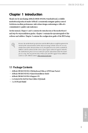
... of the software and utilities. You may find the latest VGA cards and CPU support list on ASRock's website without notice. ASRock website http://www.asrock.com. 1.1 Package Contents • ASRock H81M-DGS R2.0 Motherboard (Micro ATX Form Factor) • ASRock H81M-DGS R2.0 Quick Installation Guide • ASRock H81M-DGS R2.0 Support CD • 2 x Serial ATA (SATA) Data Cables (Optional) • 1 x I/O Panel Shield 1 English Chapter 3 contains the operation guide of the BIOS setup. In this motherboard, please visit our website for purchasing ASRock H81M-DGS R2.0 motherboard...
... of the software and utilities. You may find the latest VGA cards and CPU support list on ASRock's website without notice. ASRock website http://www.asrock.com. 1.1 Package Contents • ASRock H81M-DGS R2.0 Motherboard (Micro ATX Form Factor) • ASRock H81M-DGS R2.0 Quick Installation Guide • ASRock H81M-DGS R2.0 Support CD • 2 x Serial ATA (SATA) Data Cables (Optional) • 1 x I/O Panel Shield 1 English Chapter 3 contains the operation guide of the BIOS setup. In this motherboard, please visit our website for purchasing ASRock H81M-DGS R2.0 motherboard...
User Manual
Page 8
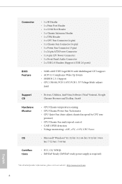
...8226; 1 x Power Fan Connector (3-pin) • 1 x 24 pin ATX Power Connector • 1 x 4 pin 12V Power Connector • 1 x Front Panel Audio Connector • 2 x USB 2.0 Headers (Support 4 USB 2.0 ports) BIOS Feature • 32Mb AMI UEFI Legal BIOS with Multilingual GUI support • ACPI 1.1 Compliance Wake Up Events • SMBIOS 2.3.1 Support • CPU, DRAM, PCH 1.05V, PCH 1.5V Voltage Multi-adjust- perature) • CPU/Chassis Fan multi-speed control • CASE OPEN detection • Voltage monitoring: +12V, +5V, +3.3V, CPU Vcore OS • Microsoft® Windows®...
...8226; 1 x Power Fan Connector (3-pin) • 1 x 24 pin ATX Power Connector • 1 x 4 pin 12V Power Connector • 1 x Front Panel Audio Connector • 2 x USB 2.0 Headers (Support 4 USB 2.0 ports) BIOS Feature • 32Mb AMI UEFI Legal BIOS with Multilingual GUI support • ACPI 1.1 Compliance Wake Up Events • SMBIOS 2.3.1 Support • CPU, DRAM, PCH 1.05V, PCH 1.5V Voltage Multi-adjust- perature) • CPU/Chassis Fan multi-speed control • CASE OPEN detection • Voltage monitoring: +12V, +5V, +3.3V, CPU Vcore OS • Microsoft® Windows®...
User Manual
Page 10
... latency in Flash ROM. ASRock XFast LAN ASRock XFast LAN provides faster internet access, which data streams you are currently transferring. 6 English Please be noted that the USB flash drive or hard drive must use FAT32/16/12 file system. ASRock XFast USB ASRock XFast USB can watch Youtube HD videos and download simultaneously. Traffic Shaping: You can boost the performance of your PC enters into Suspend to update the system BIOS in...
... latency in Flash ROM. ASRock XFast LAN ASRock XFast LAN provides faster internet access, which data streams you are currently transferring. 6 English Please be noted that the USB flash drive or hard drive must use FAT32/16/12 file system. ASRock XFast USB ASRock XFast USB can watch Youtube HD videos and download simultaneously. Traffic Shaping: You can boost the performance of your PC enters into Suspend to update the system BIOS in...
User Manual
Page 11
... utilizes the memory space that it also boosts the speed of internet access granted to other required drivers automatically. 7 English H81M-DGS R2.0 ASRock XFast RAM ASRock XFast RAM is included in order to extend their BIOS without fear of your SSDs or HDDs in A-Tuning. And it reduces the frequency of your system via OMG. Please note that installs the LAN driver to your USB disk. ASRock Internet Flash ASRock Internet Flash downloads and updates...
... utilizes the memory space that it also boosts the speed of internet access granted to other required drivers automatically. 7 English H81M-DGS R2.0 ASRock XFast RAM ASRock XFast RAM is included in order to extend their BIOS without fear of your SSDs or HDDs in A-Tuning. And it reduces the frequency of your system via OMG. Please note that installs the LAN driver to your USB disk. ASRock Internet Flash ASRock Internet Flash downloads and updates...
User Manual
Page 13
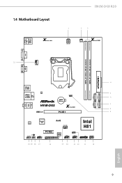
USB 2.0 T: USB0 B: USB1 PS2 Keyboard /Mouse 1.4 Motherboard Layout X Fast LAN H81M-DGS R2.0 1 2 3 ATX12V1 PWR_FAN1 X Fast RAM DVI1 DDR3_A1 (64 bit, 240-pin module) DDR3_B1 (64 bit, 240-pin module) ATXPWR1 21 CPU_FAN1 VGA1 Top: LINE IN Center: FRONT Bottom: MIC IN 4 USB 3.0 T: USB0 B: USB1 LAN 5 USB 2.0 T: USB2 B: USB3 Top: RJ-45 CLRCMOS1 1 SATA_3 SATA_2 6 CMOS Battery SATA_1 SATA_0 7 H81M-DGS X Fast USB 8 USB 3.0 PCIE1 9 Audio CODEC Super I/O RoHS CHA_FAN1 Intel H81 HD_AUDIO1 CI1...
USB 2.0 T: USB0 B: USB1 PS2 Keyboard /Mouse 1.4 Motherboard Layout X Fast LAN H81M-DGS R2.0 1 2 3 ATX12V1 PWR_FAN1 X Fast RAM DVI1 DDR3_A1 (64 bit, 240-pin module) DDR3_B1 (64 bit, 240-pin module) ATXPWR1 21 CPU_FAN1 VGA1 Top: LINE IN Center: FRONT Bottom: MIC IN 4 USB 3.0 T: USB0 B: USB1 LAN 5 USB 2.0 T: USB2 B: USB3 Top: RJ-45 CLRCMOS1 1 SATA_3 SATA_2 6 CMOS Battery SATA_1 SATA_0 7 H81M-DGS X Fast USB 8 USB 3.0 PCIE1 9 Audio CODEC Super I/O RoHS CHA_FAN1 Intel H81 HD_AUDIO1 CI1...
User Manual
Page 14
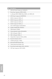
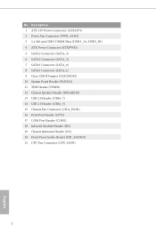
...2 Power Fan Connector (PWR_FAN1) 3 2 x 240-pin DDR3 DIMM Slots (DDR3_A1, DDR3_B1) 4 ATX Power Connector (ATXPWR1) 5 SATA2 Connector (SATA_3) 6 SATA2 Connector (SATA_2) 7 SATA3 Connector (SATA_0) 8 SATA3 Connector (SATA_1) 9 Clear CMOS Jumper (CLRCMOS1) 10 System Panel Header (PANEL1) 11 TPM Header (TPMS1) 12 Chassis Speaker Header (SPEAKER1) 13 USB 2.0 Header (USB6_7) 14 USB 2.0 Header (USB4_5) 15 Chassis Fan Connector (CHA_FAN1) 16 Print Port Header (LPT1) 17 COM Port Header (COM1) 18 Infrared Module Header (IR1) 19 Chassis Intrusion Header (CI1) 20 Front Panel Audio Header (HD_AUDIO1) 21 CPU...
...2 Power Fan Connector (PWR_FAN1) 3 2 x 240-pin DDR3 DIMM Slots (DDR3_A1, DDR3_B1) 4 ATX Power Connector (ATXPWR1) 5 SATA2 Connector (SATA_3) 6 SATA2 Connector (SATA_2) 7 SATA3 Connector (SATA_0) 8 SATA3 Connector (SATA_1) 9 Clear CMOS Jumper (CLRCMOS1) 10 System Panel Header (PANEL1) 11 TPM Header (TPMS1) 12 Chassis Speaker Header (SPEAKER1) 13 USB 2.0 Header (USB6_7) 14 USB 2.0 Header (USB4_5) 15 Chassis Fan Connector (CHA_FAN1) 16 Print Port Header (LPT1) 17 COM Port Header (COM1) 18 Infrared Module Header (IR1) 19 Chassis Intrusion Header (CI1) 20 Front Panel Audio Header (HD_AUDIO1) 21 CPU...
User Manual
Page 23
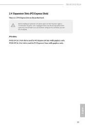
PCIE2 (PCIe 2.0 x1 slot) is used for the card before you start the installation. Please read the documentation of the expansion card and make sure that the power supply is switched off or the power cord is unplugged. PCIe slots: PCIE1 (PCIe 2.0 x16 slot) is used for PCI Express x16 lane width graphics cards. Before installing an expansion card, please make necessary hardware settings for PCI Express x1 lane width graphics cards. 19 English H81M-DGS R2.0 2.4 Expansion Slots (PCI Express Slots) There are 2 PCI Express slots on the motherboard.
PCIE2 (PCIe 2.0 x1 slot) is used for the card before you start the installation. Please read the documentation of the expansion card and make sure that the power supply is switched off or the power cord is unplugged. PCIe slots: PCIE1 (PCIe 2.0 x16 slot) is used for PCI Express x16 lane width graphics cards. Before installing an expansion card, please make necessary hardware settings for PCI Express x1 lane width graphics cards. 19 English H81M-DGS R2.0 2.4 Expansion Slots (PCI Express Slots) There are 2 PCI Express slots on the motherboard.
User Manual
Page 24
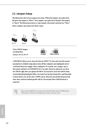
... on the pins, the jumper is "Short". Please adjust the BIOS option "Clear Status" to default setup, please turn off the computer and unplug the power cord from the power supply. Clear CMOS Jumper (CLRCMOS1) (see p.9, 10, 11, No. 9) Default Clear CMOS CLRCMOS1 allows you do not clear the CMOS right after you clear the CMOS, the case open may be cleared only if the CMOS battery is removed. English 20 However, please do the clear-CMOS action. After...
... on the pins, the jumper is "Short". Please adjust the BIOS option "Clear Status" to default setup, please turn off the computer and unplug the power cord from the power supply. Clear CMOS Jumper (CLRCMOS1) (see p.9, 10, 11, No. 9) Default Clear CMOS CLRCMOS1 allows you do not clear the CMOS right after you clear the CMOS, the case open may be cleared only if the CMOS battery is removed. English 20 However, please do the clear-CMOS action. After...
User Manual
Page 25
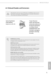
... the chassis front panel. A front panel module mainly consists of power switch, reset switch, power LED, hard drive activity LED, speaker and etc. English 21 H81M-DGS R2.0 2.6 Onboard Headers and Connectors Onboard headers and connectors are matched correctly. PWRBTN (Power Switch): Connect to the pin assignments below. The LED is on when the system is reading or writing data. HDLED (Hard Drive Activity LED): Connect to the hard drive activity LED on the chassis to this header, make sure the wire assignments and the pin assignments are NOT jumpers...
... the chassis front panel. A front panel module mainly consists of power switch, reset switch, power LED, hard drive activity LED, speaker and etc. English 21 H81M-DGS R2.0 2.6 Onboard Headers and Connectors Onboard headers and connectors are matched correctly. PWRBTN (Power Switch): Connect to the pin assignments below. The LED is on when the system is reading or writing data. HDLED (Hard Drive Activity LED): Connect to the hard drive activity LED on the chassis to this header, make sure the wire assignments and the pin assignments are NOT jumpers...
User Manual
Page 30
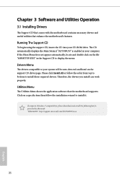
... computer. Drivers Menu The drivers compatible to display the menu. To improve Windows 7 compatibility, please download and install the following hot fix provided by Microsoft. Therefore, the drivers you install can work properly. "KB2720599": http://support.microsoft.com/kb/2720599/en-us 26 English Utilities Menu The Utilities Menu shows the application software that enhance the motherboard's features. If the Main Menu does not appear automatically, locate and double click on a specific item then...
... computer. Drivers Menu The drivers compatible to display the menu. To improve Windows 7 compatibility, please download and install the following hot fix provided by Microsoft. Therefore, the drivers you install can work properly. "KB2720599": http://support.microsoft.com/kb/2720599/en-us 26 English Utilities Menu The Utilities Menu shows the application software that enhance the motherboard's features. If the Main Menu does not appear automatically, locate and double click on a specific item then...
User Manual
Page 34
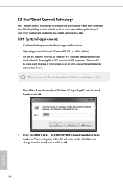
... refresh email or social networking applications. Press Win + R simultaneously in Windows 8/7, type "Regedit" into HKEY_LOCAL_MACHINE\SYSTEM\CurrentControlSet\services\ msahci in AHCI mode, please follow the instructions below. If your system is already installed under IDE mode, directly changing the SATA mode to AHCI may cause Windows 8/7 to avoid loss. 1. Please backup any important data before operating to crash while booting. It saves your motherboard supports this feature. • Operating...
... refresh email or social networking applications. Press Win + R simultaneously in Windows 8/7, type "Regedit" into HKEY_LOCAL_MACHINE\SYSTEM\CurrentControlSet\services\ msahci in AHCI mode, please follow the instructions below. If your system is already installed under IDE mode, directly changing the SATA mode to AHCI may cause Windows 8/7 to avoid loss. 1. Please backup any important data before operating to crash while booting. It saves your motherboard supports this feature. • Operating...
User Manual
Page 41
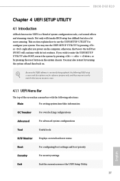
...4.1.1 UEFI Menu Bar The top of system configuration tools, cool sound effects and stunning visuals. H81M-DGS R2.0 Chapter 4 UEFI SETUP UTILITY 4.1 Introduction ASRock Interactive UEFI is constantly being updated, the following selections: Main For setting system time/date information OC Tweaker For overclocking configurations Advanced For advanced system configurations Tool Useful tools H/W Monitor Displays current hardware status Boot For configuring boot settings and boot priority Security For security settings Exit Exit the current screen or the UEFI Setup Utility...
...4.1.1 UEFI Menu Bar The top of system configuration tools, cool sound effects and stunning visuals. H81M-DGS R2.0 Chapter 4 UEFI SETUP UTILITY 4.1 Introduction ASRock Interactive UEFI is constantly being updated, the following selections: Main For setting system time/date information OC Tweaker For overclocking configurations Advanced For advanced system configurations Tool Useful tools H/W Monitor Displays current hardware status Boot For configuring boot settings and boot priority Security For security settings Exit Exit the current screen or the UEFI Setup Utility...
User Manual
Page 56
... start to enable onboard HD audio and automatically disable it when a sound card is selected, the power will also automatically switch off when the power recovers. Onboard LAN Enable or disable the onboard network interface controller. Restore on . Render Standby Power down . Set to Auto to boot up when the power recovers. If [Power Off] is installed. Front Panel Enable/disable front panel HD audio. Onboard HD Audio Enable/disable onboard HD audio. It will remain off the Power and Keyboard LEDs when the system enters into Standby/Hibernation mode...
... start to enable onboard HD audio and automatically disable it when a sound card is selected, the power will also automatically switch off when the power recovers. Onboard LAN Enable or disable the onboard network interface controller. Restore on . Render Standby Power down . Set to Auto to boot up when the power recovers. If [Power Off] is installed. Front Panel Enable/disable front panel HD audio. Onboard HD Audio Enable/disable onboard HD audio. It will remain off the Power and Keyboard LEDs when the system enters into Standby/Hibernation mode...
User Manual
Page 64
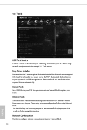
... recovery purpose, it is a handy tool in your system via an USB storage device, then downloads and installs the other required drivers automatically. Internet Flash ASRock Internet Flash downloads and updates the latest UEFI firmware version from our support CD, Easy Driver Installer is recommended to plug in the UEFI that installs the LAN driver to configure internet connection settings for you are having trouble with your UEFI. 4.5 Tools UEFI Tech Service Contact ASRock Tech Service if you . Network Configuration Use this function. Easy Driver Installer For users...
... recovery purpose, it is a handy tool in your system via an USB storage device, then downloads and installs the other required drivers automatically. Internet Flash ASRock Internet Flash downloads and updates the latest UEFI firmware version from our support CD, Easy Driver Installer is recommended to plug in the UEFI that installs the LAN driver to configure internet connection settings for you are having trouble with your UEFI. 4.5 Tools UEFI Tech Service Contact ASRock Tech Service if you . Network Configuration Use this function. Easy Driver Installer For users...
Quick Installation Guide
Page 3
...2 Power Fan Connector (PWR_FAN1) 3 2 x 240-pin DDR3 DIMM Slots (DDR3_A1, DDR3_B1) 4 ATX Power Connector (ATXPWR1) 5 SATA2 Connector (SATA_3) 6 SATA2 Connector (SATA_2) 7 SATA3 Connector (SATA_0) 8 SATA3 Connector (SATA_1) 9 Clear CMOS Jumper (CLRCMOS1) 10 System Panel Header (PANEL1) 11 TPM Header (TPMS1) 12 Chassis Speaker Header (SPEAKER1) 13 USB 2.0 Header (USB6_7) 14 USB 2.0 Header (USB4_5) 15 Chassis Fan Connector (CHA_FAN1) 16 Print Port Header (LPT1) 17 COM Port Header (COM1) 18 Infrared Module Header (IR1) 19 Chassis Intrusion Header (CI1) 20 Front Panel Audio Header (HD_AUDIO1) 21 CPU...
...2 Power Fan Connector (PWR_FAN1) 3 2 x 240-pin DDR3 DIMM Slots (DDR3_A1, DDR3_B1) 4 ATX Power Connector (ATXPWR1) 5 SATA2 Connector (SATA_3) 6 SATA2 Connector (SATA_2) 7 SATA3 Connector (SATA_0) 8 SATA3 Connector (SATA_1) 9 Clear CMOS Jumper (CLRCMOS1) 10 System Panel Header (PANEL1) 11 TPM Header (TPMS1) 12 Chassis Speaker Header (SPEAKER1) 13 USB 2.0 Header (USB6_7) 14 USB 2.0 Header (USB4_5) 15 Chassis Fan Connector (CHA_FAN1) 16 Print Port Header (LPT1) 17 COM Port Header (COM1) 18 Infrared Module Header (IR1) 19 Chassis Intrusion Header (CI1) 20 Front Panel Audio Header (HD_AUDIO1) 21 CPU...
Quick Installation Guide
Page 8
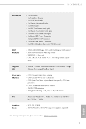
...://www.asrock.com 7 English H81M-DGS R2.0 Connector • 1 x IR Header • 1 x Print Port Header • 1 x COM Port Header • 1 x Chassis Intrusion Header • 1 x TPM Header • 1 x CPU Fan Connector (4-pin) • 1 x Chassis Fan Connector (4-pin) • 1 x Power Fan Connector (3-pin) • 1 x 24 pin ATX Power Connector • 1 x 4 pin 12V Power Connector • 1 x Front Panel Audio Connector • 2 x USB 2.0 Headers (Support 4 USB 2.0 ports) BIOS Feature • 32Mb AMI UEFI Legal BIOS with Multilingual GUI support • ACPI 1.1 Compliance Wake Up...
...://www.asrock.com 7 English H81M-DGS R2.0 Connector • 1 x IR Header • 1 x Print Port Header • 1 x COM Port Header • 1 x Chassis Intrusion Header • 1 x TPM Header • 1 x CPU Fan Connector (4-pin) • 1 x Chassis Fan Connector (4-pin) • 1 x Power Fan Connector (3-pin) • 1 x 24 pin ATX Power Connector • 1 x 4 pin 12V Power Connector • 1 x Front Panel Audio Connector • 2 x USB 2.0 Headers (Support 4 USB 2.0 ports) BIOS Feature • 32Mb AMI UEFI Legal BIOS with Multilingual GUI support • ACPI 1.1 Compliance Wake Up...
Quick Installation Guide
Page 10
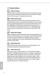
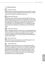
... H81M-DGS R2.0 1.3 Unique Features ASRock A-Tuning A-Tuning is a BIOS flash utility embedded in games. ASRock Instant Flash ASRock Instant Flash is ASRock's multi purpose software suite with a new interface, more new features and improved utilities, including XFast RAM, Dehumidifier, Good Night LED, FAN-Tastic Tuning, OC Tweaker and a whole lot more. ASRock APP Charger Simply by pressing or during POST to enter the BIOS setup menu to RAM (S3), hibernation mode (S4) or power off...
... H81M-DGS R2.0 1.3 Unique Features ASRock A-Tuning A-Tuning is a BIOS flash utility embedded in games. ASRock Instant Flash ASRock Instant Flash is ASRock's multi purpose software suite with a new interface, more new features and improved utilities, including XFast RAM, Dehumidifier, Good Night LED, FAN-Tastic Tuning, OC Tweaker and a whole lot more. ASRock APP Charger Simply by pressing or during POST to enter the BIOS setup menu to RAM (S3), hibernation mode (S4) or power off...
Quick Installation Guide
Page 11
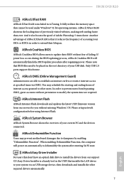
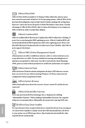
... internet access at specified times via an USB storage device, then downloads and installs the other users. ASRock Internet Flash ASRock Internet Flash downloads and updates the latest UEFI firmware version from our support CD, Easy Driver Installer is a handy tool in the UEFI that cannot be placed in the root directory of your system via OMG. ASRock XFast RAM ASRock XFast RAM is that BIOS files need to extend their BIOS without entering Windows® OS. If power loss...
... internet access at specified times via an USB storage device, then downloads and installs the other users. ASRock Internet Flash ASRock Internet Flash downloads and updates the latest UEFI firmware version from our support CD, Easy Driver Installer is a handy tool in the UEFI that cannot be placed in the root directory of your system via OMG. ASRock XFast RAM ASRock XFast RAM is that BIOS files need to extend their BIOS without entering Windows® OS. If power loss...
Quick Installation Guide
Page 12
... interface and more waiting! No more amusment. Just plug in the USB Key and let your user experience and behavior. ASRock Restart to enter the UEFI automatically when turning on . ASRock Restart to UEFI allows users to UEFI Windows® 8 brings the ultimate boot up to windows automatically! Configure up experience. H81M-DGS R2.0 ASRock Interactive UEFI ASRock Interactive UEFI is powered on the PC. By enabling Good Night LED in to five different fan speeds using the graph.
... interface and more waiting! No more amusment. Just plug in the USB Key and let your user experience and behavior. ASRock Restart to enter the UEFI automatically when turning on . ASRock Restart to UEFI allows users to UEFI Windows® 8 brings the ultimate boot up to windows automatically! Configure up experience. H81M-DGS R2.0 ASRock Interactive UEFI ASRock Interactive UEFI is powered on the PC. By enabling Good Night LED in to five different fan speeds using the graph.


