
User Manual
Page 12
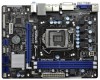
... RoHS Fast USB X Fast LAN X AT X P W R 1 22.6cm (8.9 in Taipei AUDIO CODEC Super I/O CLRCMOS1 1 CMOS 21 Battery 20 PCIE2 Intel 6 H61 32Mb BIOS 7 HD_AUDIO1 1 1 LPT1 USB8_9 1 SATA2_3 SATA2_1 SPEAKER1 1 CHA_FAN1 8 COM1 USB6_7 PLED PWRBTN 1 1 1 HDLED RESET PANEL1 SATA2_2 SATA2_0 ...19 18 17 16 15 14 13 12 11 10 9 1 1155-Pin CPU Socket 2 ATX 12V Power Connector (ATX12V1) 3 CPU Fan Connector (CPU_FAN1) 4 ATX Power Connector (ATXPWR1) 5 2 x 240-pin DDR3 DIMM Slots (...
... RoHS Fast USB X Fast LAN X AT X P W R 1 22.6cm (8.9 in Taipei AUDIO CODEC Super I/O CLRCMOS1 1 CMOS 21 Battery 20 PCIE2 Intel 6 H61 32Mb BIOS 7 HD_AUDIO1 1 1 LPT1 USB8_9 1 SATA2_3 SATA2_1 SPEAKER1 1 CHA_FAN1 8 COM1 USB6_7 PLED PWRBTN 1 1 1 HDLED RESET PANEL1 SATA2_2 SATA2_0 ...19 18 17 16 15 14 13 12 11 10 9 1 1155-Pin CPU Socket 2 ATX 12V Power Connector (ATX12V1) 3 CPU Fan Connector (CPU_FAN1) 4 ATX Power Connector (ATXPWR1) 5 2 x 240-pin DDR3 DIMM Slots (...
User Manual
Page 15
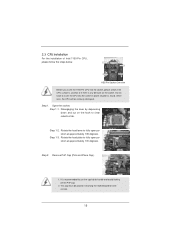
...fully open position at approximately 100 degrees. Open the socket: Step 1-1. Step 1-3. Step 2. This cap must be seriously damaged. Load Plate Load Lever Contact Array Socket Body 1155-Pin Socket Overview Before you insert the 1155-Pin CPU into the socket, please check if the CPU surface is unclean ...into the socket if above situation is recommended to use the cap tab to handle and avoid kicking off the PnP cap. 2. Rotate the load plate to fully open position at approximately 135 degrees. It is found. 2.3 CPU Installation For the installation of Intel 1155-Pin CPU,...
...fully open position at approximately 100 degrees. Open the socket: Step 1-1. Step 1-3. Step 2. This cap must be seriously damaged. Load Plate Load Lever Contact Array Socket Body 1155-Pin Socket Overview Before you insert the 1155-Pin CPU into the socket, please check if the CPU surface is unclean ...into the socket if above situation is recommended to use the cap tab to handle and avoid kicking off the PnP cap. 2. Rotate the load plate to fully open position at approximately 135 degrees. It is found. 2.3 CPU Installation For the installation of Intel 1155-Pin CPU,...
User Manual
Page 17
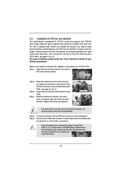
..., then press down the fasteners without rotating them clockwise, the heatsink cannot be noticed that supports Intel 1155-Pin CPU. Step 6. Please be secured on the socket surface. Then connect the CPU fan to improve heat dissipation. Apply thermal interface material onto center of... the heatsink for Socket LGA 1155/1156 CPU fan. 17 Place the heatsink onto the socket. Repeat with the motherboard throughholes. Apply Thermal Interface Material Step 2. Ensure that the CPU and...
..., then press down the fasteners without rotating them clockwise, the heatsink cannot be noticed that supports Intel 1155-Pin CPU. Step 6. Please be secured on the socket surface. Then connect the CPU fan to improve heat dissipation. Apply thermal interface material onto center of... the heatsink for Socket LGA 1155/1156 CPU fan. 17 Place the heatsink onto the socket. Repeat with the motherboard throughholes. Apply Thermal Interface Material Step 2. Ensure that the CPU and...

Quick Installation Guide
Page 2
... W R 1 22.6cm (8.9 in Taipei AUDIO CODEC Super I/O CLRCMOS1 1 CMOS 21 Battery 20 PCIE2 Intel 6 H61 32Mb BIOS 7 HD_AUDIO1 1 1 LPT1 USB8_9 1 SATA2_3 SATA2_1 SPEAKER1 1 CHA_FAN1 8 COM1 USB6_7 ...1 HDLED RESET PANEL1 SATA2_2 SATA2_0 19 18 17 16 15 14 13 12 11 10 9 1 1155-Pin CPU Socket 2 ATX 12V Power Connector (ATX12V1) 3 CPU Fan Connector (CPU_FAN1) 4 ATX Power Connector (ATXPWR1...) 22 PCI Express 3.0 x16 Slot (PCIE1, Blue) 23 Power Fan Connector (PWR_FAN1) 2 ASRock H71M-DGS Motherboard English D G S PWR_FAN1 LAN PHY 5 22 PCIE1 Designed in ) DDR3_B1 (64 bit...
... W R 1 22.6cm (8.9 in Taipei AUDIO CODEC Super I/O CLRCMOS1 1 CMOS 21 Battery 20 PCIE2 Intel 6 H61 32Mb BIOS 7 HD_AUDIO1 1 1 LPT1 USB8_9 1 SATA2_3 SATA2_1 SPEAKER1 1 CHA_FAN1 8 COM1 USB6_7 ...1 HDLED RESET PANEL1 SATA2_2 SATA2_0 19 18 17 16 15 14 13 12 11 10 9 1 1155-Pin CPU Socket 2 ATX 12V Power Connector (ATX12V1) 3 CPU Fan Connector (CPU_FAN1) 4 ATX Power Connector (ATXPWR1...) 22 PCI Express 3.0 x16 Slot (PCIE1, Blue) 23 Power Fan Connector (PWR_FAN1) 2 ASRock H71M-DGS Motherboard English D G S PWR_FAN1 LAN PHY 5 22 PCIE1 Designed in ) DDR3_B1 (64 bit...

Quick Installation Guide
Page 11
... is unclean or if there is found. Unplug the power cord from the wall socket before you uninstall any motherboard settings. 1. Load Plate Contact Array Load Lever Socket Body 1155-Pin Socket Overview Before you handle components. 3. Hold components by the edges and do so may...pad or in the bag that comes with the component. 5. 2. Installation Pre-installation Precautions Take note of Intel 1155-Pin CPU, please follow the steps below. English 11 ASRock H71M-DGS Motherboard Failure to do not touch the ICs. 4. Otherwise, the CPU will be seriously damaged. Whenever ...
... is unclean or if there is found. Unplug the power cord from the wall socket before you uninstall any motherboard settings. 1. Load Plate Contact Array Load Lever Socket Body 1155-Pin Socket Overview Before you handle components. 3. Hold components by the edges and do so may...pad or in the bag that comes with the component. 5. 2. Installation Pre-installation Precautions Take note of Intel 1155-Pin CPU, please follow the steps below. English 11 ASRock H71M-DGS Motherboard Failure to do not touch the ICs. 4. Otherwise, the CPU will be seriously damaged. Whenever ...


