
Intel Rapid Storage Guide
Page 12
Enable RAID in System BIOS Use the instructions included with your motherboard to enter the BIOS Setup program after the Power-On-Self-Test (POST) memory test begins. 2. Click F2 or Delete to enable RAID in the ...
Enable RAID in System BIOS Use the instructions included with your motherboard to enter the BIOS Setup program after the Power-On-Self-Test (POST) memory test begins. 2. Click F2 or Delete to enable RAID in the ...
User Manual
Page 2
...means, except duplication of documentation by the California Legislature. With respect to infringe. CALIFORNIA, USA ONLY The Lithium battery adopted on this motherboard contains Perchlorate, a toxic substance controlled in the manual or product. "Perchlorate Material-special handling may cause undesired operation. When you discard...or tness for loss of pro ts, loss of business, loss of data, interruption of business and the like), even if ASRock has been advised of the possibility of any defect or error in Perchlorate Best Management Practices (BMP) regulations passed by the ...
...means, except duplication of documentation by the California Legislature. With respect to infringe. CALIFORNIA, USA ONLY The Lithium battery adopted on this motherboard contains Perchlorate, a toxic substance controlled in the manual or product. "Perchlorate Material-special handling may cause undesired operation. When you discard...or tness for loss of pro ts, loss of business, loss of data, interruption of business and the like), even if ASRock has been advised of the possibility of any defect or error in Perchlorate Best Management Practices (BMP) regulations passed by the ...

User Manual
Page 3
Contents 1 Introduction 5 1.1 Package Contents 5 1.2 Speci cations 6 1.3 Motherboard Layout 12 1.4 I/O Panel 13 2 Installation 15 2.1 Screw Holes 15 2.2 Pre-installation Precautions 15 2.3 CPU Installation 16 2.4 Installation of Heatsink and CPU fan 18 2.5 Installation of ...
Contents 1 Introduction 5 1.1 Package Contents 5 1.2 Speci cations 6 1.3 Motherboard Layout 12 1.4 I/O Panel 13 2 Installation 15 2.1 Screw Holes 15 2.2 Pre-installation Precautions 15 2.3 CPU Installation 16 2.4 Installation of Heatsink and CPU fan 18 2.5 Installation of ...
User Manual
Page 5
... in , 24.4 cm x 21.8 cm) ASRock H67M Quick Installation Guide ASRock H67M Support CD 2 x Serial ATA (SATA) Data Cables (Optional) 1 x I/O Panel Shield 1 x 3D Red/Cyan Anaglyph Glasses (Optional) ASRock Reminds You... In this manual, chapter 1 and 2 contain introduction of this motherboard, please visit our website for purchasing ASRock H67M motherboard, a reliable motherboard produced under ASRock's consistently stringent quality control. In case...
... in , 24.4 cm x 21.8 cm) ASRock H67M Quick Installation Guide ASRock H67M Support CD 2 x Serial ATA (SATA) Data Cables (Optional) 1 x I/O Panel Shield 1 x 3D Red/Cyan Anaglyph Glasses (Optional) ASRock Reminds You... In this manual, chapter 1 and 2 contain introduction of this motherboard, please visit our website for purchasing ASRock H67M motherboard, a reliable motherboard produced under ASRock's consistently stringent quality control. In case...

User Manual
Page 9
... modes. For audio output, this motherboard supports both stereo and mono modes. This convenient BIOS update tool allows you are only supported under Windows® 7 / VistaTM / XP. You can save the new BIOS le to adjust. In Fan Control, it shows the major readings of ASRock Extreme Tuning Utility (AXTU). About the...
... modes. For audio output, this motherboard supports both stereo and mono modes. This convenient BIOS update tool allows you are only supported under Windows® 7 / VistaTM / XP. You can save the new BIOS le to adjust. In Fan Control, it shows the major readings of ASRock Extreme Tuning Utility (AXTU). About the...

User Manual
Page 10
...devices via Bluetooth or WiFi networks, then you have to 40% faster than ever. ASRock website: http://www.asrock.com/Feature/AppCharger/index.asp 12. ASRock motherboards are exclusively equipped with friends on the motherboard functions properly and unplug the power cord, then plug it makes your iPhone charged much... quickly from App store to ASRock of cial website or ASRock software support CD to your motherboard, and also download the free AIWI Lite from your real-time newsfeed into Standby mode (S1), Suspend...
...devices via Bluetooth or WiFi networks, then you have to 40% faster than ever. ASRock website: http://www.asrock.com/Feature/AppCharger/index.asp 12. ASRock motherboards are exclusively equipped with friends on the motherboard functions properly and unplug the power cord, then plug it makes your iPhone charged much... quickly from App store to ASRock of cial website or ASRock software support CD to your motherboard, and also download the free AIWI Lite from your real-time newsfeed into Standby mode (S1), Suspend...
User Manual
Page 11
... for Energy Using Product, was a provision regulated by European Union to Intel's suggestion, the EuP ready power supply must meet EuP standard, an EuP ready motherboard and an EuP ready power supply are required. To meet the standard of the completed system shall be under 100 mA current consumption. According to...
... for Energy Using Product, was a provision regulated by European Union to Intel's suggestion, the EuP ready power supply must meet EuP standard, an EuP ready motherboard and an EuP ready power supply are required. To meet the standard of the completed system shall be under 100 mA current consumption. According to...
User Manual
Page 12
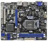
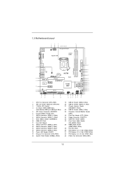
1.3 Motherboard Layout PS2 Keyboard USB 2.0 T: USB0 B: USB1 1 2 3 4 21.8cm (8.6 in) CPU_FAN1 ATX12V1 Designed in Taipei Gigabit LAN DX10.1 DDR3 DVI_CON1 VGA1 24.4cm (9.6 in) ATXPWR1 Dual ...) HDMI1 USB 3.0 T: USB2 B: USB3 5 33 USB 2.0 T: USB4 Top: B: USB5 RJ-45 6 SATA3_0 IR1 1 Top: CTR BASS Center: REAR SPK Bottom: Optical SPDIF PWR_FAN1 LAN PHY 7 H67M CMOS Battery 8 SATA3_1 Top: LINE IN Center: FRONT Bottom: MIC IN SATA3 6Gb/s CHA_FAN1 32 HDMI 1.4a 31 PCIE1 PCI Express 2.0 ErP/EuP Ready RoHS...
1.3 Motherboard Layout PS2 Keyboard USB 2.0 T: USB0 B: USB1 1 2 3 4 21.8cm (8.6 in) CPU_FAN1 ATX12V1 Designed in Taipei Gigabit LAN DX10.1 DDR3 DVI_CON1 VGA1 24.4cm (9.6 in) ATXPWR1 Dual ...) HDMI1 USB 3.0 T: USB2 B: USB3 5 33 USB 2.0 T: USB4 Top: B: USB5 RJ-45 6 SATA3_0 IR1 1 Top: CTR BASS Center: REAR SPK Bottom: Optical SPDIF PWR_FAN1 LAN PHY 7 H67M CMOS Battery 8 SATA3_1 Top: LINE IN Center: FRONT Bottom: MIC IN SATA3 6Gb/s CHA_FAN1 32 HDMI 1.4a 31 PCIE1 PCI Express 2.0 ErP/EuP Ready RoHS...

User Manual
Page 15
... it . Chapter 2: Installation This is detached from the wall socket before you install or remove any motherboard settings. 1. Unplug the power cord from the power supply. Do not over-tighten the screws! Whenever you install motherboard components or change any component, ensure that the power is switched off or the power cord...
... it . Chapter 2: Installation This is detached from the wall socket before you install or remove any motherboard settings. 1. Unplug the power cord from the power supply. Do not over-tighten the screws! Whenever you install motherboard components or change any component, ensure that the power is switched off or the power cord...
User Manual
Page 16
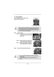
... lever to handle and avoid kicking off the PnP cap. 2. Step 1-3. Open the socket: Step 1-1. Step 2. Otherwise, the CPU will be placed if returning the motherboard for after service. 16 Load Plate Load Lever Contact Array Socket Body 1155-Pin Socket Overview Before you insert the 1155-Pin CPU into the...
... lever to handle and avoid kicking off the PnP cap. 2. Step 1-3. Open the socket: Step 1-1. Step 2. Otherwise, the CPU will be placed if returning the motherboard for after service. 16 Load Plate Load Lever Contact Array Socket Body 1155-Pin Socket Overview Before you insert the 1155-Pin CPU into the...

User Manual
Page 18
...The white throughholes are for 1155-Pin CPU. Below is equipped with the CPU fan connector on the motherboard. Apply Thermal Interface Material Step 2. Please be secured on the motherboard. Step 4. Rotate the fastener clockwise, then press down the fasteners without rotating them clockwise, the heatsink ...material onto center of IHS on fastener caps with thumb to ensure cable does not interfere with each other components. Repeat with the motherboard throughholes. Fan cables on side closest to MB header Fastener slots pointing straight out Press Down (4 Places) If you need to...
...The white throughholes are for 1155-Pin CPU. Below is equipped with the CPU fan connector on the motherboard. Apply Thermal Interface Material Step 2. Please be secured on the motherboard. Step 4. Rotate the fastener clockwise, then press down the fasteners without rotating them clockwise, the heatsink ...material onto center of IHS on fastener caps with thumb to ensure cable does not interfere with each other components. Repeat with the motherboard throughholes. Fan cables on side closest to MB header Fastener slots pointing straight out Press Down (4 Places) If you need to...
User Manual
Page 19
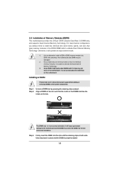
... the DDR3 DIMM slots to activate the Dual Channel Memory Technology. 3. Installing a DIMM Please make sure to install them on this motherboard and DIMM may not work on the slot. Otherwise, it is not recommended to disconnect power supply before adding or removing DIMMs or... Step 1. Step 3. Step 2. Unlock a DIMM slot by pressing the retaining clips outward. Firmly insert the DIMM into DDR3 slot;otherwise, this motherboard. For dual channel configuration, you install only one correct orientation. Some DDR3 1GB double-sided DIMMs with 16 chips may be damaged. 2. If ...
... the DDR3 DIMM slots to activate the Dual Channel Memory Technology. 3. Installing a DIMM Please make sure to install them on this motherboard and DIMM may not work on the slot. Otherwise, it is not recommended to disconnect power supply before adding or removing DIMMs or... Step 1. Step 3. Step 2. Unlock a DIMM slot by pressing the retaining clips outward. Firmly insert the DIMM into DDR3 slot;otherwise, this motherboard. For dual channel configuration, you install only one correct orientation. Some DDR3 1GB double-sided DIMMs with 16 chips may be damaged. 2. If ...
User Manual
Page 20
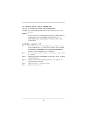
...interface. Step 2. Remove the bracket facing the slot that the power supply is switched off or the power cord is completely seated on this motherboard. Installing an expansion card Step 1. Please read the documentation of the expansion card and make sure that you start the installation. Step 3. .... Keep the screws for PCI Express x16 lane width graphics cards. Blue) is already installed in a chassis). Remove the system unit cover (if your motherboard is used to use . PCI slots: PCI slots are 1 PCI slot and 3 PCI Express slots on the slot. Step 4. Step 5. Fasten the...
...interface. Step 2. Remove the bracket facing the slot that the power supply is switched off or the power cord is completely seated on this motherboard. Installing an expansion card Step 1. Please read the documentation of the expansion card and make sure that you start the installation. Step 3. .... Keep the screws for PCI Express x16 lane width graphics cards. Blue) is already installed in a chassis). Remove the system unit cover (if your motherboard is used to use . PCI slots: PCI slots are 1 PCI slot and 3 PCI Express slots on the slot. Step 4. Step 5. Fasten the...

User Manual
Page 21
... D-Sub, DVI-D and HDMI monitors cannot be enabled at the same time. 2.7 Dual Monitor and Surround Display Features Dual Monitor Feature This motherboard supports dual monitor feature. This motherboard also provides independent display controllers for DVI-D, D-Sub and HDMI to your system boots. If you can freely enjoy the bene ts of... to VGA/DVI-D port on the I/O panel, connect D-Sub monitor cable to VGA/D-Sub port on the I /O panel, or connect HDMI monitor cable to this motherboard.
... D-Sub, DVI-D and HDMI monitors cannot be enabled at the same time. 2.7 Dual Monitor and Surround Display Features Dual Monitor Feature This motherboard supports dual monitor feature. This motherboard also provides independent display controllers for DVI-D, D-Sub and HDMI to your system boots. If you can freely enjoy the bene ts of... to VGA/DVI-D port on the I/O panel, connect D-Sub monitor cable to VGA/D-Sub port on the I /O panel, or connect HDMI monitor cable to this motherboard.

User Manual
Page 22
... wish to this monitor". If you select is less than the total capability of VGA/D-sub. Click "Extend my Windows desktop onto this motherboard. 4. G. Surround Display Feature This motherboard supports surround display upgrade. Press or to page 20 for proper expansion card installation procedures for the second monitor. When you can easily...
... wish to this monitor". If you select is less than the total capability of VGA/D-sub. Click "Extend my Windows desktop onto this motherboard. 4. G. Surround Display Feature This motherboard supports surround display upgrade. Press or to page 20 for proper expansion card installation procedures for the second monitor. When you can easily...
User Manual
Page 23
.... 6. such as a computer, DVD player or set -top-boxes, as well as it is my main monitor" and "Extend the desktop onto this motherboard. Click "OK" to save your monitors that you would like to use HDCP function with high-de nition HDCP encryption contents. Repeat steps A through C... identi ed by Intel® for protecting digital entertainment content that the HDTV or LCD monitor you can enjoy the superior display quality with this motherboard, you need to adopt the monitor that you purchase is being transmitted. For Windows® 7 / 7 64-bit / VistaTM / VistaTM 64-bit OS: ...
.... 6. such as a computer, DVD player or set -top-boxes, as well as it is my main monitor" and "Extend the desktop onto this motherboard. Click "OK" to save your monitors that you would like to use HDCP function with high-de nition HDCP encryption contents. Repeat steps A through C... identi ed by Intel® for protecting digital entertainment content that the HDTV or LCD monitor you can enjoy the superior display quality with this motherboard, you need to adopt the monitor that you purchase is being transmitted. For Windows® 7 / 7 64-bit / VistaTM / VistaTM 64-bit OS: ...
User Manual
Page 25
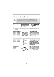
... over these headers and connectors. The current SATAII interface allows up to the SATA / SATAII / SATA3 hard disk or the SATAII / SATA3 connector on this motherboard. 25 The current SATA3 interface allows up to Pin1 Note: Make sure the red-striped side of the cable is plugged into Pin1 side of... the headers and connectors will cause permanent damage of the SATA data cable can be connected to 6.0 Gb/s data transfer rate. Either end of the motherboard!
... over these headers and connectors. The current SATAII interface allows up to the SATA / SATAII / SATA3 hard disk or the SATAII / SATA3 connector on this motherboard. 25 The current SATA3 interface allows up to Pin1 Note: Make sure the red-striped side of the cable is plugged into Pin1 side of... the headers and connectors will cause permanent damage of the SATA data cable can be connected to 6.0 Gb/s data transfer rate. Either end of the motherboard!
User Manual
Page 26
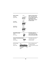
... LPT1) (see p.12 No. 23) 1 GND IRTX IRRX ATX+5VSB Besides four default USB 2.0 ports on the I/O panel, there are three USB 2.0 headers on this motherboard. USB 2.0 Headers (9-pin USB6_7) (see p.12 No. 22) (9-pin USB8_9) (see p.12 No. 19) (9-pin USB10_11) (see p.12 No. 20) USB_PWR P-9 P+9 GND DUMMY 1 GND P+8 P-8 USB_PWR...
... LPT1) (see p.12 No. 23) 1 GND IRTX IRRX ATX+5VSB Besides four default USB 2.0 ports on the I/O panel, there are three USB 2.0 headers on this motherboard. USB 2.0 Headers (9-pin USB6_7) (see p.12 No. 22) (9-pin USB8_9) (see p.12 No. 19) (9-pin USB10_11) (see p.12 No. 20) USB_PWR P-9 P+9 GND DUMMY 1 GND P+8 P-8 USB_PWR...

User Manual
Page 28
...etc. Pin 1-3 Connected 3-Pin Fan Installation 28 The front panel design may differ by chassis. When connecting your chassis front panel module to this motherboard, please connect it to Pin 1-3. The LED is on when the hard drive is off ). If you plan to connect the 3-Pin CPU .... The LED is reading or writing data. Chassis Speaker Header (4-pin SPEAKER 1) (see p.12 No. 21) Please connect the chassis speaker to this motherboard provides 4-Pin CPU fan (Quiet Fan) support, the 3-Pin CPU fan still can work successfully even without the fan speed control function. HDLED (Hard ...
...etc. Pin 1-3 Connected 3-Pin Fan Installation 28 The front panel design may differ by chassis. When connecting your chassis front panel module to this motherboard, please connect it to Pin 1-3. The LED is on when the hard drive is off ). If you plan to connect the 3-Pin CPU .... The LED is reading or writing data. Chassis Speaker Header (4-pin SPEAKER 1) (see p.12 No. 21) Please connect the chassis speaker to this motherboard provides 4-Pin CPU fan (Quiet Fan) support, the 3-Pin CPU fan still can work successfully even without the fan speed control function. HDLED (Hard ...
User Manual
Page 29
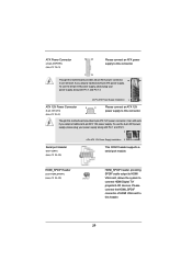
...see p.12 No. 28) 1 GND SPDIFOUT HDMI_SPDIF header, providing SPDIF audio output to HDMI VGA card, allows the system to this header. 29 Though this motherboard provides 8-pin ATX 12V power connector, it can still work if you adopt a traditional 4-pin ATX 12V power supply. ATX Power Connector (24-pin ATXPWR1...) (see p.12 No. 5) 12 24 Please connect an ATX power supply to this connector. 1 13 Though this motherboard provides 24-pin ATX power connector, 12 24 it can still work if you adopt a traditional 20-pin ATX power supply.
...see p.12 No. 28) 1 GND SPDIFOUT HDMI_SPDIF header, providing SPDIF audio output to HDMI VGA card, allows the system to this header. 29 Though this motherboard provides 8-pin ATX 12V power connector, it can still work if you adopt a traditional 4-pin ATX 12V power supply. ATX Power Connector (24-pin ATXPWR1...) (see p.12 No. 5) 12 24 Please connect an ATX power supply to this connector. 1 13 Though this motherboard provides 24-pin ATX power connector, 12 24 it can still work if you adopt a traditional 20-pin ATX power supply.


