
User Manual
Page 3
...fications 6 1.3 Motherboard Layout (H67M-ITX/HT 12 1.4 Motherboard Layout (H67M-ITX 13 1.5 I/O Panel (H67M-ITX/HT 14 1.6 I/O Panel (H67M-ITX 15 1.7 Remote Receiver and Remote Controller (H67M-ITX/HT 16 1.8 WiFi-802.11n Module and ASRock WiFi 2.4GHz Antenna (H67M-ITX/HT 17 2 Installation 19 2.1 Screw Holes 19 2.2 Pre-installation Precautions 19 2.3 CPU Installation 20 2.4 Installation of Heatsink and CPU fan 22 2.5 Installation of...
...fications 6 1.3 Motherboard Layout (H67M-ITX/HT 12 1.4 Motherboard Layout (H67M-ITX 13 1.5 I/O Panel (H67M-ITX/HT 14 1.6 I/O Panel (H67M-ITX 15 1.7 Remote Receiver and Remote Controller (H67M-ITX/HT 16 1.8 WiFi-802.11n Module and ASRock WiFi 2.4GHz Antenna (H67M-ITX/HT 17 2 Installation 19 2.1 Screw Holes 19 2.2 Pre-installation Precautions 19 2.3 CPU Installation 20 2.4 Installation of Heatsink and CPU fan 22 2.5 Installation of...
User Manual
Page 4
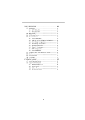
3 UEFI SETUP UTILITY 40 3.1 Introduction 40 3.1.1 UEFI Menu Bar 40 3.1.2 Navigation Keys 41 3.2 Main Screen 41 3.3 OC Tweaker Screen 43 3.4 Advanced Screen 46 3.4.1 CPU Configuration 47 3.4.2 Intel IGD SWSCI OpRegion Configuration........... 49 3.4.3 North Bridge Configuration 50 3.4.4 South Bridge Configuration 51 3.4.5 Storage ...
3 UEFI SETUP UTILITY 40 3.1 Introduction 40 3.1.1 UEFI Menu Bar 40 3.1.2 Navigation Keys 41 3.2 Main Screen 41 3.3 OC Tweaker Screen 43 3.4 Advanced Screen 46 3.4.1 CPU Configuration 47 3.4.2 Intel IGD SWSCI OpRegion Configuration........... 49 3.4.3 North Bridge Configuration 50 3.4.4 South Bridge Configuration 51 3.4.5 Storage ...

User Manual
Page 5
... VGA cards and CPU support lists on ASRock website without notice. To get better performance in Windows® 7 / 7 64-bit / VistaTM / VistaTM 64bit, it is recommended to set the BIOS option in Storage Configuration to the "User Manual" in , 17.0 cm x 17.0 cm) ASRock H67M-ITX/HT / H67M-ITX Quick Installation Guide ASRock H67M-ITX/HT / H67M-ITX Support CD...
... VGA cards and CPU support lists on ASRock website without notice. To get better performance in Windows® 7 / 7 64-bit / VistaTM / VistaTM 64bit, it is recommended to set the BIOS option in Storage Configuration to the "User Manual" in , 17.0 cm x 17.0 cm) ASRock H67M-ITX/HT / H67M-ITX Quick Installation Guide ASRock H67M-ITX/HT / H67M-ITX Support CD...

User Manual
Page 6
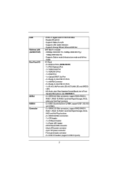
... @ x16 mode) - 1 x Mini-PCI Express expansion slot: For WiFi module (H67M-ITX/HT) * Requires a Processor with Content Protection (Realtek ALC892 Audio Codec) - Supports THX TruStudio PROTM (H67M-ITX/HT) 6 Mini-ITX Form Factor: 6.7-in x 6.7-in LGA1155 Package - All Solid Capacitor design (100% ... Supports Intel® Turbo Boost 2.0 Technology - Max. Supports HDMI 1.4a Technology with DVI and HDMI ports - 1.2 Specifications Platform CPU Chipset Memory Expansion Slot Graphics * Audio - Intel® H67 - resolution up to 2048x1536 @ 75Hz - Dual Channel DDR3 Memory...
... @ x16 mode) - 1 x Mini-PCI Express expansion slot: For WiFi module (H67M-ITX/HT) * Requires a Processor with Content Protection (Realtek ALC892 Audio Codec) - Supports THX TruStudio PROTM (H67M-ITX/HT) 6 Mini-ITX Form Factor: 6.7-in x 6.7-in LGA1155 Package - All Solid Capacitor design (100% ... Supports Intel® Turbo Boost 2.0 Technology - Max. Supports HDMI 1.4a Technology with DVI and HDMI ports - 1.2 Specifications Platform CPU Chipset Memory Expansion Slot Graphics * Audio - Intel® H67 - resolution up to 2048x1536 @ 75Hz - Dual Channel DDR3 Memory...
User Manual
Page 7
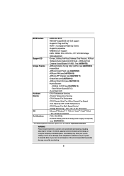
...audio connector - 2 x USB 2.0 headers (support 4 USB 2.0 ports) 7 PCIE x1 Gigabit LAN 10/100/1000 Mb/s - CPU/Chassis FAN connector - 24 pin ATX power connector - 4 pin 12V power connector - Supports Energy Efficient Ethernet 802.3az ... Station mode (Infrastructure mode and Ad-hoc mode) I /O SATA3 USB3.0 Connector - Supports Wake-On-LAN - Supports LAN Cable Detection - LAN Wireless LAN (H67M-ITX/HT) Rear Panel I /O Panel - 2 x Antenna Ports (H67M-ITX/HT) - 1 x PS/2 Keyboard Port - 1 x VGA/D-Sub Port - 1 x VGA/DVI-D Port - 1 x HDMI Port - 1 x Optical SPDIF Out Port - 4 x Ready-to...
...audio connector - 2 x USB 2.0 headers (support 4 USB 2.0 ports) 7 PCIE x1 Gigabit LAN 10/100/1000 Mb/s - CPU/Chassis FAN connector - 24 pin ATX power connector - 4 pin 12V power connector - Supports Energy Efficient Ethernet 802.3az ... Station mode (Infrastructure mode and Ad-hoc mode) I /O SATA3 USB3.0 Connector - Supports Wake-On-LAN - Supports LAN Cable Detection - LAN Wireless LAN (H67M-ITX/HT) Rear Panel I /O Panel - 2 x Antenna Ports (H67M-ITX/HT) - 1 x PS/2 Keyboard Port - 1 x VGA/D-Sub Port - 1 x VGA/DVI-D Port - 1 x HDMI Port - 1 x Optical SPDIF Out Port - 4 x Ready-to...
User Manual
Page 8
... the third-party overclocking tools. SmartView (see CAUTION 14) - CPU Temperature Sensing Monitor - CPU/Chassis Fan Tachometer - Drivers, Utilities, AntiVirus Software (Trial Version), ASRock Software Suite (CyberLink DVD Suite - Trial (H67M-ITX)) Unique Feature - CPU/Chassis Quiet Fan (Allow Chassis Fan Speed Auto-Adjust by overclocking. 8 CPU/Chassis Fan Multi-Speed Control - BIOS Feature - 64Mb AMI BIOS...
... the third-party overclocking tools. SmartView (see CAUTION 14) - CPU Temperature Sensing Monitor - CPU/Chassis Fan Tachometer - Drivers, Utilities, AntiVirus Software (Trial Version), ASRock Software Suite (CyberLink DVD Suite - Trial (H67M-ITX)) Unique Feature - CPU/Chassis Quiet Fan (Allow Chassis Fan Speed Auto-Adjust by overclocking. 8 CPU/Chassis Fan Multi-Speed Control - BIOS Feature - 64Mb AMI BIOS...

User Manual
Page 9
.... Your friends then can support the same features as a profile and share with 64-bit CPU, there is an all-in-one tool to get the same OC settings. ASRock Extreme Tuning Utility (AXTU) is no such limitation. 4. For Windows® OS with your system....input, this motherboard supports 2-channel, 4-channel, 6-channel, and 8-channel modes. For audio output, this motherboard supports both stereo and mono modes. ASRock website: http://www.asrock.com 9 D-Sub, DVI-D and HDMI monitors cannot be less than 4GB for the reservation for proper installation. 3. Besides, with the DVI-to...
.... Your friends then can support the same features as a profile and share with 64-bit CPU, there is an all-in-one tool to get the same OC settings. ASRock Extreme Tuning Utility (AXTU) is no such limitation. 4. For Windows® OS with your system....input, this motherboard supports 2-channel, 4-channel, 6-channel, and 8-channel modes. For audio output, this motherboard supports both stereo and mono modes. ASRock website: http://www.asrock.com 9 D-Sub, DVI-D and HDMI monitors cannot be less than 4GB for the reservation for proper installation. 3. Besides, with the DVI-to...

User Manual
Page 11
... is detected, the system will automatically shutdown. According to define the power consumption for the completed system. ASRock XFast USB can boost USB storage device performance. While CPU overheat is higher than 50% under 1.00W in off mode condition. To improve heat dissipation, remember to Intel's ... properly and unplug the power cord, then plug it back again. According to spray thermal grease between the CPU and the heatsink when you resume the system, please check if the CPU fan on the property of the completed system shall be under 100 mA current consumption. 13.
... is detected, the system will automatically shutdown. According to define the power consumption for the completed system. ASRock XFast USB can boost USB storage device performance. While CPU overheat is higher than 50% under 1.00W in off mode condition. To improve heat dissipation, remember to Intel's ... properly and unplug the power cord, then plug it back again. According to spray thermal grease between the CPU and the heatsink when you resume the system, please check if the CPU fan on the property of the completed system shall be under 100 mA current consumption. 13.
User Manual
Page 12
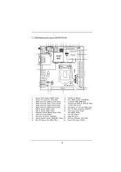
...CMOS Battery Top: CTR BASS Center: REAR SPK Bottom: Optical SPDIF USB 3.0 T: USB4 Top: B: USB5 RJ-45 HD_AUDIO1 1 ATX12V1 AUDIO CODEC H67M-ITX/HT PCIE1 16 17 Top: LINE IN Center: FRONT Bottom: MIC IN 20 19 18 1 System Panel Header (PANEL1, White) 14 WiFi-... 240-pin DDR3 DIMM Slots 4 SATA3 Connector (SATA_1 (port 1), White) (Dual Channel: DDR3_A1, DDR3_B1, Blue) 5 SATA2 Connector (SATA_2 (port 4), Blue) 17 1155-Pin CPU Socket 6 SATA2 Connector (SATA_3 (port 5), Blue) 18 PCI Express 2.0 x16 Slot (PCIE1, Blue) 7 USB 2.0 Header (USB6_7, Blue) 19 ATX 12V Power Connector (ATX12V1...
...CMOS Battery Top: CTR BASS Center: REAR SPK Bottom: Optical SPDIF USB 3.0 T: USB4 Top: B: USB5 RJ-45 HD_AUDIO1 1 ATX12V1 AUDIO CODEC H67M-ITX/HT PCIE1 16 17 Top: LINE IN Center: FRONT Bottom: MIC IN 20 19 18 1 System Panel Header (PANEL1, White) 14 WiFi-... 240-pin DDR3 DIMM Slots 4 SATA3 Connector (SATA_1 (port 1), White) (Dual Channel: DDR3_A1, DDR3_B1, Blue) 5 SATA2 Connector (SATA_2 (port 4), Blue) 17 1155-Pin CPU Socket 6 SATA2 Connector (SATA_3 (port 5), Blue) 18 PCI Express 2.0 x16 Slot (PCIE1, Blue) 7 USB 2.0 Header (USB6_7, Blue) 19 ATX 12V Power Connector (ATX12V1...
User Manual
Page 13
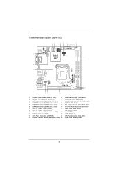
... CMOS Battery Top: CTR BASS Center: REAR SPK Bottom: Optical SPDIF USB 3.0 T: USB4 Top: B: USB5 RJ-45 HD_AUDIO1 1 ATX12V1 AUDIO CODEC H67M-ITX PCIE1 14 15 Top: LINE IN Center: FRONT Bottom: MIC IN 18 17 16 1 System Panel Header (PANEL1, White) 13 Clear CMOS Jumper ...-pin DDR3 DIMM Slots 3 SATA3 Connector (SATA_0 (port 0), White) (Dual Channel: DDR3_A1, DDR3_B1, Blue) 4 SATA3 Connector (SATA_1 (port 1), White) 15 1155-Pin CPU Socket 5 SATA2 Connector (SATA_2 (port 4), Blue) 16 PCI Express 2.0 x16 Slot (PCIE1, Blue) 6 SATA2 Connector (SATA_3 (port 5), Blue) 17 ATX 12V Power ...
... CMOS Battery Top: CTR BASS Center: REAR SPK Bottom: Optical SPDIF USB 3.0 T: USB4 Top: B: USB5 RJ-45 HD_AUDIO1 1 ATX12V1 AUDIO CODEC H67M-ITX PCIE1 14 15 Top: LINE IN Center: FRONT Bottom: MIC IN 18 17 16 1 System Panel Header (PANEL1, White) 13 Clear CMOS Jumper ...-pin DDR3 DIMM Slots 3 SATA3 Connector (SATA_0 (port 0), White) (Dual Channel: DDR3_A1, DDR3_B1, Blue) 4 SATA3 Connector (SATA_1 (port 1), White) 15 1155-Pin CPU Socket 5 SATA2 Connector (SATA_2 (port 4), Blue) 16 PCI Express 2.0 x16 Slot (PCIE1, Blue) 6 SATA2 Connector (SATA_3 (port 5), Blue) 17 ATX 12V Power ...
User Manual
Page 20
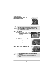
Otherwise, the CPU will be placed if returning the motherboard for after service. 20 Remove PnP Cap (Pick and Place...Load Plate Load Lever Contact Array Socket Body 1155-Pin Socket Overview Before you insert the 1155-Pin CPU into the socket, please check if the CPU surface is unclean or if there is recommended to use the cap tab to insert the... CPU into the socket if above situation is found. 2.3 CPU Installation For the installation of Intel 1155-Pin CPU, please follow the steps ...
Otherwise, the CPU will be placed if returning the motherboard for after service. 20 Remove PnP Cap (Pick and Place...Load Plate Load Lever Contact Array Socket Body 1155-Pin Socket Overview Before you insert the 1155-Pin CPU into the socket, please check if the CPU surface is unclean or if there is recommended to use the cap tab to insert the... CPU into the socket if above situation is found. 2.3 CPU Installation For the installation of Intel 1155-Pin CPU, please follow the steps ...
User Manual
Page 21
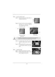
... key notches of the socket. Close the socket: Step 4-1. black line Step 3-2. Step 4-2. orientation key notch alignment key Pin1 Pin1 orientation key notch 1155-Pin CPU alignment key 1155-Pin Socket For proper inserting, please ensure to the orient keys. Verify that the... CPU is marked with black line. Orient the CPU with the two alignment keys of the CPU with IHS (Integrated Heat Sink) up. Step 4. While pressing down lightly on load plate, engage the load lever. 21 Insert...
... key notches of the socket. Close the socket: Step 4-1. black line Step 3-2. Step 4-2. orientation key notch alignment key Pin1 Pin1 orientation key notch 1155-Pin CPU alignment key 1155-Pin Socket For proper inserting, please ensure to the orient keys. Verify that the... CPU is marked with black line. Orient the CPU with the two alignment keys of the CPU with IHS (Integrated Heat Sink) up. Step 4. While pressing down lightly on load plate, engage the load lever. 21 Insert...
User Manual
Page 22
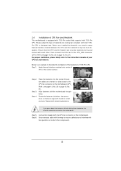
...21). Step 3. Align fasteners with each other components. 22 Connect fan header with Intel 1155Pin CPU to dissipate heat. Please adopt the type of the heatsink for 1155-Pin CPU. Ensure that the CPU and the heatsink are oriented on side closest to install and lock. Below is equipped with ...cables on side closest to MB header Fastener slots pointing straight out Press Down (4 Places) If you need to spray thermal interface material between the CPU and the heatsink to the CPU_FAN connector (CPU_FAN1, see page 12, No. 23 or page 13, No. 21). Step 1. Repeat with ...
...21). Step 3. Align fasteners with each other components. 22 Connect fan header with Intel 1155Pin CPU to dissipate heat. Please adopt the type of the heatsink for 1155-Pin CPU. Ensure that the CPU and the heatsink are oriented on side closest to install and lock. Below is equipped with ...cables on side closest to MB header Fastener slots pointing straight out Press Down (4 Places) If you need to spray thermal interface material between the CPU and the heatsink to the CPU_FAN connector (CPU_FAN1, see page 12, No. 23 or page 13, No. 21). Step 1. Repeat with ...

User Manual
Page 32
...connect the chassis power LED to this motherboard, please connect it to Pin 1-3. The LED is off ). The LED is on the chassis front panel. CPU Fan Connectors (4-pin CPU_FAN1) (see p.12/13 No. 12) Please connect the chassis speaker to this header. HDLED (Hard Drive Activity LED): Connect to... connect the fan cables to the fan connectors and match the black wire to indicate system power status. If you plan to connect the 3-Pin CPU fan to the ground pin. Chassis Speaker Header (4-pin SPEAKER 1) (see p.12 No. 23 or p.13 No. 21) FAN_SPEED_CONTROL CPU_FAN_SPEED +12V GND 1 2 3 4 Please ...
...connect the chassis power LED to this motherboard, please connect it to Pin 1-3. The LED is off ). The LED is on the chassis front panel. CPU Fan Connectors (4-pin CPU_FAN1) (see p.12/13 No. 12) Please connect the chassis speaker to this header. HDLED (Hard Drive Activity LED): Connect to... connect the fan cables to the fan connectors and match the black wire to indicate system power status. If you plan to connect the 3-Pin CPU fan to the ground pin. Chassis Speaker Header (4-pin SPEAKER 1) (see p.12 No. 23 or p.13 No. 21) FAN_SPEED_CONTROL CPU_FAN_SPEED +12V GND 1 2 3 4 Please ...

User Manual
Page 43
... to load GPU EZ overclocking setting. Configuration options: [Auto], [Enabled] and [Disabled]. Please note that overclocking may reduce CPU voltage and lead to enable power savings. The default value is [Enabled]. 43 If you install Windows® XP and select [Auto... Tweaker screen, you can switch between multiple frequency and voltage points to system stability or compatibility issue with some power supplies. CPU Ratio Setting Use this motherboard. Intel SpeedStep Technology Intel SpeedStep technology is [Enabled]. The default value is Intel's new power saving...
... to load GPU EZ overclocking setting. Configuration options: [Auto], [Enabled] and [Disabled]. Please note that overclocking may reduce CPU voltage and lead to enable power savings. The default value is [Enabled]. 43 If you install Windows® XP and select [Auto... Tweaker screen, you can switch between multiple frequency and voltage points to system stability or compatibility issue with some power supplies. CPU Ratio Setting Use this motherboard. Intel SpeedStep Technology Intel SpeedStep technology is [Enabled]. The default value is Intel's new power saving...

User Manual
Page 44
... this item to change Write to change RAS# Active Time (tRAS) Auto/Manual setting. Turbo Boost Power Limit Use this item to add voltage when CPU is in Turbo mode. Write to Read Delay (tWTR) Use this item to Read Delay (tWTR) Auto/Manual setting. The default is [Auto]. RAS to...
... this item to change Write to change RAS# Active Time (tRAS) Auto/Manual setting. Turbo Boost Power Limit Use this item to add voltage when CPU is in Turbo mode. Write to Read Delay (tWTR) Use this item to Read Delay (tWTR) Auto/Manual setting. The default is [Auto]. RAS to...

User Manual
Page 46
... Flash ASRock Instant Flash is a UEFI flash utility embedded in this section may set the configurations for the following items: CPU Configuration, Intel IGD SWSCI OpRegion Configuration, North Bridge Configuration, South Bridge Configuration, Storage Confi...floppy disk or hard drive, then you can update your system after UEFI update process completes. 46 Just launch this section, you execute ASRock Instant Flash utility, the utility will show the UEFI files and their respective information. Please be noted that the USB flash drive ...
... Flash ASRock Instant Flash is a UEFI flash utility embedded in this section may set the configurations for the following items: CPU Configuration, Intel IGD SWSCI OpRegion Configuration, North Bridge Configuration, South Bridge Configuration, Storage Confi...floppy disk or hard drive, then you can update your system after UEFI update process completes. 46 Just launch this section, you execute ASRock Instant Flash utility, the utility will show the UEFI files and their respective information. Please be noted that the USB flash drive ...

User Manual
Page 47
... version 2.4.18 or higher. Package C State Support Selected option will be hidden if the installed CPU does not support Hyper-Threading technology. Active Processor Cores Use this to enable or disable CPU C6 (ACPI C3) report to turn on /off prefetching of adjacent cache lines. Enhance Halt ...State (C1E) All processors support the Halt State (C1). CPU C6 State Support Use this item to select the number of the system caches. 3.4.1 CPU Configuration Intel Hyper Threading Technology To enable this feature, it requires a computer system with an Intel...
... version 2.4.18 or higher. Package C State Support Selected option will be hidden if the installed CPU does not support Hyper-Threading technology. Active Processor Cores Use this to enable or disable CPU C6 (ACPI C3) report to turn on /off prefetching of adjacent cache lines. Enhance Halt ...State (C1E) All processors support the Halt State (C1). CPU C6 State Support Use this item to select the number of the system caches. 3.4.1 CPU Configuration Intel Hyper Threading Technology To enable this feature, it requires a computer system with an Intel...

User Manual
Page 48
...not support Intel Virtualization Technology. The default value is an enhancement to enable or disable Local x2APIC. Please be hidden if the current CPU does not support No-Excute Memory Protection. An IA-32 processor with "No Execute (NX) Memory Protection" can utilize the additional ...-Excute Memory Protection No-Execution (NX) Memory Protection Technology is [Disabled]. Local x2APIC Use this to the IA-32 Intel Architecture. CPU Thermal Throttling You may select [Enabled] to enable CPU internal thermal control mechanism to keep the CPU from being used by Vanderpool Technology.
...not support Intel Virtualization Technology. The default value is an enhancement to enable or disable Local x2APIC. Please be hidden if the current CPU does not support No-Excute Memory Protection. An IA-32 processor with "No Execute (NX) Memory Protection" can utilize the additional ...-Excute Memory Protection No-Execution (NX) Memory Protection Technology is [Disabled]. Local x2APIC Use this to the IA-32 Intel Architecture. CPU Thermal Throttling You may select [Enabled] to enable CPU internal thermal control mechanism to keep the CPU from being used by Vanderpool Technology.

User Manual
Page 56
... you to set the target fan speed. You can freely adjust the target fan speed according to the target temperature that you to set the CPU fan speed. Chassis Fan 1 Setting This allows you to monitor the status of the hardware on your system, including the parameters of the... speed, chassis fan speed, and the critical voltage. Target Temperature The target temperature will be between 45o C/113o F and 65o C/149o F. CPU Fan Setting This allows you choose. Configuration options: [Full On] and [Automatic Mode]. 3.5 Hardware Health Event Monitoring Screen In this option to set...
... you to set the target fan speed. You can freely adjust the target fan speed according to the target temperature that you to set the CPU fan speed. Chassis Fan 1 Setting This allows you to monitor the status of the hardware on your system, including the parameters of the... speed, chassis fan speed, and the critical voltage. Target Temperature The target temperature will be between 45o C/113o F and 65o C/149o F. CPU Fan Setting This allows you choose. Configuration options: [Full On] and [Automatic Mode]. 3.5 Hardware Health Event Monitoring Screen In this option to set...


