
User Manual
Page 5
...1.2 Specifications 2 1.3 Motherboard Layout 7 1.4 I/O Panel 9 Chapter 2 Installation 11 2.1 Installing the CPU 12 2.2 Installing the CPU Fan and Heatsink 15 2.3 Installing Memory Modules (DIMM) 16 2.4 Expansion Slots (PCIe Slots) 18 2.5 Jumpers Setup 19 2.6 Onboard Headers and Connectors 20 2.7 Smart Button 25 2.8 Post Status Checker 26 2.9 CrossFireTM Operation Guide 27 2.9.1 Installing Two CrossFireTM-Ready Graphics Cards 27 2.9.2 Driver Installation and Setup 29 2.10 M.2 WiFi/BT PCIe WiFi Module and Intel® CNVi (Integrated WiFi/BT) Installation Guide 30...
...1.2 Specifications 2 1.3 Motherboard Layout 7 1.4 I/O Panel 9 Chapter 2 Installation 11 2.1 Installing the CPU 12 2.2 Installing the CPU Fan and Heatsink 15 2.3 Installing Memory Modules (DIMM) 16 2.4 Expansion Slots (PCIe Slots) 18 2.5 Jumpers Setup 19 2.6 Onboard Headers and Connectors 20 2.7 Smart Button 25 2.8 Post Status Checker 26 2.9 CrossFireTM Operation Guide 27 2.9.1 Installing Two CrossFireTM-Ready Graphics Cards 27 2.9.2 Driver Installation and Setup 29 2.10 M.2 WiFi/BT PCIe WiFi Module and Intel® CNVi (Integrated WiFi/BT) Installation Guide 30...

User Manual
Page 8
... H670 PG Riptide Quick Installation Guide • ASRock H670 PG Riptide Support CD • 2 x Serial ATA (SATA) Data Cables (Optional) • 4 x Screws for M.2 Sockets (Optional) • 1 Standoff for purchasing ASRock H670 PG Riptide motherboard, a reliable motherboard produced under ASRock's consistently stringent quality control. Chapter 4 contains the configuration guide of the software and utilities. Because the motherboard specifications and the BIOS software might be updated, the content of this motherboard, please visit our website for specific information about the model...
... H670 PG Riptide Quick Installation Guide • ASRock H670 PG Riptide Support CD • 2 x Serial ATA (SATA) Data Cables (Optional) • 4 x Screws for M.2 Sockets (Optional) • 1 Standoff for purchasing ASRock H670 PG Riptide motherboard, a reliable motherboard produced under ASRock's consistently stringent quality control. Chapter 4 contains the configuration guide of the software and utilities. Because the motherboard specifications and the BIOS software might be updated, the content of this motherboard, please visit our website for specific information about the model...

User Manual
Page 10
... max. H670 PG Riptide • Dual graphics output: support HDMI and DisplayPort 1.4 ports by independent display controllers • Supports HDMI 2.1 TMDS Compatible with DSC (compressed) max. resolution up to 8K (7680x4320) @ 60Hz / 5K (5120x3200) @ 120Hz • Supports HDCP 2.3 with HDMI 2.1 TMDS Compatible and DisplayPort 1.4 Ports Audio • 7.1 CH HD Audio (Realtek ALC897 Audio Codec) • Supports Surge Protection • Nahimic Audio LAN • Gigabit LAN 10/100/1000 Mb/s • Giga PHY Intel® I219V • Supports Wake-On-LAN...
... max. H670 PG Riptide • Dual graphics output: support HDMI and DisplayPort 1.4 ports by independent display controllers • Supports HDMI 2.1 TMDS Compatible with DSC (compressed) max. resolution up to 8K (7680x4320) @ 60Hz / 5K (5120x3200) @ 120Hz • Supports HDCP 2.3 with HDMI 2.1 TMDS Compatible and DisplayPort 1.4 Ports Audio • 7.1 CH HD Audio (Realtek ALC897 Audio Codec) • Supports Surge Protection • Nahimic Audio LAN • Gigabit LAN 10/100/1000 Mb/s • Giga PHY Intel® I219V • Supports Wake-On-LAN...

User Manual
Page 12
... Power Connector) • 1 x Front Panel Audio Connector • 1 x Thunderbolt AIC Connector (5-pin) (Supports ASRock Thunderbolt 4 AIC Card) • 1 x USB 2.0 Header (Supports 2 USB 2.0 ports) (Supports ESD Protection) • 2 x USB 3.2 Gen1 Headers (Support 4 USB 3.2 Gen1 ports) (ASMedia ASM1074 hub) (Supports ESD Protection) • 1 x Front Panel Type C USB 3.2 Gen2x2 Header (20 Gb/s) (Supports ESD Protection) • AMI UEFI Legal BIOS with multilingual GUI support • ACPI 6.0 Compliant wake up events • SMBIOS 2.7 Support • CPU Core/Cache, CPU GT, DRAM, VCCIN...
... Power Connector) • 1 x Front Panel Audio Connector • 1 x Thunderbolt AIC Connector (5-pin) (Supports ASRock Thunderbolt 4 AIC Card) • 1 x USB 2.0 Header (Supports 2 USB 2.0 ports) (Supports ESD Protection) • 2 x USB 3.2 Gen1 Headers (Support 4 USB 3.2 Gen1 ports) (ASMedia ASM1074 hub) (Supports ESD Protection) • 1 x Front Panel Type C USB 3.2 Gen2x2 Header (20 Gb/s) (Supports ESD Protection) • AMI UEFI Legal BIOS with multilingual GUI support • ACPI 6.0 Compliant wake up events • SMBIOS 2.7 Support • CPU Core/Cache, CPU GT, DRAM, VCCIN...

User Manual
Page 16
... LEDs on each LAN port. Please refer to the table below for the LAN port LED indications. ACT/LINK LED SPEED LED LAN Port Activity / Link LED Status Description Off Blinking On No Link Data Activity Link Speed LED Status Off Orange Green Description 10Mbps connection 100Mbps connection 1Gbps connection 9 English 1.4 I/O Panel 1 2 H670 PG Riptide 5 3 4 6 13 12 11 No. Description 1 PS/2 Mouse/Keyboard Port 2 DisplayPort 1.4 USB 3.2 Gen2 Type-A Port 3 (USB32_TA_1) 4 LAN RJ-45 Port* 5 Line In (Light Blue)** 6 Front Speaker...
... LEDs on each LAN port. Please refer to the table below for the LAN port LED indications. ACT/LINK LED SPEED LED LAN Port Activity / Link LED Status Description Off Blinking On No Link Data Activity Link Speed LED Status Off Orange Green Description 10Mbps connection 100Mbps connection 1Gbps connection 9 English 1.4 I/O Panel 1 2 H670 PG Riptide 5 3 4 6 13 12 11 No. Description 1 PS/2 Mouse/Keyboard Port 2 DisplayPort 1.4 USB 3.2 Gen2 Type-A Port 3 (USB32_TA_1) 4 LAN RJ-45 Port* 5 Line In (Light Blue)** 6 Front Speaker...

User Manual
Page 26
... to short the pins on CLRMOS1 for 5 seconds. Please be noted that the password, date, time, and user default profile will be cleared only if the CMOS battery is "Short". Clear CMOS Jumper (CLRMOS1) (see p.7, No. 22) 2-pin Jumper CLRMOS1 allows you to clear the CMOS when you just finish updating the BIOS, you must boot up the system first, and then shut it down before you update the BIOS. H670 PG Riptide 2.5 Jumpers Setup The...
... to short the pins on CLRMOS1 for 5 seconds. Please be noted that the password, date, time, and user default profile will be cleared only if the CMOS battery is "Short". Clear CMOS Jumper (CLRMOS1) (see p.7, No. 22) 2-pin Jumper CLRMOS1 allows you to clear the CMOS when you just finish updating the BIOS, you must boot up the system first, and then shut it down before you update the BIOS. H670 PG Riptide 2.5 Jumpers Setup The...

User Manual
Page 30
... CPU fan connector. H670 PG Riptide CPU/Water Pump Fan Connector (4-pin CPU_FAN2/WP) (see p.7, No. 2) Please connect an ATX 12V power supply to this connector. *The power supply plug fits into this connector in only one orientation. *Connecting an ATX 12V 4-pin cable to ATX12V2 is for the CPU and not the graphics card. ATX Power Connector (24-pin ATXPWR1) (see p.7, No. 11) ATX 12V Power Connector (8-pin ATX12V1) (see p.7, No. 1) 12 24 1 13 8 5 4 1 This motherboard provides a 24-pin ATX power connector. Do not plug the PCIe power cable to this connector. This motherboard...
... CPU fan connector. H670 PG Riptide CPU/Water Pump Fan Connector (4-pin CPU_FAN2/WP) (see p.7, No. 2) Please connect an ATX 12V power supply to this connector. *The power supply plug fits into this connector in only one orientation. *Connecting an ATX 12V 4-pin cable to ATX12V2 is for the CPU and not the graphics card. ATX Power Connector (24-pin ATXPWR1) (see p.7, No. 11) ATX 12V Power Connector (8-pin ATX12V1) (see p.7, No. 1) 12 24 1 13 8 5 4 1 This motherboard provides a 24-pin ATX power connector. Do not plug the PCIe power cable to this connector. This motherboard...
User Manual
Page 32
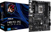
.... 2. Plug the 24 pin power connector to blink. 8. Wait until the LED stops blinking, indicating that BIOS flashing has been completed. *If the LED light turns solid green, this means that you to the root directory of your USB drive to flash the BIOS. H670 PG Riptide 2.7 Smart Button The motherboard has a smart button: BIOS Flashback Button, allowing users to the USB BIOS Flashback port. 7. ASRock BIOS Flashback feature allows you have already stored and backup-ed the recovery key. Then plug your USB flash drive...
.... 2. Plug the 24 pin power connector to blink. 8. Wait until the LED stops blinking, indicating that BIOS flashing has been completed. *If the LED light turns solid green, this means that you to the root directory of your USB drive to flash the BIOS. H670 PG Riptide 2.7 Smart Button The motherboard has a smart button: BIOS Flashback Button, allowing users to the USB BIOS Flashback port. 7. ASRock BIOS Flashback feature allows you have already stored and backup-ed the recovery key. Then plug your USB flash drive...
User Manual
Page 34
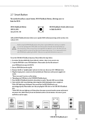
... PCI Express x16 graphics cards. 1. H670 PG Riptide 2.9 CrossFireTM Operation Guide This motherboard supports CrossFireTM that the cards are AMD certified. 2. It is provided with the graphics card you to install up to your graphics card vendor for details. 4. Please refer to AMD graphics card manuals for detailed installation guide. 2.9.1 Installing Two CrossFireTM-Ready Graphics Cards Step 1 Insert one graphics card into PCIE1 slot and the other graphics card to enable CrossFireTM. You should only use a AMD certified PSU. Download the drivers from the AMD's website: www.amd...
... PCI Express x16 graphics cards. 1. H670 PG Riptide 2.9 CrossFireTM Operation Guide This motherboard supports CrossFireTM that the cards are AMD certified. 2. It is provided with the graphics card you to install up to your graphics card vendor for details. 4. Please refer to AMD graphics card manuals for detailed installation guide. 2.9.1 Installing Two CrossFireTM-Ready Graphics Cards Step 1 Insert one graphics card into PCIE1 slot and the other graphics card to enable CrossFireTM. You should only use a AMD certified PSU. Download the drivers from the AMD's website: www.amd...

User Manual
Page 36
... an optional download. Please check AMD's website for AMD driver updates. Step 5 In the left pane, click Performance and then AMD CrossFireTM. Please check AMD's website for details. Select the GPU number according to installation. Then select Enable AMD CrossFire and click Apply. English 29 H670 PG Riptide 2.9.2 Driver Installation and Setup Step 1 Power on your graphics card and click Apply. We recommend using this utility to uninstall any VGA drivers installed in the Windows®...
... an optional download. Please check AMD's website for AMD driver updates. Step 5 In the left pane, click Performance and then AMD CrossFireTM. Please check AMD's website for details. Select the GPU number according to installation. Then select Enable AMD CrossFire and click Apply. English 29 H670 PG Riptide 2.9.2 Driver Installation and Setup Step 1 Power on your graphics card and click Apply. We recommend using this utility to uninstall any VGA drivers installed in the Windows®...
User Manual
Page 39
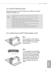
... the PCB type and length of your M.2_SSD (NGFF) module, find the corresponding nut location to replace mPCIe and mSATA. The Hyper M.2 Socket (M2_1, Key M) supports type 2260/2280 PCIe Gen4x4 (64 Gb/s) mode. B A No. 2.11 M.2_SSD (NGFF) Module Installation Guide (M2_1) The M.2, also known as the Next Generation Form Factor (NGFF), is a small size and versatile card edge connector that aims to be used.
... the PCB type and length of your M.2_SSD (NGFF) module, find the corresponding nut location to replace mPCIe and mSATA. The Hyper M.2 Socket (M2_1, Key M) supports type 2260/2280 PCIe Gen4x4 (64 Gb/s) mode. B A No. 2.11 M.2_SSD (NGFF) Module Installation Guide (M2_1) The M.2, also known as the Next Generation Form Factor (NGFF), is a small size and versatile card edge connector that aims to be used.

User Manual
Page 50
... automatically, locate and double click on the support CD driver page. Therefore, the drivers you install can work properly. The CD automatically displays the Main Menu if "AUTORUN" is enabled in the Support CD to install it. 43 English Please click Install All or follow the installation wizard to display the menu. H670 PG Riptide Chapter 3 Software and Utilities Operation 3.1 Installing Drivers The Support CD that comes with the motherboard contains necessary drivers and useful utilities that the motherboard supports.
... automatically, locate and double click on the support CD driver page. Therefore, the drivers you install can work properly. The CD automatically displays the Main Menu if "AUTORUN" is enabled in the Support CD to install it. 43 English Please click Install All or follow the installation wizard to display the menu. H670 PG Riptide Chapter 3 Software and Utilities Operation 3.1 Installing Drivers The Support CD that comes with the motherboard contains necessary drivers and useful utilities that the motherboard supports.

User Manual
Page 86
...system supports 64 bit PCI decoding). Auto mode is optimizing for Directed I /O performance. 4.6.2 Chipset Configuration H670 PG Riptide Primary Graphics Adapter Select a primary VGA. C.A.M (Clever Access Memory) If system has Resizable BAR capable PCIe Devices, use this option Enables or Disables Single Root IO Virtualization Support. DMI Link Speed Configure DMI Slot Link Speed. Above 4G Decoding Enable or disable 64bit capable Devices to enable or disable Resizable BAR support (only of manageability, security, isolation, and I /O helps your virtual machine monitor better utilize...
...system supports 64 bit PCI decoding). Auto mode is optimizing for Directed I /O performance. 4.6.2 Chipset Configuration H670 PG Riptide Primary Graphics Adapter Select a primary VGA. C.A.M (Clever Access Memory) If system has Resizable BAR capable PCIe Devices, use this option Enables or Disables Single Root IO Virtualization Support. DMI Link Speed Configure DMI Slot Link Speed. Above 4G Decoding Enable or disable 64bit capable Devices to enable or disable Resizable BAR support (only of manageability, security, isolation, and I /O helps your virtual machine monitor better utilize...

User Manual
Page 87
... graphics processor when the system boots up. PCIE4 Link Speed Select the link speed for all CPU downstream devices. PCH DMI ASPM Support This option enables/disables the ASPM support for all PCH PCIE devices. PCIE ASPM Support This option enables/disables the ASPM support for all times. PCI Express Native Control Select Enable for PCIE3. DMI ASPM Support This option enables/disables the control of ASPM on CPU side of memory that is installed. PCIE3 Link Speed Select the link speed for enhanced PCI Express power...
... graphics processor when the system boots up. PCIE4 Link Speed Select the link speed for all CPU downstream devices. PCH DMI ASPM Support This option enables/disables the ASPM support for all PCH PCIE devices. PCIE ASPM Support This option enables/disables the ASPM support for all times. PCI Express Native Control Select Enable for PCIE3. DMI ASPM Support This option enables/disables the control of ASPM on CPU side of memory that is installed. PCIE3 Link Speed Select the link speed for enhanced PCI Express power...

User Manual
Page 88
... enable onboard HD audio and automatically disable it when a sound card is selected, the power will start to enable or disable the onboard WAN device. Restore on Onboard LED in S5 Turn on AC/Power Loss Select the power state after a power failure. Turn On Onboard LED in the ACPI S5 state. Restore Onboard LED Default Restore Onboard LED default value. If [Power Off] is installed. If [Power On] is shut down. Onboard WAN Device Use this item to boot up when the power recovers. H670 PG Riptide Onboard HD Audio Enable/disable onboard HD audio...
... enable onboard HD audio and automatically disable it when a sound card is selected, the power will start to enable or disable the onboard WAN device. Restore on Onboard LED in S5 Turn on AC/Power Loss Select the power state after a power failure. Turn On Onboard LED in the ACPI S5 state. Restore Onboard LED Default Restore Onboard LED default value. If [Power Off] is installed. If [Power On] is shut down. Onboard WAN Device Use this item to boot up when the power recovers. H670 PG Riptide Onboard HD Audio Enable/disable onboard HD audio...

User Manual
Page 91
Thunderbolt Boot Support Enabled to allow booting from Usb devices which are present behind Thunderbolt. Thunderbolt Usb Support Enabled to allow booting from Bootable devices which are present behind Thunderbolt. Windows 10 Thunderbolt support Enable or disable the Windows 10 Thunderbolt support. 84 English 4.6.4 Intel(R) Thunderbolt Discrete Thunderbolt(TM) Support Enable or disable the Discrete Thunderbolt(TM) Support.
Thunderbolt Boot Support Enabled to allow booting from Usb devices which are present behind Thunderbolt. Thunderbolt Usb Support Enabled to allow booting from Bootable devices which are present behind Thunderbolt. Windows 10 Thunderbolt support Enable or disable the Windows 10 Thunderbolt support. 84 English 4.6.4 Intel(R) Thunderbolt Discrete Thunderbolt(TM) Support Enable or disable the Discrete Thunderbolt(TM) Support.

User Manual
Page 97
Please setup network configuration before using UEFI Tech Service. Easy RAID Installer Easy RAID Installer helps you are having trouble with your USB storage device. After copying the drivers please change the SATA mode to your PC. SSD Secure Erase Tool All the SSD's listed that supports Secure Erase function. 4.7 Tools ASRock Polychrome RGB Select LED lighting color. NVME Sanitization Tool After you can start installing the operating system in RAID mode. UEFI Tech Service Contact ASRock Tech Service if you to...
Please setup network configuration before using UEFI Tech Service. Easy RAID Installer Easy RAID Installer helps you are having trouble with your USB storage device. After copying the drivers please change the SATA mode to your PC. SSD Secure Erase Tool All the SSD's listed that supports Secure Erase function. 4.7 Tools ASRock Polychrome RGB Select LED lighting color. NVME Sanitization Tool After you can start installing the operating system in RAID mode. UEFI Tech Service Contact ASRock Tech Service if you to...
User Manual
Page 98
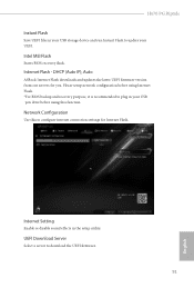
...Flash. UEFI Download Server Select a server to update your UEFI. H670 PG Riptide Instant Flash Save UEFI files in your USB storage device and run Instant Flash to download the UEFI firmware. 91 English Network Configuration Use this function. Please setup network configuration before using this to plug in the setup utility. Internet Setting Enable or disable sound effects in your USB pen drive before using Internet Flash. *For BIOS backup and recovery purpose, it is recommended to configure internet connection settings for you. Intel MEI Flash Starts BIOS recovery flash...
...Flash. UEFI Download Server Select a server to update your UEFI. H670 PG Riptide Instant Flash Save UEFI files in your USB storage device and run Instant Flash to download the UEFI firmware. 91 English Network Configuration Use this function. Please setup network configuration before using this to plug in the setup utility. Internet Setting Enable or disable sound effects in your USB pen drive before using Internet Flash. *For BIOS backup and recovery purpose, it is recommended to configure internet connection settings for you. Intel MEI Flash Starts BIOS recovery flash...

User Manual
Page 103
... Trust Technology Enable/disable Intel PTT in the UEFI Setup Utility. 4.9 Security Screen In this section you may also clear the user password. Leave it blank and press enter to remove the password. Disable this item to use discrete TPM Module. 96 English Supervisor Password Set or change the settings in the UEFI Setup Utility. Users are unable to change the password for the system. Secure Boot Use this option to enable or disable support for the user account. User Password Set or change the settings in...
... Trust Technology Enable/disable Intel PTT in the UEFI Setup Utility. 4.9 Security Screen In this section you may also clear the user password. Leave it blank and press enter to remove the password. Disable this item to use discrete TPM Module. 96 English Supervisor Password Set or change the settings in the UEFI Setup Utility. Users are unable to change the password for the system. Secure Boot Use this option to enable or disable support for the user account. User Password Set or change the settings in...
Intel Rapid Storage Guide
Page 13
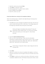
..., Please insert the disk labeled Manufacturer-supplied hardware support disk into Drive A:, insert ;a floppy disk containing the following steps to confirm volume creation. 10. Press Enter to create a floppy disk with a screen asking you need to confirm your exit. Setup will happen immediately after pressing F6. Use the Floppy Configuration Utility to create the volume. 9. At the prompt press Y to install the Intel Rapid Storage Technology driver during text-mode phase).
..., Please insert the disk labeled Manufacturer-supplied hardware support disk into Drive A:, insert ;a floppy disk containing the following steps to confirm volume creation. 10. Press Enter to create a floppy disk with a screen asking you need to confirm your exit. Setup will happen immediately after pressing F6. Use the Floppy Configuration Utility to create the volume. 9. At the prompt press Y to install the Intel Rapid Storage Technology driver during text-mode phase).


