User Manual
Page 2
... respect to the contents of this manual, ASRock does not provide warranty of any kind, either expressed or implied, including but not limited to the following two conditions: (1) this device may not cause harmful interference, and (2) this motherboard contains Perchlorate, a toxic substance controlled in Perchlorate Best Management Practices (BMP) regulations passed by...
... respect to the contents of this manual, ASRock does not provide warranty of any kind, either expressed or implied, including but not limited to the following two conditions: (1) this device may not cause harmful interference, and (2) this motherboard contains Perchlorate, a toxic substance controlled in Perchlorate Best Management Practices (BMP) regulations passed by...
User Manual
Page 3
Contents 1 Introduction 5 1.1 Package Contents 5 1.2 Specifications 6 1.3 Motherboard Layout (H61M-GS / H61M-S 11 1.4 I/O Panel (H61M-GS 12 1.5 I/O Panel (H61M-S 13 2 Installation 14 2.1 Screw Holes 14 2.2 Pre-installation Precautions 14 2.3 CPU Installation 15 2.4 Installation of Heatsink and CPU fan 17 2.5 Installation of Memory Modules (DIMM ...
Contents 1 Introduction 5 1.1 Package Contents 5 1.2 Specifications 6 1.3 Motherboard Layout (H61M-GS / H61M-S 11 1.4 I/O Panel (H61M-GS 12 1.5 I/O Panel (H61M-S 13 2 Installation 14 2.1 Screw Holes 14 2.2 Pre-installation Precautions 14 2.3 CPU Installation 15 2.4 Installation of Heatsink and CPU fan 17 2.5 Installation of Memory Modules (DIMM ...
User Manual
Page 5
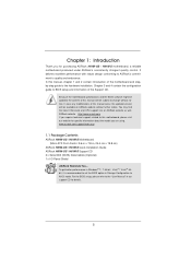
... "User Manual" in our support CD for purchasing ASRock H61M-GS / H61M-S motherboard, a reliable motherboard produced under ASRock's consistently stringent quality control. Because the motherboard specifications and the BIOS software might be updated, the content of the Support CD. www.asrock.com/support/index.asp 1.1 Package Contents ASRock H61M-GS / H61M-S Motherboard (Micro ATX Form Factor: 9.6-in x 7.8-in Storage Con...
... "User Manual" in our support CD for purchasing ASRock H61M-GS / H61M-S motherboard, a reliable motherboard produced under ASRock's consistently stringent quality control. Because the motherboard specifications and the BIOS software might be updated, the content of the Support CD. www.asrock.com/support/index.asp 1.1 Package Contents ASRock H61M-GS / H61M-S Motherboard (Micro ATX Form Factor: 9.6-in x 7.8-in Storage Con...

User Manual
Page 8
...CPU cores are not responsible for proper installation. 3. This motherboard supports Dual Channel Memory Technology. In OC DNA, you implement Dual Channel Memory Technology, make sure to get the same OC settings. ASRock website: http://www.asrock.com 8 - CPU/Chassis Fan Multi-Speed Control -...number of "Hyper Threading Technology", please check page 40. 2. The maximum shared memory size is defined by overclocking. ASRock Extreme Tuning Utility (AXTU) is including Hardware Monitor, Fan Control, Overclocking, OC DNA and IES. In IES (Intelligent Energy Saver...
...CPU cores are not responsible for proper installation. 3. This motherboard supports Dual Channel Memory Technology. In OC DNA, you implement Dual Channel Memory Technology, make sure to get the same OC settings. ASRock website: http://www.asrock.com 8 - CPU/Chassis Fan Multi-Speed Control -...number of "Hyper Threading Technology", please check page 40. 2. The maximum shared memory size is defined by overclocking. ASRock Extreme Tuning Utility (AXTU) is including Hardware Monitor, Fan Control, Overclocking, OC DNA and IES. In IES (Intelligent Energy Saver...
User Manual
Page 9
...hard drive must use SmartView feature, please make sure your OS version is the smart start experiencing the exciting motion controlled games. ASRock motherboards are exclusively equipped with friends on the property of PC gaming operation. Also, please do -date supported games! This convenient BIOS...friends and your computer and up -do not forget to pay attention to ASRock of ficial website or ASRock software support CD to your motherboard, and also download the free AIWI Lite from ASRock of ficial website regularly, we will continuously provide you to your ...
...hard drive must use SmartView feature, please make sure your OS version is the smart start experiencing the exciting motion controlled games. ASRock motherboards are exclusively equipped with friends on the property of PC gaming operation. Also, please do -date supported games! This convenient BIOS...friends and your computer and up -do not forget to pay attention to ASRock of ficial website or ASRock software support CD to your motherboard, and also download the free AIWI Lite from ASRock of ficial website regularly, we will continuously provide you to your ...
User Manual
Page 10
... Union to spray thermal grease between the CPU and the heatsink when you resume the system, please check if the CPU fan on the motherboard functions properly and unplug the power cord, then plug it back again. To meet the standard of the completed system shall be used. 13...10 Combo Cooler Option (C.C.O.) provides the flexible option to Intel's suggestion, the EuP ready power supply must meet EuP standard, an EuP ready motherboard and an EuP ready power supply are required. According to adopt three different CPU cooler types, Socket LGA 775, LGA 1155 and LGA 1156. Before...
... Union to spray thermal grease between the CPU and the heatsink when you resume the system, please check if the CPU fan on the motherboard functions properly and unplug the power cord, then plug it back again. To meet the standard of the completed system shall be used. 13...10 Combo Cooler Option (C.C.O.) provides the flexible option to Intel's suggestion, the EuP ready power supply must meet EuP standard, an EuP ready motherboard and an EuP ready power supply are required. According to adopt three different CPU cooler types, Socket LGA 775, LGA 1155 and LGA 1156. Before...
User Manual
Page 11
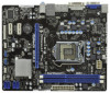
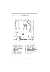
1.3 Motherboard Layout (H61M-GS / H61M-S) PS2 Mouse PS2 Keyboard 1 23 4 5 19.8cm (7.8 in) Designed in Taipei ErP/EuP Ready CPU_FAN1 ATX12V1 DX10.1 VGA1 24.4cm (9.6 in) DDR3 ATXPWR1 DDR3_B1 (64 ...
1.3 Motherboard Layout (H61M-GS / H61M-S) PS2 Mouse PS2 Keyboard 1 23 4 5 19.8cm (7.8 in) Designed in Taipei ErP/EuP Ready CPU_FAN1 ATX12V1 DX10.1 VGA1 24.4cm (9.6 in) DDR3 ATXPWR1 DDR3_B1 (64 ...
User Manual
Page 14
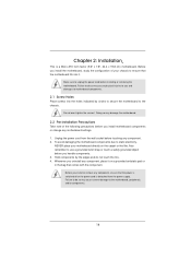
...3. Doing so may cause severe damage to do so may damage the motherboard. 2.2 Pre-installation Precautions Take note of your motherboard directly on a grounded antistatic pad or in the bag that the motherboard fits into the holes indicated by the edges and do so ...may cause physical injuries to you install the motherboard, study the configuration of the following precautions before you install motherboard components or change any component. 2. Failure to the motherboard, peripherals, and/or components. 14 Chapter 2: Installation This is ...
...3. Doing so may cause severe damage to do so may damage the motherboard. 2.2 Pre-installation Precautions Take note of your motherboard directly on a grounded antistatic pad or in the bag that the motherboard fits into the holes indicated by the edges and do so ...may cause physical injuries to you install the motherboard, study the configuration of the following precautions before you install motherboard components or change any component. 2. Failure to the motherboard, peripherals, and/or components. 14 Chapter 2: Installation This is ...

User Manual
Page 15
... degrees. 2.3 CPU Installation For the installation of Intel 1155-Pin CPU, please follow the steps below. Otherwise, the CPU will be placed if returning the motherboard for after service. 15 Disengaging the lever by depressing down and out on the socket. This cap must be seriously damaged. It is any bent...
... degrees. 2.3 CPU Installation For the installation of Intel 1155-Pin CPU, please follow the steps below. Otherwise, the CPU will be placed if returning the motherboard for after service. 15 Disengaging the lever by depressing down and out on the socket. This cap must be seriously damaged. It is any bent...
User Manual
Page 17
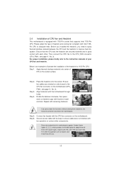
...the socket. Rotate the fastener clockwise, then press down the fasteners without rotating them clockwise, the heatsink cannot be noticed that this motherboard supports Combo Cooler Option (C.C.O.), which provides the flexible option to adopt three different CPU cooler types, Socket LGA 775, ... proper installation, please kindly refer to the instruction manuals of heatsink and cooling fan compliant with the CPU fan connector on the motherboard. Apply Thermal Interface Material Step 2. Connect fan header with Intel 1155Pin CPU to ensure cable does not interfere with each other...
...the socket. Rotate the fastener clockwise, then press down the fasteners without rotating them clockwise, the heatsink cannot be noticed that this motherboard supports Combo Cooler Option (C.C.O.), which provides the flexible option to adopt three different CPU cooler types, Socket LGA 775, ... proper installation, please kindly refer to the instruction manuals of heatsink and cooling fan compliant with the CPU fan connector on the motherboard. Apply Thermal Interface Material Step 2. Connect fan header with Intel 1155Pin CPU to ensure cable does not interfere with each other...

User Manual
Page 18
... at single channel mode. 1. Step 2. Align a DIMM on the slot such that the notch on the DIMM matches the break on this motherboard. Otherwise, it is properly seated. 18 Step 1. It will operate at both ends fully snap back in place and the DIMM is unable ... Memory Technology. 3. Step 3. Some DDR3 1GB double-sided DIMMs with 16 chips may be damaged. 2. 2.5 Installation of Memory Modules (DIMM) This motherboard provides two 240-pin DDR3 (Double Data Rate 3) DIMM slots, and supports Dual Channel Memory Technology. For dual channel configuration, you install only one ...
... at single channel mode. 1. Step 2. Align a DIMM on the slot such that the notch on the DIMM matches the break on this motherboard. Otherwise, it is properly seated. 18 Step 1. It will operate at both ends fully snap back in place and the DIMM is unable ... Memory Technology. 3. Step 3. Some DDR3 1GB double-sided DIMMs with 16 chips may be damaged. 2. 2.5 Installation of Memory Modules (DIMM) This motherboard provides two 240-pin DDR3 (Double Data Rate 3) DIMM slots, and supports Dual Channel Memory Technology. For dual channel configuration, you install only one ...
User Manual
Page 19
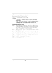
...: PCIE1 (PCIE x16 slot; Step 4. Step 5. Step 6. Step 3. Fasten the card to use . Blue) is completely seated on this motherboard. PCIE2 / PCIE3 (PCIE x1 slot; Remove the system unit cover (if your motherboard is already installed in a chassis). Please read the documentation of the expansion card and make sure that you start...
...: PCIE1 (PCIE x16 slot; Step 4. Step 5. Step 6. Step 3. Fasten the card to use . Blue) is completely seated on this motherboard. PCIE2 / PCIE3 (PCIE x1 slot; Remove the system unit cover (if your motherboard is already installed in a chassis). Please read the documentation of the expansion card and make sure that you start...
User Manual
Page 20
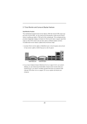
... the below steps: 1. Connect DVI-D monitor cable to VGA/DVI-D port on the I /O panel, and connect D-Sub monitor cable to this motherboard. If you have installed onboard VGA driver from our support CD to your system already, you haven't installed onboard VGA driver yet, please install onboard...enjoy the benefits of dual monitor feature without installing any add-on VGA card to VGA/D-Sub port on the I /O panel. This motherboard also provides independent display controllers for DVI-D and D-Sub to your system and restart your system boots. VGA/D-Sub port VGA/DVI-D port 2....
... the below steps: 1. Connect DVI-D monitor cable to VGA/DVI-D port on the I /O panel, and connect D-Sub monitor cable to this motherboard. If you have installed onboard VGA driver from our support CD to your system already, you haven't installed onboard VGA driver yet, please install onboard...enjoy the benefits of dual monitor feature without installing any add-on VGA card to VGA/D-Sub port on the I /O panel. This motherboard also provides independent display controllers for DVI-D and D-Sub to your system and restart your system boots. VGA/D-Sub port VGA/DVI-D port 2....

User Manual
Page 21
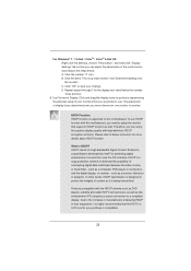
... Set up a surround display environment: 1. A. C. Right-click the display icon and select "Attached", if necessary. Surround Display Feature This motherboard supports surround display upgrade. Please refer to the following steps to apply these new values. Please refer to page 19 for proper expansion card installation..." button to display a large number on PCI Express VGA card driver to install them again. 5. Click "Extend my Windows desktop onto this motherboard. 4. If you use multiple monitors with your card, one , two, three and four. 21 Install the onboard VGA driver and the add...
... Set up a surround display environment: 1. A. C. Right-click the display icon and select "Attached", if necessary. Surround Display Feature This motherboard supports surround display upgrade. Please refer to the following steps to apply these new values. Please refer to page 19 for proper expansion card installation..." button to display a large number on PCI Express VGA card driver to install them again. 5. Click "Extend my Windows desktop onto this motherboard. 4. If you use multiple monitors with your card, one , two, three and four. 21 Install the onboard VGA driver and the add...
User Manual
Page 22
What is supported on this motherboard. Products compatible with the HDCP scheme such as DVD players, satellite and cable HDTV set-top-boxes, as well as a computer, DVD player or set-... refer to a compliant display. such as few entertainment PCs requires a secure connection to below . HDCP is my main monitor" and "Extend the desktop onto this motherboard, you can adjust the parameters of your change. B. such as well. Click the number "2" icon. To use .
What is supported on this motherboard. Products compatible with the HDCP scheme such as DVD players, satellite and cable HDTV set-top-boxes, as well as a computer, DVD player or set-... refer to a compliant display. such as few entertainment PCs requires a secure connection to below . HDCP is my main monitor" and "Extend the desktop onto this motherboard, you can adjust the parameters of your change. B. such as well. Click the number "2" icon. To use .
User Manual
Page 24
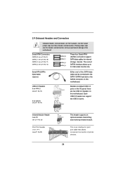
...damage of printer devices. 24 The current SATAII interface allows up to the SATA / SATAII hard disk or the SATAII connector on this motherboard. Serial ATA (SATA) Data Cable (Optional) Either end of the SATA data cable can support two USB 2.0 ports. Infrared Module... connectors support SATA data cables for print port cable that allows convenient connection of the motherboard! 2.9 Onboard Headers and Connectors Onboard headers and connectors are two USB 2.0 headers on this motherboard. Placing jumper caps over these headers and connectors. Each USB 2.0 header can be ...
...damage of printer devices. 24 The current SATAII interface allows up to the SATA / SATAII hard disk or the SATAII connector on this motherboard. Serial ATA (SATA) Data Cable (Optional) Either end of the SATA data cable can support two USB 2.0 ports. Infrared Module... connectors support SATA data cables for print port cable that allows convenient connection of the motherboard! 2.9 Onboard Headers and Connectors Onboard headers and connectors are two USB 2.0 headers on this motherboard. Placing jumper caps over these headers and connectors. Each USB 2.0 header can be ...
User Manual
Page 26
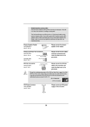
...Please connect an ATX power supply to the ground pin. The LED is on this header. When connecting your chassis front panel module to this motherboard, please connect it to the CPU fan connector on when the hard drive is reading or writing data. Pin 1-3 Connected 3-Pin Fan Installation ... CPU_FAN1) (see p.11 No. 1) PWR_FAN_SPEED +12V GND Please connect the fan cables to the fan connectors and match the black wire to this motherboard provides 4-Pin CPU fan (Quiet Fan) support, the 3-Pin CPU fan still can work successfully even without the fan speed control function.
...Please connect an ATX power supply to the ground pin. The LED is on this header. When connecting your chassis front panel module to this motherboard, please connect it to the CPU fan connector on when the hard drive is reading or writing data. Pin 1-3 Connected 3-Pin Fan Installation ... CPU_FAN1) (see p.11 No. 1) PWR_FAN_SPEED +12V GND Please connect the fan cables to the fan connectors and match the black wire to this motherboard provides 4-Pin CPU fan (Quiet Fan) support, the 3-Pin CPU fan still can work successfully even without the fan speed control function.
User Manual
Page 27
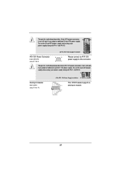
...Pin 1 and Pin 5. 8 5 Serial port Header (9-pin COM1) (see p.11 No. 4) 8 5 4 1 Please connect an ATX 12V power supply to this connector. Though this motherboard provides 8-pin ATX 12V power connector, it can still work if you adopt a traditional 4-pin ATX 12V power supply. To use the 4-pin ATX power... (8-pin ATX12V1) (see p.11 No. 17) 4-Pin ATX 12V Power Supply Installation 4 1 This COM1 header supports a serial port module. 27 Though this motherboard provides 24-pin ATX power connector, 12 24 it can still work if you adopt a traditional 20-pin ATX power supply.
...Pin 1 and Pin 5. 8 5 Serial port Header (9-pin COM1) (see p.11 No. 4) 8 5 4 1 Please connect an ATX 12V power supply to this connector. Though this motherboard provides 8-pin ATX 12V power connector, it can still work if you adopt a traditional 4-pin ATX 12V power supply. To use the 4-pin ATX power... (8-pin ATX12V1) (see p.11 No. 17) 4-Pin ATX 12V Power Supply Installation 4 1 This COM1 header supports a serial port module. 27 Though this motherboard provides 24-pin ATX power connector, 12 24 it can still work if you adopt a traditional 20-pin ATX power supply.
User Manual
Page 28
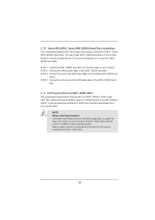
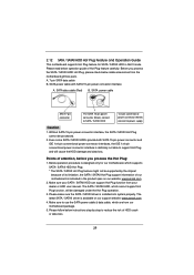
... devices. Intel® H61 chipset provides hardware support for Advanced Host controller Interface (AHCI), a new programming interface for the action to the motherboard's SATAII con- STEP 2: Connect the SATA power cable to install the SATA / SATAII hard disks. nector. This section will guide you ...to the SATA / SATAII hard disk. 2.10 Serial ATA (SATA) / Serial ATAII (SATAII) Hard Disks Installation This motherboard adopts Intel® H61 chipset that it is called "Hot Plug" for SATA host controllers developed thru a joint industry effort. However, please note...
... devices. Intel® H61 chipset provides hardware support for Advanced Host controller Interface (AHCI), a new programming interface for the action to the motherboard's SATAII con- STEP 2: Connect the SATA power cable to install the SATA / SATAII hard disks. nector. This section will guide you ...to the SATA / SATAII hard disk. 2.10 Serial ATA (SATA) / Serial ATAII (SATAII) Hard Disks Installation This motherboard adopts Intel® H61 chipset that it is called "Hot Plug" for SATA host controllers developed thru a joint industry effort. However, please note...
User Manual
Page 29
... data loss. Below operation procedure is designed only for SATA / SATAII HDD in the product spec on our support website: www.asrock.com 4. Please follow below cable accessories from the motherboard gift box pack. Even some SATA / SATAII HDDs provide both SATA 15-pin power connector and IDE 1x4-pin conventional power...
... data loss. Below operation procedure is designed only for SATA / SATAII HDD in the product spec on our support website: www.asrock.com 4. Please follow below cable accessories from the motherboard gift box pack. Even some SATA / SATAII HDDs provide both SATA 15-pin power connector and IDE 1x4-pin conventional power...


