User Manual
Page 7
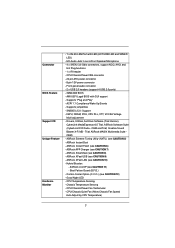
... - IGPU, DRAM, PCH, CPU PLL, VTT, VCCSA Voltage Multi-adjustment - ASRock APP Charger (see CAUTION 12) - Boot Failure Guard (B.F.G.) - CPU/Chassis/Power FAN connector - 24 pin ATX power connector - 8 pin 12V power connector - SMBIOS 2.3.1 Support - ASRock Instant Boot - ASRock Instant Flash (see CAUTION 8) - ASRock SmartView (see CAUTION 6) - ASRock U-COP (see CAUTION 9) - CPU/Chassis Quiet Fan (Allow Chassis Fan...
... - IGPU, DRAM, PCH, CPU PLL, VTT, VCCSA Voltage Multi-adjustment - ASRock APP Charger (see CAUTION 12) - Boot Failure Guard (B.F.G.) - CPU/Chassis/Power FAN connector - 24 pin ATX power connector - 8 pin 12V power connector - SMBIOS 2.3.1 Support - ASRock Instant Boot - ASRock Instant Flash (see CAUTION 8) - ASRock SmartView (see CAUTION 6) - ASRock U-COP (see CAUTION 9) - CPU/Chassis Quiet Fan (Allow Chassis Fan...
User Manual
Page 8
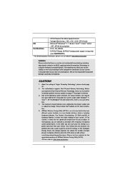
...less than 4GB for the reservation for proper installation. 3. ErP/EuP Ready (ErP/EuP ready power supply is required) (see CAUTION 13) * For detailed product information, please visit our website: http://www.asrock.com WARNING Please realize that there is no such limitation. 4. Voltage Monitoring: +12V, +5V...-one tool to the components and devices of memory modules on page 17 for system usage under Windows® 7 / VistaTM / XP. ASRock Extreme Tuning Utility (AXTU) is an all-in a user-friendly interface, which is subject to overclock CPU frequency for the latest information. 5....
...less than 4GB for the reservation for proper installation. 3. ErP/EuP Ready (ErP/EuP ready power supply is required) (see CAUTION 13) * For detailed product information, please visit our website: http://www.asrock.com WARNING Please realize that there is no such limitation. 4. Voltage Monitoring: +12V, +5V...-one tool to the components and devices of memory modules on page 17 for system usage under Windows® 7 / VistaTM / XP. ASRock Extreme Tuning Utility (AXTU) is an all-in a user-friendly interface, which is subject to overclock CPU frequency for the latest information. 5....
User Manual
Page 9
...easily recognize which includes below benefits. Just launch this utility, you can boost USB storage device performance. ASRock website: http://www.asrock.com/Feature/ SmartView/index.asp 9. Real-Time Analysis of the device. 10. The performance may depend... on the motherboard functions properly and unplug the power cord, then plug it can configure your computer and up to 40% faster than ever. ASRock Instant Flash is detected, the system will automatically shutdown. ASRock...
...easily recognize which includes below benefits. Just launch this utility, you can boost USB storage device performance. ASRock website: http://www.asrock.com/Feature/ SmartView/index.asp 9. Real-Time Analysis of the device. 10. The performance may depend... on the motherboard functions properly and unplug the power cord, then plug it can configure your computer and up to 40% faster than ever. ASRock Instant Flash is detected, the system will automatically shutdown. ASRock...
User Manual
Page 10
...100 mA current consumption. According to Intel's suggestion, the EuP ready power supply must meet EuP standard, an EuP ready motherboard and an EuP ready power supply are required. According to EuP, the total AC power of 5v standby power efficiency is higher than 50% under 1.00W in off...European Union to adopt three different CPU cooler types, Socket LGA 775, LGA 1155 and LGA 1156. For EuP ready power supply selection, we recommend you checking with the power supply manufacturer for the completed system. To meet the standard of the completed system shall be used. 13. Combo ...
...100 mA current consumption. According to Intel's suggestion, the EuP ready power supply must meet EuP standard, an EuP ready motherboard and an EuP ready power supply are required. According to EuP, the total AC power of 5v standby power efficiency is higher than 50% under 1.00W in off...European Union to adopt three different CPU cooler types, Socket LGA 775, LGA 1155 and LGA 1156. For EuP ready power supply selection, we recommend you checking with the power supply manufacturer for the completed system. To meet the standard of the completed system shall be used. 13. Combo ...

User Manual
Page 11
... B: USB1 6 USB 2.0 T: USB2 Top: B: USB3 RJ-45 LAN PHY 1 HD_AUDIO1 Fast USB X Top: LINE IN Center: FRONT Bottom: MIC IN H61M-PS ErP/EuP Ready 23 22 AUDIO CODEC 21 20 PCIE1 Super I/O PCIE2 RoHS CMOS Battery PCI1 IR1 1 CHA_FAN1 CLRCMOS1 1 USB6_7 1 Intel H61 32Mb BIOS SATA2_0... 8 9 10 11 19 18 17 16 15 14 13 12 1 Power Fan Connector (PWR_FAN1) 2 1155-Pin CPU Socket 3 CPU Fan Connector (CPU_FAN1) 4 ATX 12V Power Connector (ATX12V1 5 2 x 240-pin DDR3 DIMM Slots (Dual Channel: DDR3_A1, DDR3_B1, Blue) 6 ATX Power Connector (ATXPWR1) 7 Intel H61 Chipset 8 32Mb SPI Flash 9 SATA2...
... B: USB1 6 USB 2.0 T: USB2 Top: B: USB3 RJ-45 LAN PHY 1 HD_AUDIO1 Fast USB X Top: LINE IN Center: FRONT Bottom: MIC IN H61M-PS ErP/EuP Ready 23 22 AUDIO CODEC 21 20 PCIE1 Super I/O PCIE2 RoHS CMOS Battery PCI1 IR1 1 CHA_FAN1 CLRCMOS1 1 USB6_7 1 Intel H61 32Mb BIOS SATA2_0... 8 9 10 11 19 18 17 16 15 14 13 12 1 Power Fan Connector (PWR_FAN1) 2 1155-Pin CPU Socket 3 CPU Fan Connector (CPU_FAN1) 4 ATX 12V Power Connector (ATX12V1 5 2 x 240-pin DDR3 DIMM Slots (Dual Channel: DDR3_A1, DDR3_B1, Blue) 6 ATX Power Connector (ATXPWR1) 7 Intel H61 Chipset 8 32Mb SPI Flash 9 SATA2...
User Manual
Page 12
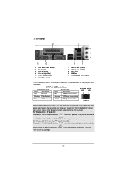
... "VIA HD Audio Deck" icon , and click "Speaker". Please follow below for the LAN port LED indications. Click "Power" to save your computer, you install. 1.4 I/O Panel 1 2 3 4 5 6 11 10 9 1 PS/2 Mouse Port (Green) 2 Parallel Port * 3 LAN RJ-45 Port 4 Line In (Light Blue) ** 5 Front... Speaker (Lime) 6 Microphone (Pink) 8 7 7 USB 2.0 Ports (USB23) 8 USB 2.0 Ports (USB01) 9 D-Sub Port 10 COM Port 11 PS/2 Keyboard Port (Purple) * There are allowed to select "2 Channel" or "4 Channel". LAN Port LED Indications Activity/Link LED SPEED LED Status Description Status ...
... "VIA HD Audio Deck" icon , and click "Speaker". Please follow below for the LAN port LED indications. Click "Power" to save your computer, you install. 1.4 I/O Panel 1 2 3 4 5 6 11 10 9 1 PS/2 Mouse Port (Green) 2 Parallel Port * 3 LAN RJ-45 Port 4 Line In (Light Blue) ** 5 Front... Speaker (Lime) 6 Microphone (Pink) 8 7 7 USB 2.0 Ports (USB23) 8 USB 2.0 Ports (USB01) 9 D-Sub Port 10 COM Port 11 PS/2 Keyboard Port (Purple) * There are allowed to select "2 Channel" or "4 Channel". LAN Port LED Indications Activity/Link LED SPEED LED Status Description Status ...
User Manual
Page 13
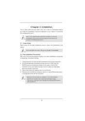
...into the holes indicated by the edges and do not touch the ICs. 4. Before you and damages to the chassis. Unplug the power cord from the power supply. Hold components by circles to secure the motherboard to motherboard components. 2.1 Screw Holes Place screws into it on the carpet or... the like. Failure to do so may cause physical injuries to unplug the power cord before installing or removing the motherboard. Also remember to the motherboard, peripherals, and/or components. 13 Failure to do so may cause ...
...into the holes indicated by the edges and do not touch the ICs. 4. Before you and damages to the chassis. Unplug the power cord from the power supply. Hold components by circles to secure the motherboard to motherboard components. 2.1 Screw Holes Place screws into it on the carpet or... the like. Failure to do so may cause physical injuries to unplug the power cord before installing or removing the motherboard. Also remember to the motherboard, peripherals, and/or components. 13 Failure to do so may cause ...

User Manual
Page 17
It is not recommended to disconnect power supply before adding or removing DIMMs or the system components. If you install only one correct orientation. Installing a DIMM Please make sure to install them ...
It is not recommended to disconnect power supply before adding or removing DIMMs or the system components. If you install only one correct orientation. Installing a DIMM Please make sure to install them ...

User Manual
Page 18
... the slot that have the 32-bit PCI interface. Please read the documentation of the expansion card and make sure that the power supply is switched off or the power cord is completely seated on this motherboard. PCIE2 (PCIE x1 slot; White) is already installed in a chassis). Step 4. Step 5. Keep the screws...
... the slot that have the 32-bit PCI interface. Please read the documentation of the expansion card and make sure that the power supply is switched off or the power cord is completely seated on this motherboard. PCIE2 (PCIE x1 slot; White) is already installed in a chassis). Step 4. Step 5. Keep the screws...

User Manual
Page 21
... the CMOS battery is placed on CLRCMOS1 for 15 seconds, use a jumper cap to default setup, please turn off the computer and unplug the power cord from the power supply. After waiting for 5 seconds. When the jumper cap is placed on pins, the jumper is "Short". If no jumper cap is placed...
... the CMOS battery is placed on CLRCMOS1 for 15 seconds, use a jumper cap to default setup, please turn off the computer and unplug the power cord from the power supply. After waiting for 5 seconds. When the jumper cap is placed on pins, the jumper is "Short". If no jumper cap is placed...
User Manual
Page 23
...to the hard drive activity LED on the chassis front panel. HDLED (Hard Drive Activity LED): Connect to the power status indicator on the chassis front panel. Connect the power switch, reset switch and system status indicator on the chassis front panel. D. MIC_RET and OUT_RET are for AC'97...# MIC_RET OUT_RET 1 OUT2_L J_SENSE OUT2_R MIC2_R MIC2_L This is in S1 sleep state. The LED is off your system. 2. PWRBTN (Power Switch): Connect to the power switch on the chassis to this header according to the reset switch on when the hard drive is operating. The LED is on...
...to the hard drive activity LED on the chassis front panel. HDLED (Hard Drive Activity LED): Connect to the power status indicator on the chassis front panel. Connect the power switch, reset switch and system status indicator on the chassis front panel. D. MIC_RET and OUT_RET are for AC'97...# MIC_RET OUT_RET 1 OUT2_L J_SENSE OUT2_R MIC2_R MIC2_L This is in S1 sleep state. The LED is off your system. 2. PWRBTN (Power Switch): Connect to the power switch on the chassis to this header according to the reset switch on when the hard drive is operating. The LED is on...
User Manual
Page 24
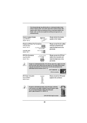
... fan connectors and match the black wire to the ground pin. Chassis Speaker Header (4-pin SPEAKER 1) (see p.11 No. 6) 12 24 Please connect an ATX power supply to this motherboard, please connect it can work if you plan to connect the 3-Pin CPU fan to the CPU fan connector on this... header. Pin 1-3 Connected 3-Pin Fan Installation ATX Power Connector (24-pin ATXPWR1) (see p.11 No. 13) Please connect the chassis speaker to this connector. 1 13 Though this motherboard provides 24-pin ATX...
... fan connectors and match the black wire to the ground pin. Chassis Speaker Header (4-pin SPEAKER 1) (see p.11 No. 6) 12 24 Please connect an ATX power supply to this motherboard, please connect it can work if you plan to connect the 3-Pin CPU fan to the CPU fan connector on this... header. Pin 1-3 Connected 3-Pin Fan Installation ATX Power Connector (24-pin ATXPWR1) (see p.11 No. 13) Please connect the chassis speaker to this connector. 1 13 Though this motherboard provides 24-pin ATX...
User Manual
Page 25
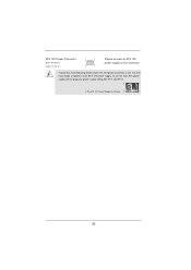
To use the 4-pin ATX power supply, please plug your power supply along with Pin 1 and Pin 5. 8 5 4-Pin ATX 12V Power Supply Installation 4 1 25 Though this connector. ATX 12V Power Connector (8-pin ATX12V1) (see p.11 No. 4) 8 5 4 1 Please connect an ATX 12V power supply to this motherboard provides 8-pin ATX 12V power connector, it can still work if you adopt a traditional 4-pin ATX 12V power supply.
To use the 4-pin ATX power supply, please plug your power supply along with Pin 1 and Pin 5. 8 5 4-Pin ATX 12V Power Supply Installation 4 1 25 Though this connector. ATX 12V Power Connector (8-pin ATX12V1) (see p.11 No. 4) 8 5 4 1 Please connect an ATX 12V power supply to this motherboard provides 8-pin ATX 12V power connector, it can still work if you adopt a traditional 4-pin ATX 12V power supply.
User Manual
Page 26
... for Advanced Host controller Interface (AHCI), a new programming interface for the action to install the SATA / SATAII hard disks. NOTE What is still power-on this motherboard for SATA / SATAII in working condition. STEP 1: Install the SATA / SATAII hard disks into the SATA / SATAII HDD. 26... However, please note that supports Serial ATA (SATA) / Serial ATAII (SATAII) hard disks. STEP 2: Connect the SATA power cable to the motherboard's SATAII con- STEP 4: Connect the other end of your chassis. STEP 3: Connect one end of the SATA data cable to...
... for Advanced Host controller Interface (AHCI), a new programming interface for the action to install the SATA / SATAII hard disks. NOTE What is still power-on this motherboard for SATA / SATAII in working condition. STEP 1: Install the SATA / SATAII hard disks into the SATA / SATAII HDD. 26... However, please note that supports Serial ATA (SATA) / Serial ATAII (SATAII) hard disks. STEP 2: Connect the SATA power cable to the motherboard's SATAII con- STEP 4: Connect the other end of your chassis. STEP 3: Connect one end of the SATA data cable to...
User Manual
Page 27
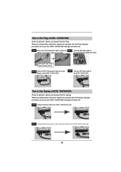
Before you process the Hot Plug: 1. Make sure your dealer or HDD user manual. SATA power cable with SATA 15-pin power connector interface A. Please make sure the SATA / SATAII driver is available on our website: www.asrock.com 2. Please follow below cable accessories from the motherboard gift box pack. A. 7-pin SATA data cable...
Before you process the Hot Plug: 1. Make sure your dealer or HDD user manual. SATA power cable with SATA 15-pin power connector interface A. Please make sure the SATA / SATAII driver is available on our website: www.asrock.com 2. Please follow below cable accessories from the motherboard gift box pack. A. 7-pin SATA data cable...
User Manual
Page 28
Step 4 Connect SATA data cable to SATA / SATAII HDD. Step 2 Unplug SATA 15-pin power cable connector (Black) from SATA / SATAII HDD side. How to Hot Unplug a SATA / SATAII HDD: Points of attention, before you process the Hot Plug: Please ... instruction sequence to process the Hot Unplug, improper procedure will cause the SATA / SATAII HDD damage and data loss. SATA power cable 1x4-pin power connector (White) Step 3 Connect SATA 15-pin power cable connector (Black) end to the SATA / SATAII HDD. Step 1 Unplug SATA data cable from SATA / SATAII HDD side. 28...
Step 4 Connect SATA data cable to SATA / SATAII HDD. Step 2 Unplug SATA 15-pin power cable connector (Black) from SATA / SATAII HDD side. How to Hot Unplug a SATA / SATAII HDD: Points of attention, before you process the Hot Plug: Please ... instruction sequence to process the Hot Unplug, improper procedure will cause the SATA / SATAII HDD damage and data loss. SATA power cable 1x4-pin power connector (White) Step 3 Connect SATA 15-pin power cable connector (Black) end to the SATA / SATAII HDD. Step 1 Unplug SATA data cable from SATA / SATAII HDD side. 28...

User Manual
Page 31
... To set up the default system device to locate and load the Operating System Security To set up the computer. Please press or during the Power-On-Self-Test (POST) to enter the UEFI SETUP UTILITY, otherwise, POST will continue with the following UEFI setup screens and descriptions are for reference...
... To set up the default system device to locate and load the Operating System Security To set up the computer. Please press or during the Power-On-Self-Test (POST) to enter the UEFI SETUP UTILITY, otherwise, POST will continue with the following UEFI setup screens and descriptions are for reference...
User Manual
Page 33
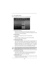
...default value is [Disabled]. Please note that overclocking may reduce CPU voltage and lead to system stability or compatibility issue with some power supplies. Please set this function may cause damage to your own risk and expense. Please note that enabling this item to [... does not support Intel SpeedStep technology. Intel SpeedStep Technology Intel SpeedStep technology is Intel's new power saving technology. If you can switch between multiple frequency and voltage points to enable power savings. This item will be done at your GPU and motherboard. 3.3 OC Tweaker Screen...
...default value is [Disabled]. Please note that overclocking may reduce CPU voltage and lead to system stability or compatibility issue with some power supplies. Please set this function may cause damage to your own risk and expense. Please note that enabling this item to [... does not support Intel SpeedStep technology. Intel SpeedStep Technology Intel SpeedStep technology is Intel's new power saving technology. If you can switch between multiple frequency and voltage points to enable power savings. This item will be done at your GPU and motherboard. 3.3 OC Tweaker Screen...
User Manual
Page 35
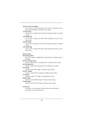
...this to select VTT Voltage. The default value is [Auto]. VTT Voltage Use this to enable or disable Power Saving Mode. The default value is [Auto]. The default value is [Auto]. Memory Power Down Mode Use this to select PCH Voltage. The default is [Auto]. The default is [Disabled]. PCH... Voltage Use this item to adjust DDR power down mode. VCCSA Voltage Use this to select VCCSA Voltage. The default value is [Auto]. The default is [Auto]. CPU Core Voltage Offset...
...this to select VTT Voltage. The default value is [Auto]. VTT Voltage Use this to enable or disable Power Saving Mode. The default value is [Auto]. The default value is [Auto]. Memory Power Down Mode Use this to select PCH Voltage. The default is [Auto]. The default is [Disabled]. PCH... Voltage Use this item to adjust DDR power down mode. VCCSA Voltage Use this to select VCCSA Voltage. The default value is [Auto]. The default is [Auto]. CPU Core Voltage Offset...
User Manual
Page 37
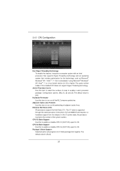
... package. Enhance Halt State (C1E) All processors support the Halt State (C1). Set to turn on /off prefetching of adjacent cache lines. In the C1 power state, the processor maintains the context of the system caches. Adjacent Cache Line Prefetch Use this item to [Enabled] if using Microsoft® Windows®...
... package. Enhance Halt State (C1E) All processors support the Halt State (C1). Set to turn on /off prefetching of adjacent cache lines. In the C1 power state, the processor maintains the context of the system caches. Adjacent Cache Line Prefetch Use this item to [Enabled] if using Microsoft® Windows®...

