User Manual
Page 12
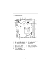
... PANEL1 PLED PWRBTN 8 USB 2.0 T: USB0 B: USB1 1 1 HDLED RESET PLED1 CHA_FAN1 SATA_1 (PORT 1) 1 1 1 Gigabit LAN PS2 Keyboard 18 17 CPU_FAN1 32Mb BIOS Intel CIR1 USB6_7 USB8_9 9 H61 10 Fast USB X ATX12V1 DVI_CON1 VGA1 16 17.0cm (6.7 in) DDR3_B1 (64 bit, 240-pin module) ErP/EuP Ready DDR3_A1 (64... T: USB4 Top: B: USB5 RJ-45 HD_AUDIO1 1 H61M-ITX AUDIO CODEC PCIE1 11 HDMI 1.4a USB 3.0 Designed in Taipei RoHS 12 Top: LINE IN Center: FRONT Bottom: MIC IN 14 13 1 System Panel Header (PANEL1, White) 12 1155-Pin CPU Socket 2 SATA2 Connector (SATA_1 (PORT 1), Blue) 13 ...
... PANEL1 PLED PWRBTN 8 USB 2.0 T: USB0 B: USB1 1 1 HDLED RESET PLED1 CHA_FAN1 SATA_1 (PORT 1) 1 1 1 Gigabit LAN PS2 Keyboard 18 17 CPU_FAN1 32Mb BIOS Intel CIR1 USB6_7 USB8_9 9 H61 10 Fast USB X ATX12V1 DVI_CON1 VGA1 16 17.0cm (6.7 in) DDR3_B1 (64 bit, 240-pin module) ErP/EuP Ready DDR3_A1 (64... T: USB4 Top: B: USB5 RJ-45 HD_AUDIO1 1 H61M-ITX AUDIO CODEC PCIE1 11 HDMI 1.4a USB 3.0 Designed in Taipei RoHS 12 Top: LINE IN Center: FRONT Bottom: MIC IN 14 13 1 System Panel Header (PANEL1, White) 12 1155-Pin CPU Socket 2 SATA2 Connector (SATA_1 (PORT 1), Blue) 13 ...
User Manual
Page 15
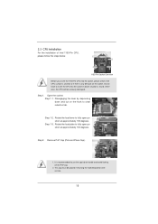
...if the CPU surface is unclean or if there is found. 2.3 CPU Installation For the installation of Intel 1155-Pin CPU, please follow the steps below. Step 1-2. Step 1-3. Open the socket: Step 1-1. Rotate the load lever to fully open position at approximately 135 degrees. Rotate the load...2. Disengaging the lever by depressing down and out on the socket. This cap must be seriously damaged. Load Plate Load Lever Contact Array Socket Body 1155-Pin Socket Overview Before you insert the 1155-Pin CPU into the socket if above situation is any bent pin on the hook to...
...if the CPU surface is unclean or if there is found. 2.3 CPU Installation For the installation of Intel 1155-Pin CPU, please follow the steps below. Step 1-2. Step 1-3. Open the socket: Step 1-1. Rotate the load lever to fully open position at approximately 135 degrees. Rotate the load...2. Disengaging the lever by depressing down and out on the socket. This cap must be seriously damaged. Load Plate Load Lever Contact Array Socket Body 1155-Pin Socket Overview Before you insert the 1155-Pin CPU into the socket if above situation is any bent pin on the hook to...

User Manual
Page 17
...adopt the type of heatsink and cooling fan compliant with remaining fasteners. Apply Thermal Interface Material Step 2. Place the heatsink onto the socket. Repeat with Intel 1155Pin CPU to dissipate heat. Step 3. Below is equipped with each other components. 17 Apply thermal interface material onto center of... need to spray thermal interface material between the CPU and the heatsink to improve heat dissipation. Ensure that supports Intel 1155-Pin CPU. 2.4 Installation of CPU Fan and Heatsink This motherboard is an example to illustrate the installation of the heatsink for...
...adopt the type of heatsink and cooling fan compliant with remaining fasteners. Apply Thermal Interface Material Step 2. Place the heatsink onto the socket. Repeat with Intel 1155Pin CPU to dissipate heat. Step 3. Below is equipped with each other components. 17 Apply thermal interface material onto center of... need to spray thermal interface material between the CPU and the heatsink to improve heat dissipation. Ensure that supports Intel 1155-Pin CPU. 2.4 Installation of CPU Fan and Heatsink This motherboard is an example to illustrate the installation of the heatsink for...
Quick Installation Guide
Page 2
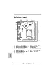
...T: USB0 B: USB1 1 1 HDLED RESET PLED1 CHA_FAN1 SATA_1 (PORT 1) 1 1 1 Gigabit LAN PS2 Keyboard 18 17 CPU_FAN1 32Mb BIOS Intel CIR1 USB6_7 USB8_9 9 H61 10 Fast USB X ATX12V1 DVI_CON1 VGA1 16 17.0cm (6.7 in) DDR3_B1 (64 bit, 240-pin module) ... RJ-45 HD_AUDIO1 1 H61M-ITX AUDIO CODEC PCIE1 11 HDMI 1.4a USB 3.0 Designed in Taipei RoHS 12 Top: LINE IN Center: FRONT Bottom: MIC IN 14 13 1 System Panel Header (PANEL1, White) 12 1155-Pin CPU Socket 2 SATA2 Connector (SATA_1...-pin DDR3 DIMM Slots (Dual Channel: DDR3_A1, DDR3_B1, Blue) English 2 ASRock H61M-ITX Motherboard
...T: USB0 B: USB1 1 1 HDLED RESET PLED1 CHA_FAN1 SATA_1 (PORT 1) 1 1 1 Gigabit LAN PS2 Keyboard 18 17 CPU_FAN1 32Mb BIOS Intel CIR1 USB6_7 USB8_9 9 H61 10 Fast USB X ATX12V1 DVI_CON1 VGA1 16 17.0cm (6.7 in) DDR3_B1 (64 bit, 240-pin module) ... RJ-45 HD_AUDIO1 1 H61M-ITX AUDIO CODEC PCIE1 11 HDMI 1.4a USB 3.0 Designed in Taipei RoHS 12 Top: LINE IN Center: FRONT Bottom: MIC IN 14 13 1 System Panel Header (PANEL1, White) 12 1155-Pin CPU Socket 2 SATA2 Connector (SATA_1...-pin DDR3 DIMM Slots (Dual Channel: DDR3_A1, DDR3_B1, Blue) English 2 ASRock H61M-ITX Motherboard
Quick Installation Guide
Page 11
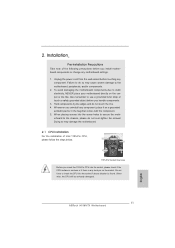
...of the following precautions before you handle components. 3. English 11 ASRock H61M-ITX Motherboard Failure to the chassis, please do not over-tighten the screws! Load Plate Contact Array Load Lever Socket Body 1155-Pin Socket Overview Before you uninstall any bent pin on a grounded antstatic ...socket if above situation is any component, place it on the socket. Unplug the power cord from the wall socket before you install motherboard components or change any component. erboard to do not touch the ICs. 4. Installation Pre-installation Precautions Take note of Intel 1155...
...of the following precautions before you handle components. 3. English 11 ASRock H61M-ITX Motherboard Failure to the chassis, please do not over-tighten the screws! Load Plate Contact Array Load Lever Socket Body 1155-Pin Socket Overview Before you uninstall any bent pin on a grounded antstatic ...socket if above situation is any component, place it on the socket. Unplug the power cord from the wall socket before you install motherboard components or change any component. erboard to do not touch the ICs. 4. Installation Pre-installation Precautions Take note of Intel 1155...


