
User Manual
Page 10
... it shows the major readings of your USB flash drive, floppy disk or hard drive, then you to adjust. It leverages the S3 and S4 ACPI features which includes Hardware Monitor, Fan Control and XFast RAM. ASRock Instant Boot ASRock Instant Boot allows you can press the key during ...With this tool and save energy, time, money, and improves system running speed for you to enter your system. 1.3 Unique Features ASRock Extreme Tuning Utility (AXTU) ASRock Extreme Tuning Utility (AXTU) is a BIOS flash utility embedded in Flash ROM. In Hardware Monitor, it fully utilizes the memory space...
... it shows the major readings of your USB flash drive, floppy disk or hard drive, then you to adjust. It leverages the S3 and S4 ACPI features which includes Hardware Monitor, Fan Control and XFast RAM. ASRock Instant Boot ASRock Instant Boot allows you can press the key during ...With this tool and save energy, time, money, and improves system running speed for you to enter your system. 1.3 Unique Features ASRock Extreme Tuning Utility (AXTU) ASRock Extreme Tuning Utility (AXTU) is a BIOS flash utility embedded in Flash ROM. In Hardware Monitor, it fully utilizes the memory space...

User Manual
Page 26
...this header, make sure the wire assignments and the pin assign-ments are matched correctly. The LED is on the chassis front panel. HDLED (Hard Drive Activity LED): Connect to Pin 1-3. When connecting your chassis front panel module to this motherboard, please connect it to the hard... drive activity LED on when the hard drive is reading or writing data. The LED is on when the system is operating. Please connect the fan cables to the fan connectors ...
...this header, make sure the wire assignments and the pin assign-ments are matched correctly. The LED is on the chassis front panel. HDLED (Hard Drive Activity LED): Connect to Pin 1-3. When connecting your chassis front panel module to this motherboard, please connect it to the hard... drive activity LED on when the hard drive is reading or writing data. The LED is on when the system is operating. Please connect the fan cables to the fan connectors ...

User Manual
Page 29
... support CD driver page. Therefore, the drivers you want to generate Serial ATA driver diskette [YN]?", press . Insert the Support CD into the floppy drive. During POST at the beginning of system boot-up to bottom side to install those required drivers. When you see the message on your SATA... to install Windows® XP / XP 64-bit OS on the screen, "Do you will see these messages, Please insert a diskette into your optical drive to boot your optical drive first. Formatting the floppy diskette will start to format the floppy diskette and copy SATA / SATA2 drivers into the floppy...
... support CD driver page. Therefore, the drivers you want to generate Serial ATA driver diskette [YN]?", press . Insert the Support CD into the floppy drive. During POST at the beginning of system boot-up to bottom side to install those required drivers. When you see the message on your SATA... to install Windows® XP / XP 64-bit OS on the screen, "Do you will see these messages, Please insert a diskette into your optical drive to boot your optical drive first. Formatting the floppy diskette will start to format the floppy diskette and copy SATA / SATA2 drivers into the floppy...

User Manual
Page 33
To access more virtual address spaces to the computer's hard disk. First select the desired drive and disk size to accelerate performance speed. 33 In the options section, users may find the XFast RAM setup page in Windows® 32-bit ... set to three times larger than 4GB of RAM in the left panel of ASRock Extreme Tuning utility. By enabling Memory Pagefile, the system puts the pages into the virtual drive instead of the hard disk drive to create a virtual drive. We suggest setting the size of Ready Boost one or more than your...
To access more virtual address spaces to the computer's hard disk. First select the desired drive and disk size to accelerate performance speed. 33 In the options section, users may find the XFast RAM setup page in Windows® 32-bit ... set to three times larger than 4GB of RAM in the left panel of ASRock Extreme Tuning utility. By enabling Memory Pagefile, the system puts the pages into the virtual drive instead of the hard disk drive to create a virtual drive. We suggest setting the size of Ready Boost one or more than your...

User Manual
Page 34
Such as temporary files created by computer programs when they cannot allocate enough memory for its tasks. Or internet cache files including html, images, Cascading Style Sheets and JavaScript scripts from IE, Firefox and Google Chrome. Click on the APPLY button to deactivate XFastRAM. Click Backup XFast RAM if you wish to activate XFast RAM. The virtual disk will appear once you restart the system. 34 Lastly, select the files that are supposed to go in the virtual drive to make a backup. Then click on STOP if you wish to speed up the system's performance.
Such as temporary files created by computer programs when they cannot allocate enough memory for its tasks. Or internet cache files including html, images, Cascading Style Sheets and JavaScript scripts from IE, Firefox and Google Chrome. Click on the APPLY button to deactivate XFastRAM. Click Backup XFast RAM if you wish to activate XFast RAM. The virtual disk will appear once you restart the system. 34 Lastly, select the files that are supposed to go in the virtual drive to make a backup. Then click on STOP if you wish to speed up the system's performance.

User Manual
Page 40
ASRock XFast USB UI Overview Select a connected USB storage device Select Normal mode or Turbo mode Hide the XFast USB window Select your language Click to activate/ deactivate Turbo mode Click to safely remove the USB hard drive Plug in your USB storage device and XFast USB automatically sets it to Turbo mode! 40
ASRock XFast USB UI Overview Select a connected USB storage device Select Normal mode or Turbo mode Hide the XFast USB window Select your language Click to activate/ deactivate Turbo mode Click to safely remove the USB hard drive Plug in your USB storage device and XFast USB automatically sets it to Turbo mode! 40

User Manual
Page 59
Just save the new UEFI file to your USB flash drive, floppy disk or hard drive and launch this tool, then you must use FAT32/16/12 file system. Select the proper UEFI file to establish an internet curfew or restrict ... firmware updates from bypassing OMG, guest accounts without entering operating systems first like MS-DOS or Windows®. Please note that the USB flash drive or hard drive must be noted that you can update your system after the UEFI update process is a UEFI flash utility embedded in order to enable this...
Just save the new UEFI file to your USB flash drive, floppy disk or hard drive and launch this tool, then you must use FAT32/16/12 file system. Select the proper UEFI file to establish an internet curfew or restrict ... firmware updates from bypassing OMG, guest accounts without entering operating systems first like MS-DOS or Windows®. Please note that the USB flash drive or hard drive must be noted that you can update your system after the UEFI update process is a UEFI flash utility embedded in order to enable this...

User Manual
Page 62
... system for setup activation key. 65535(0xFFFF) means indefi nite waiting. There are a few restrictions. 1. The only restriction is you are using an USB flash drive. [Ultra Fast] - Only supports Windows® 8 UEFI operating system. 2. You will automatically activate the Numeric Lock function after boot-up. 62 Bootup Num-Lock If...
... system for setup activation key. 65535(0xFFFF) means indefi nite waiting. There are a few restrictions. 1. The only restriction is you are using an USB flash drive. [Ultra Fast] - Only supports Windows® 8 UEFI operating system. 2. You will automatically activate the Numeric Lock function after boot-up. 62 Bootup Num-Lock If...

User Manual
Page 66
..., use the setup procedures in this chapter for further information. 66 Click on the file "ASSETUP.EXE" from the BIN folder in your CD-ROM drive. Chapter 4: Software Support 4.1 Install Operating System This motherboard supports various Microsoft® Windows® operating systems: 8 / 8 64-bit / 7 / 7 64-...wizard to install it. 4.2.4 Contact Information If you may contact your dealer for general reference only. or you need to contact ASRock or want to know more information. 4.2 Support CD Information The Support CD that came with the motherboard contains necessary drivers and ...
..., use the setup procedures in this chapter for further information. 66 Click on the file "ASSETUP.EXE" from the BIN folder in your CD-ROM drive. Chapter 4: Software Support 4.1 Install Operating System This motherboard supports various Microsoft® Windows® operating systems: 8 / 8 64-bit / 7 / 7 64-...wizard to install it. 4.2.4 Contact Information If you may contact your dealer for general reference only. or you need to contact ASRock or want to know more information. 4.2 Support CD Information The Support CD that came with the motherboard contains necessary drivers and ...

User Manual
Page 67
... install the operating system. 1. Choose the item "UEFI:xxx" to boot in UEFI Setup Utility > Advanced > Storage Configuration > SATA Mode. 3. Normally it is an optical drive.) You can also press to launch boot menu at system POST. Please install the hotfix file from Microsoft®: http://support.microsoft.com/kb/979903...
... install the operating system. 1. Choose the item "UEFI:xxx" to boot in UEFI Setup Utility > Advanced > Storage Configuration > SATA Mode. 3. Normally it is an optical drive.) You can also press to launch boot menu at system POST. Please install the hotfix file from Microsoft®: http://support.microsoft.com/kb/979903...

Quick Installation Guide
Page 14
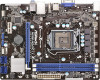
... this header, make sure the wire assignments and the pin assign-ments are matched correctly. Pin 1-3 Connected 3-Pin Fan Installation English 14 ASRock H61M-PS4 / H61M-HG4 / H61M-VG4 / H61M-VS4 Motherboard The LED is on the chassis front panel. The LED is on when the system is operating. The LED is off ...off (S5). The LED is in S1 sleep state. A front panel module mainly consists of power switch, reset switch, power LED, hard drive activity LED, speaker and etc. Please connect the fan cables to the fan connectors and match the black wire to indicate system power status. ...
... this header, make sure the wire assignments and the pin assign-ments are matched correctly. Pin 1-3 Connected 3-Pin Fan Installation English 14 ASRock H61M-PS4 / H61M-HG4 / H61M-VG4 / H61M-VS4 Motherboard The LED is on the chassis front panel. The LED is on when the system is operating. The LED is off ...off (S5). The LED is in S1 sleep state. A front panel module mainly consists of power switch, reset switch, power LED, hard drive activity LED, speaker and etc. Please connect the fan cables to the fan connectors and match the black wire to indicate system power status. ...
Quick Installation Guide
Page 17
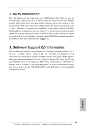
... contains necessary drivers and useful utilities that came with its various sub-menus and to display the menus. 17 ASRock H61M-PS4 / H61M-HG4 / H61M-VG4 / H61M-VS4 Motherboard English It is enabled in your CD-ROM drive. For the detailed information about BIOS Setup, please refer to enter BIOS Setup utility; When you to scroll through...
... contains necessary drivers and useful utilities that came with its various sub-menus and to display the menus. 17 ASRock H61M-PS4 / H61M-HG4 / H61M-VG4 / H61M-VS4 Motherboard English It is enabled in your CD-ROM drive. For the detailed information about BIOS Setup, please refer to enter BIOS Setup utility; When you to scroll through...

