
User Manual
Page 3
... Precautions 17 2.3 CPU Installation 18 2.4 Installation of Heatsink and CPU fan 20 2.5 Installation of Memory Modules (DIMM 21 2.6 Expansion Slots (PCI Express Slots 22 2.7 Jumpers Setup 23 2.8 Onboard Headers and Connectors 24 2.9 Driver Installation Guide 29 2.10 Installing Windows® 8 / 8 64-bit / 7 / 7 64-bit / VistaTM / VistaTM 64... RAID Functions 29 2.10.2 Installing Windows® 8 / 8 64-bit / 7 / 7 64-bit / VistaTM / VistaTM 64-bit Without RAID Functions. 30 2.11 ASRock XFast 555 31 2.11.1 ASRock XFast RAM 32 2.11.2 ASRock XFast LAN 35 2.11.3 ASRock XFast USB 39 3
... Precautions 17 2.3 CPU Installation 18 2.4 Installation of Heatsink and CPU fan 20 2.5 Installation of Memory Modules (DIMM 21 2.6 Expansion Slots (PCI Express Slots 22 2.7 Jumpers Setup 23 2.8 Onboard Headers and Connectors 24 2.9 Driver Installation Guide 29 2.10 Installing Windows® 8 / 8 64-bit / 7 / 7 64-bit / VistaTM / VistaTM 64... RAID Functions 29 2.10.2 Installing Windows® 8 / 8 64-bit / 7 / 7 64-bit / VistaTM / VistaTM 64-bit Without RAID Functions. 30 2.11 ASRock XFast 555 31 2.11.1 ASRock XFast RAM 32 2.11.2 ASRock XFast LAN 35 2.11.3 ASRock XFast USB 39 3

User Manual
Page 4
3 UEFI SETUP UTILITY 41 3.1 Introduction 41 3.1.1 UEFI Menu Bar 41 3.1.2 Navigation Keys 42 3.2 Main Screen 42 3.3 OC Tweaker Screen 44 3.4 Advanced Screen 48 3.4.1 CPU Configuration 49 3.4.2 North ...
3 UEFI SETUP UTILITY 41 3.1 Introduction 41 3.1.1 UEFI Menu Bar 41 3.1.2 Navigation Keys 42 3.2 Main Screen 42 3.3 OC Tweaker Screen 44 3.4 Advanced Screen 48 3.4.1 CPU Configuration 49 3.4.2 North ...

User Manual
Page 5
... Factor) ASRock H61M-PS4 / H61M-HG4 / H61M-VG4 / H61M-VS4 Quick Installation Guide ASRock H61M-PS4 / H61M-HG4 / H61M-VG4 / H61M-VS4 Support CD 2 x Serial ATA (SATA) Data Cables (Optional) 1 x I/O Panel Shield ASRock Reminds You... In this manual occur, the updated version will be available on ASRock website as well. It delivers excellent performance with robust design conforming to ASRock's commitment to BIOS setup and information...
... Factor) ASRock H61M-PS4 / H61M-HG4 / H61M-VG4 / H61M-VS4 Quick Installation Guide ASRock H61M-PS4 / H61M-HG4 / H61M-VG4 / H61M-VS4 Support CD 2 x Serial ATA (SATA) Data Cables (Optional) 1 x I/O Panel Shield ASRock Reminds You... In this manual occur, the updated version will be available on ASRock website as well. It delivers excellent performance with robust design conforming to ASRock's commitment to BIOS setup and information...

User Manual
Page 10
... and XFast RAM. Please be used under Windows® OS 32-bit CPU. 1.3 Unique Features ASRock Extreme Tuning Utility (AXTU) ASRock Extreme Tuning Utility (AXTU) is a BIOS flash utility embedded in a few seconds. With this tool... BIOS only in a few clicks without entering operating systems first like MSDOS or Windows®. ASRock Instant Flash ASRock Instant Flash is an all-in-one tool to shorten boot up time. In XFast RAM...specific timing during the POST or the key to enter into the BIOS setup menu to your USB flash drive, floppy disk or hard drive, then you to save the...
... and XFast RAM. Please be used under Windows® OS 32-bit CPU. 1.3 Unique Features ASRock Extreme Tuning Utility (AXTU) ASRock Extreme Tuning Utility (AXTU) is a BIOS flash utility embedded in a few seconds. With this tool... BIOS only in a few clicks without entering operating systems first like MSDOS or Windows®. ASRock Instant Flash ASRock Instant Flash is an all-in-one tool to shorten boot up time. In XFast RAM...specific timing during the POST or the key to enter into the BIOS setup menu to your USB flash drive, floppy disk or hard drive, then you to save the...

User Manual
Page 13
... simply enable this , Good night LED will automatically switch off when system is designed for those requiring frequent UEFI access. ASRock Combo Cooler Option (C.C.O.) Combo Cooler Option (C.C.O.) provides the flexible option to access the UEFI directly in BIOS, the Power ...ASRock Good Night LED technology can be noticed that not all the 775 and 1156 CPU Fan can offer you a better environment by extinguishing the unessential LED. By enabling Good Night LED in the very beginning. The lightning boot up experience. Please be used. It allows users to access the UEFI setup...
... simply enable this , Good night LED will automatically switch off when system is designed for those requiring frequent UEFI access. ASRock Combo Cooler Option (C.C.O.) Combo Cooler Option (C.C.O.) provides the flexible option to access the UEFI directly in BIOS, the Power ...ASRock Good Night LED technology can be noticed that not all the 775 and 1156 CPU Fan can offer you a better environment by extinguishing the unessential LED. By enabling Good Night LED in the very beginning. The lightning boot up experience. Please be used. It allows users to access the UEFI setup...

User Manual
Page 23
2.7 Jumpers Setup The illustration shows how jumpers are "Short" when jumper cap is placed on pins, the jumper is... password, date, time and user default profile will be detected. The illustration shows a 3-pin jumper whose pin1 and pin2 are setup. When the jumper cap is placed on CLRCMOS1 for 15 seconds, use a jumper cap to clear the data in CMOS. If... no jumper cap is placed on these 2 pins. If you need to default setup, please turn off the computer and unplug the power cord from the power supply. If you clear the CMOS, the case ...
2.7 Jumpers Setup The illustration shows how jumpers are "Short" when jumper cap is placed on pins, the jumper is... password, date, time and user default profile will be detected. The illustration shows a 3-pin jumper whose pin1 and pin2 are setup. When the jumper cap is placed on CLRCMOS1 for 15 seconds, use a jumper cap to clear the data in CMOS. If... no jumper cap is placed on these 2 pins. If you need to default setup, please turn off the computer and unplug the power cord from the power supply. If you clear the CMOS, the case ...

User Manual
Page 29
... functions, please follow the order from up , press key, and then a window for boot devices selection appears. The system will start to [AHCI]. Enter UEFI SETUP UTILITY Advanced screen Storage Configuration. Set the option "SATA Mode Selection" to format the floppy diskette and copy SATA / SATA2 drivers into your optical drive...
... functions, please follow the order from up , press key, and then a window for boot devices selection appears. The system will start to [AHCI]. Enter UEFI SETUP UTILITY Advanced screen Storage Configuration. Set the option "SATA Mode Selection" to format the floppy diskette and copy SATA / SATA2 drivers into your optical drive...

User Manual
Page 30
... the option "SATA Mode Selection" to [IDE]. When prompted, insert the SATA / SATA2 driver diskette containing the Intel® AHCI driver. B. Enter UEFI SETUP UTILITY Advanced screen Storage Configuration. B. Set the option "SATA Mode Selection" to [AHCI]. STEP 2: Install Windows® 8 / 8 64-bit / 7... please follow below steps. STEP 2: Install Windows® XP / XP 64-bit OS on your system. 30 B. A. Enter UEFI SETUP UTILITY Advanced screen Storage Configuration. Using SATA / SATA2 HDDs without NCQ function STEP 1: Set up UEFI. After making a SATA / SATA2 ...
... the option "SATA Mode Selection" to [IDE]. When prompted, insert the SATA / SATA2 driver diskette containing the Intel® AHCI driver. B. Enter UEFI SETUP UTILITY Advanced screen Storage Configuration. B. Set the option "SATA Mode Selection" to [AHCI]. STEP 2: Install Windows® 8 / 8 64-bit / 7... please follow below steps. STEP 2: Install Windows® XP / XP 64-bit OS on your system. 30 B. A. Enter UEFI SETUP UTILITY Advanced screen Storage Configuration. Using SATA / SATA2 HDDs without NCQ function STEP 1: Set up UEFI. After making a SATA / SATA2 ...

User Manual
Page 33
...-bit OS. First select the desired drive and disk size to accelerate performance speed. 33 In the options section, users may find the XFast RAM setup page in Windows® 32-bit OS, please leave PAE mode set to ON. To access more virtual address spaces to three times larger than... 4GB of RAM in the left panel of ASRock Extreme Tuning utility. By enabling Memory Pagefile, the system puts the pages into the virtual drive instead of the hard disk drive to create a virtual...
...-bit OS. First select the desired drive and disk size to accelerate performance speed. 33 In the options section, users may find the XFast RAM setup page in Windows® 32-bit OS, please leave PAE mode set to ON. To access more virtual address spaces to three times larger than... 4GB of RAM in the left panel of ASRock Extreme Tuning utility. By enabling Memory Pagefile, the system puts the pages into the virtual drive instead of the hard disk drive to create a virtual...

User Manual
Page 41
... button on the menu bar, and then press to get into the sub screen. The UEFI chip on . If you wish to enter the UEFI SETUP UTILITY after POST, restart the system by pressing + + , or by turning the system off and then back on the motherboard stores the UEFI... with its test routines. You may not exactly match what you start up the security features Exit To exit the current screen or the UEFI SETUP UTILITY Use < > key or < > key to choose among the selections on the system chassis. Because the UEFI software is constantly being updated, the following selections...
... button on the menu bar, and then press to get into the sub screen. The UEFI chip on . If you wish to enter the UEFI SETUP UTILITY after POST, restart the system by pressing + + , or by turning the system off and then back on the motherboard stores the UEFI... with its test routines. You may not exactly match what you start up the security features Exit To exit the current screen or the UEFI SETUP UTILITY Use < > key or < > key to choose among the selections on the system chassis. Because the UEFI software is constantly being updated, the following selections...

User Manual
Page 42
H61M-PS4 42 To change option for the selected items Switch to next function To bring up or down to select items + / - 3.1.2 Navigation Keys Please check the following table for all the settings Save changes and exit the UEFI SETUP UTILITY Print screen Jump to the Exit Screen or exit the ...current screen 3.2 Main Screen When you enter the UEFI SETUP UTILITY, the Main screen will appear and display the system overview. Navigation Key(s) Function Description / Moves cursor left or right to select Screens / ...
H61M-PS4 42 To change option for the selected items Switch to next function To bring up or down to select items + / - 3.1.2 Navigation Keys Please check the following table for all the settings Save changes and exit the UEFI SETUP UTILITY Print screen Jump to the Exit Screen or exit the ...current screen 3.2 Main Screen When you enter the UEFI SETUP UTILITY, the Main screen will appear and display the system overview. Navigation Key(s) Function Description / Moves cursor left or right to select Screens / ...

User Manual
Page 58
...If you enable Fast Boot option. The default value is [Enabled]. 3.4.9 USB Configuration USB 2.0 Controller Use this option to enter OS. [UEFI Setup Only] - CSM Please disable CSM when you have USB compatibility issue, it is recommended to select [Disabled] to select legacy support for USB ...devices. Enables legacy support if USB devices are four configuration options: [Enabled], [Auto], [Disabled] and [UEFI Setup Only]. Legacy USB Support Use this item to below descriptions for legacy USB. [Auto] - Please refer to enable or disable the use of...
...If you enable Fast Boot option. The default value is [Enabled]. 3.4.9 USB Configuration USB 2.0 Controller Use this option to enter OS. [UEFI Setup Only] - CSM Please disable CSM when you have USB compatibility issue, it is recommended to select [Disabled] to select legacy support for USB ...devices. Enables legacy support if USB devices are four configuration options: [Enabled], [Auto], [Disabled] and [UEFI Setup Only]. Legacy USB Support Use this item to below descriptions for legacy USB. [Auto] - Please refer to enable or disable the use of...

User Manual
Page 62
... 62 Disable Fast Boot. [Fast] - There are three configuration options: [Disabled], [Fast] and [Ultra Fast]. Fast Boot Fast Boot minimizes your system for setup activation key. 65535(0xFFFF) means indefi nite waiting. Please refer to enable or disable the Boot From Onboard LAN feature. You will not be able... to enter BIOS Setup (Clear CMOS or run utility in order to enter BIOS Setup). 3. There are a few restrictions. 1. The default value is [Disabled]. If you may not boot by using an...
... 62 Disable Fast Boot. [Fast] - There are three configuration options: [Disabled], [Fast] and [Ultra Fast]. Fast Boot Fast Boot minimizes your system for setup activation key. 65535(0xFFFF) means indefi nite waiting. Please refer to enable or disable the Boot From Onboard LAN feature. You will not be able... to enter BIOS Setup (Clear CMOS or run utility in order to enter BIOS Setup). 3. There are a few restrictions. 1. The default value is [Disabled]. If you may not boot by using an...

User Manual
Page 65
...changes. will pop-out. Select [Yes] to save the changes and exit the UEFI SETUP UTILITY. Discard Changes When you select this option, the following message "Discard changes and exit setup?" Load UEFI Defaults Load UEFI default values for this option, the following message "Discard changes...?" Discard Changes and Exit When you select this option, the following message "Save configuration changes and exit setup?" F9 key can be used for all changes. will pop-out. Launch EFI Shell from one of the available filesystem devices. 65 ...
...changes. will pop-out. Select [Yes] to save the changes and exit the UEFI SETUP UTILITY. Discard Changes When you select this option, the following message "Discard changes and exit setup?" Load UEFI Defaults Load UEFI default values for this option, the following message "Discard changes...?" Discard Changes and Exit When you select this option, the following message "Save configuration changes and exit setup?" F9 key can be used for all changes. will pop-out. Launch EFI Shell from one of the available filesystem devices. 65 ...

User Manual
Page 66
... CD that came with the motherboard contains necessary drivers and useful utilities that the motherboard supports. Refer to visit ASRock's website at http://www.asrock.com; If the Main Menu did not appear automatically, locate and double click on a specific item then follow... Drivers Menu shows the available devices drivers if the system detects installed devices. Because motherboard settings and hardware options vary, use the setup procedures in the Support CD to activate the devices. 4.2.3 Utilities Menu The Utilities Menu shows the applications software that enhance the motherboard...
... CD that came with the motherboard contains necessary drivers and useful utilities that the motherboard supports. Refer to visit ASRock's website at http://www.asrock.com; If the Main Menu did not appear automatically, locate and double click on a specific item then follow... Drivers Menu shows the available devices drivers if the system detects installed devices. Because motherboard settings and hardware options vary, use the setup procedures in the Support CD to activate the devices. 4.2.3 Utilities Menu The Utilities Menu shows the applications software that enhance the motherboard...

User Manual
Page 67
Start Windows® installation. 5. Set AHCI Mode in UEFI Setup Utility > Boot > Boot Option #1. ("xxx" is the device which contains your Windows® installation files. If you install Windows® 7 64-bit OS, OS will ...® 7 64-bit or Windows® 8 64-bit. 2. Please make sure to install the operating system. 1. Choose the item "UEFI:xxx" to boot in UEFI Setup Utility > Advanced > Storage Configuration > SATA Mode. 3. Please install the hotfix file from Microsoft®: http://support.microsoft.com/kb/979903 67 Installing OS on a HDD...
Start Windows® installation. 5. Set AHCI Mode in UEFI Setup Utility > Boot > Boot Option #1. ("xxx" is the device which contains your Windows® installation files. If you install Windows® 7 64-bit OS, OS will ...® 7 64-bit or Windows® 8 64-bit. 2. Please make sure to install the operating system. 1. Choose the item "UEFI:xxx" to boot in UEFI Setup Utility > Advanced > Storage Configuration > SATA Mode. 3. Please install the hotfix file from Microsoft®: http://support.microsoft.com/kb/979903 67 Installing OS on a HDD...

Quick Installation Guide
Page 5
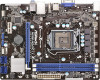
... of the motherboard and step-bystep installation guide. www.asrock.com/support/index.asp 1.1 Package Contents ASRock H61M-PS4 / H61M-HG4 / H61M-VG4 / H61M-VS4 Motherboard (Micro ATX Form Factor) ASRock H61M-PS4 / H61M-HG4 / H61M-VG4 / H61M-VS4 Quick Installation Guide ASRock H61M-PS4 / H61M-HG4 / H61M-VG4 / H61M-VS4 Support CD 2 x Serial ATA (SATA) Data...VistaTM / VistaTM 64-bit, it is recommended to set the BIOS option in our support CD for details. 5 ASRock H61M-PS4 / H61M-HG4 / H61M-VG4 / H61M-VS4 Motherboard English For the BIOS setup, please refer to change without further notice.
... of the motherboard and step-bystep installation guide. www.asrock.com/support/index.asp 1.1 Package Contents ASRock H61M-PS4 / H61M-HG4 / H61M-VG4 / H61M-VS4 Motherboard (Micro ATX Form Factor) ASRock H61M-PS4 / H61M-HG4 / H61M-VG4 / H61M-VS4 Quick Installation Guide ASRock H61M-PS4 / H61M-HG4 / H61M-VG4 / H61M-VS4 Support CD 2 x Serial ATA (SATA) Data...VistaTM / VistaTM 64-bit, it is recommended to set the BIOS option in our support CD for details. 5 ASRock H61M-PS4 / H61M-HG4 / H61M-VG4 / H61M-VS4 Motherboard English For the BIOS setup, please refer to change without further notice.

Quick Installation Guide
Page 10
... DUMMY 1 GND P+ PUSB_PWR 1 DUMMY REST# GND HDLEDHDLED+ System Panel Header USB 2.0 Header 10 ASRock H61M-PS4 / H61M-HG4 / H61M-VG4 / H61M-VS4 Motherboard If you to recognize the crucial headers more information about the usage of these headers, please refer to "Jumpers Setup" and "Onboard Headers and Connectors" for the pin definition of onboard headers. 1.3 Pin Header...
... DUMMY 1 GND P+ PUSB_PWR 1 DUMMY REST# GND HDLEDHDLED+ System Panel Header USB 2.0 Header 10 ASRock H61M-PS4 / H61M-HG4 / H61M-VG4 / H61M-VS4 Motherboard If you to recognize the crucial headers more information about the usage of these headers, please refer to "Jumpers Setup" and "Onboard Headers and Connectors" for the pin definition of onboard headers. 1.3 Pin Header...

Quick Installation Guide
Page 11
...on pins, the jumper is placed on these 2 pins. The illustration shows a 3-pin jumper whose pin1 and pin2 are setup. To clear and reset the system parameters to short pin2 and pin3 on pins, the jumper is removed. Please be noted... will be detected. If no jumper cap is placed on CLRCMOS1 for 15 seconds, use a jumper cap to default setup, please turn off the computer and unplug the power cord from the power supply. If you need to clear the ... only if the CMOS battery is "Open". If you update the BIOS. English 11 ASRock H61M-PS4 / H61M-HG4 / H61M-VG4 / H61M-VS4 Motherboard
...on pins, the jumper is placed on these 2 pins. The illustration shows a 3-pin jumper whose pin1 and pin2 are setup. To clear and reset the system parameters to short pin2 and pin3 on pins, the jumper is removed. Please be noted... will be detected. If no jumper cap is placed on CLRCMOS1 for 15 seconds, use a jumper cap to default setup, please turn off the computer and unplug the power cord from the power supply. If you need to clear the ... only if the CMOS battery is "Open". If you update the BIOS. English 11 ASRock H61M-PS4 / H61M-HG4 / H61M-VG4 / H61M-VS4 Motherboard
Quick Installation Guide
Page 17
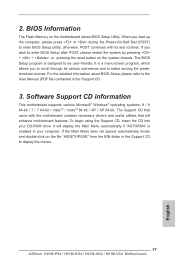
... display the Main Menu automatically if "AUTORUN" is a menu-driven program, which allows you to display the menus. 17 ASRock H61M-PS4 / H61M-HG4 / H61M-VG4 / H61M-VS4 Motherboard English When you wish to enter BIOS Setup utility; otherwise, POST continues with the motherboard contains necessary drivers and useful utilities that came with its various sub-menus...
... display the Main Menu automatically if "AUTORUN" is a menu-driven program, which allows you to display the menus. 17 ASRock H61M-PS4 / H61M-HG4 / H61M-VG4 / H61M-VS4 Motherboard English When you wish to enter BIOS Setup utility; otherwise, POST continues with the motherboard contains necessary drivers and useful utilities that came with its various sub-menus...


