
User Manual
Page 10
... CPU fan on the motherboard functions properly and unplug the power cord, then plug it back again. According to adopt three different CPU cooler types, Socket LGA 775, LGA 1155 and LGA 1156. Please be noticed that not all the 775 and 1156 CPU Fan can be under 100 mA current...
... CPU fan on the motherboard functions properly and unplug the power cord, then plug it back again. According to adopt three different CPU cooler types, Socket LGA 775, LGA 1155 and LGA 1156. Please be noticed that not all the 775 and 1156 CPU Fan can be under 100 mA current...
User Manual
Page 11
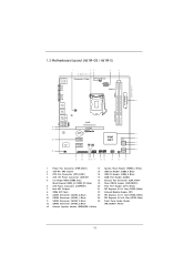
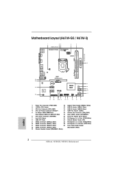
1.3 Motherboard Layout (H61M-GS / H61M-S) PS2 Mouse PS2 Keyboard 1 23 4 5 19.8cm (7.8 in) Designed in Taipei ErP/EuP Ready CPU_FAN1 ATX12V1 DX10.1 VGA1 24.4cm (9.6 in) DDR3 ATXPWR1 DDR3_B1 (64 ... Channel 6 7 8 9 10 11 21 20 1918 17 16 15 14 13 12 1 Power Fan Connector (PWR_FAN1) 14 System Panel Header (PANEL1, White) 2 1155-Pin CPU Socket 15 USB 2.0 Header (USB6_7, Blue) 3 CPU Fan Connector (CPU_FAN1) 16 USB 2.0 Header (USB8_9, Blue) 4 ATX 12V Power Connector (ATX12V1 17 COM Port Header (COM1) 5 2 x 240...
1.3 Motherboard Layout (H61M-GS / H61M-S) PS2 Mouse PS2 Keyboard 1 23 4 5 19.8cm (7.8 in) Designed in Taipei ErP/EuP Ready CPU_FAN1 ATX12V1 DX10.1 VGA1 24.4cm (9.6 in) DDR3 ATXPWR1 DDR3_B1 (64 ... Channel 6 7 8 9 10 11 21 20 1918 17 16 15 14 13 12 1 Power Fan Connector (PWR_FAN1) 14 System Panel Header (PANEL1, White) 2 1155-Pin CPU Socket 15 USB 2.0 Header (USB6_7, Blue) 3 CPU Fan Connector (CPU_FAN1) 16 USB 2.0 Header (USB8_9, Blue) 4 ATX 12V Power Connector (ATX12V1 17 COM Port Header (COM1) 5 2 x 240...

User Manual
Page 14
... physical injuries to you install motherboard components or change any component, ensure that comes with the component. Chapter 2: Installation This is detached from the wall socket before touching any component, place it .
... physical injuries to you install motherboard components or change any component, ensure that comes with the component. Chapter 2: Installation This is detached from the wall socket before touching any component, place it .

User Manual
Page 15
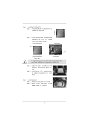
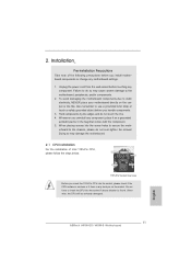
... seriously damaged. Remove PnP Cap (Pick and Place Cap). 1. Load Plate Load Lever Contact Array Socket Body 1155-Pin Socket Overview Before you insert the 1155-Pin CPU into the socket if above situation is any bent pin on the hook to fully open position at approximately 135 degrees... load lever to clear retention tab. Step 1-2. Disengaging the lever by depressing down and out on the socket. Open the socket: Step 1-1. Step 1-3. Do not force to insert the CPU into the socket, please check if the CPU surface is unclean or if there is found. 2.3 CPU Installation For the...
... seriously damaged. Remove PnP Cap (Pick and Place Cap). 1. Load Plate Load Lever Contact Array Socket Body 1155-Pin Socket Overview Before you insert the 1155-Pin CPU into the socket if above situation is any bent pin on the hook to fully open position at approximately 135 degrees... load lever to clear retention tab. Step 1-2. Disengaging the lever by depressing down and out on the socket. Open the socket: Step 1-1. Step 1-3. Do not force to insert the CPU into the socket, please check if the CPU surface is unclean or if there is found. 2.3 CPU Installation For the...
User Manual
Page 16
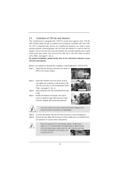
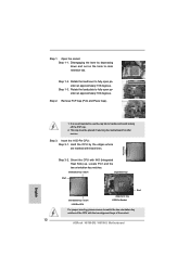
... with black line. Step 3-4. Step 4-2. Carefully place the CPU into the socket by the edge where is within the socket and properly mated to match the two orientation key notches of the socket. Close the socket: Step 4-1. Hold the CPU by using a purely vertical motion. orientation key... notch alignment key Pin1 Pin1 orientation key notch 1155-Pin CPU alignment key 1155-Pin Socket For proper inserting, please ensure to the orient keys. Insert the 1155-Pin CPU: Step 3-1. black line Step 3-2. Orient the CPU with...
... with black line. Step 3-4. Step 4-2. Carefully place the CPU into the socket by the edge where is within the socket and properly mated to match the two orientation key notches of the socket. Close the socket: Step 4-1. Hold the CPU by using a purely vertical motion. orientation key... notch alignment key Pin1 Pin1 orientation key notch 1155-Pin CPU alignment key 1155-Pin Socket For proper inserting, please ensure to the orient keys. Insert the 1155-Pin CPU: Step 3-1. black line Step 3-2. Orient the CPU with...
User Manual
Page 17
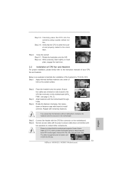
...cannot be noticed that this motherboard supports Combo Cooler Option (C.C.O.), which provides the flexible option to adopt three different CPU cooler types, Socket LGA 775, LGA 1155 and LGA 1156. Step 5. Connect fan header with thumb to install and lock. The white throughholes are oriented on...see page 11, No. 3). Then connect the CPU fan to dissipate heat. Please be secured on the motherboard. Place the heatsink onto the socket. Repeat with fan operation or contact other . Before you installed the heatsink, you press down on fastener caps with the CPU fan connector ...
...cannot be noticed that this motherboard supports Combo Cooler Option (C.C.O.), which provides the flexible option to adopt three different CPU cooler types, Socket LGA 775, LGA 1155 and LGA 1156. Step 5. Connect fan header with thumb to install and lock. The white throughholes are oriented on...see page 11, No. 3). Then connect the CPU fan to dissipate heat. Please be secured on the motherboard. Place the heatsink onto the socket. Repeat with fan operation or contact other . Before you installed the heatsink, you press down on fastener caps with the CPU fan connector ...
Quick Installation Guide
Page 2
Motherboard Layout (H61M-GS / H61M-S) PS2 Mouse PS2 Keyboard 1 23 4 5 19.8cm (7.8 in) Designed in Taipei ErP/EuP Ready CPU_FAN1 ATX12V1 ... 9 10 11 21 20 1918 17 16 15 14 13 12 1 Power Fan Connector (PWR_FAN1) 14 System Panel Header (PANEL1, White) 2 1155-Pin CPU Socket 15 USB 2.0 Header (USB6_7, Blue) 3 CPU Fan Connector (CPU_FAN1) 16 USB 2.0 Header (USB8_9, Blue) 4 ATX 12V Power Connector (ATX12V1 17 COM ...Panel Audio Header 12 SATA2 Connector (SATA2_3, Blue) (HD_AUDIO1, White) 13 Chassis Speaker Header (SPEAKER 1, White) English 2 ASRock H61M-GS / H61M-S Motherboard
Motherboard Layout (H61M-GS / H61M-S) PS2 Mouse PS2 Keyboard 1 23 4 5 19.8cm (7.8 in) Designed in Taipei ErP/EuP Ready CPU_FAN1 ATX12V1 ... 9 10 11 21 20 1918 17 16 15 14 13 12 1 Power Fan Connector (PWR_FAN1) 14 System Panel Header (PANEL1, White) 2 1155-Pin CPU Socket 15 USB 2.0 Header (USB6_7, Blue) 3 CPU Fan Connector (CPU_FAN1) 16 USB 2.0 Header (USB8_9, Blue) 4 ATX 12V Power Connector (ATX12V1 17 COM ...Panel Audio Header 12 SATA2 Connector (SATA2_3, Blue) (HD_AUDIO1, White) 13 Chassis Speaker Header (SPEAKER 1, White) English 2 ASRock H61M-GS / H61M-S Motherboard
Quick Installation Guide
Page 10
... PC system. 12. Combo Cooler Option (C.C.O.) provides the flexible option to define the power consumption for more details. 10 ASRock H61M-GS / H61M-S Motherboard English According to Intel's suggestion, the EuP ready power supply must meet EuP standard, an EuP ready motherboard and an EuP ready... supply are required. EuP, stands for Energy Using Product, was a provision regulated by European Union to adopt three different CPU cooler types, Socket LGA 775, LGA 1155 and LGA 1156. While CPU overheat is higher than 50% under 1.00W in off mode condition. 11. Before ...
... PC system. 12. Combo Cooler Option (C.C.O.) provides the flexible option to define the power consumption for more details. 10 ASRock H61M-GS / H61M-S Motherboard English According to Intel's suggestion, the EuP ready power supply must meet EuP standard, an EuP ready motherboard and an EuP ready... supply are required. EuP, stands for Energy Using Product, was a provision regulated by European Union to adopt three different CPU cooler types, Socket LGA 775, LGA 1155 and LGA 1156. While CPU overheat is higher than 50% under 1.00W in off mode condition. 11. Before ...
Quick Installation Guide
Page 11
2. To avoid damaging the motherboard components due to do not touch the ICs. 4. English 11 ASRock H61M-GS / H61M-S Motherboard Unplug the power cord from the wall socket before touching any component, place it on the carpet or the like. Failure to static electricity, NEVER place your.... 2.1 CPU Installation For the installation of the following precautions before you uninstall any component. erboard to insert the CPU into the socket if above situation is any motherboard settings. 1. Installation Pre-installation Precautions Take note of Intel 1155-Pin CPU, please follow the ...
2. To avoid damaging the motherboard components due to do not touch the ICs. 4. English 11 ASRock H61M-GS / H61M-S Motherboard Unplug the power cord from the wall socket before touching any component, place it on the carpet or the like. Failure to static electricity, NEVER place your.... 2.1 CPU Installation For the installation of the following precautions before you uninstall any component. erboard to insert the CPU into the socket if above situation is any motherboard settings. 1. Installation Pre-installation Precautions Take note of Intel 1155-Pin CPU, please follow the ...
Quick Installation Guide
Page 12
... off the PnP cap. 2. Rotate the load plate to match the two orientation key notches of the CPU with the two alignment keys of the socket. 12 ASRock H61M-GS / H61M-S Motherboard This cap must be placed if returning the motherboard for after service. Locate Pin1 and the two orientation key notches. orientation key notch...
... off the PnP cap. 2. Rotate the load plate to match the two orientation key notches of the CPU with the two alignment keys of the socket. 12 ASRock H61M-GS / H61M-S Motherboard This cap must be placed if returning the motherboard for after service. Locate Pin1 and the two orientation key notches. orientation key notch...
Quick Installation Guide
Page 13
... of CPU Fan and Heatsink For proper installation, please kindly refer to the instruction manuals of the heatsink for Socket LGA 1155/1156 CPU fan. 13 ASRock H61M-GS / H61M-S Motherboard English Step 4. Connect fan header with thumb to illustrate the installation of your CPU fan and heatsink.... Step 4. Rotate the load plate onto the IHS. Place the heatsink onto the socket. Fan cables on the motherboard. ...
... of CPU Fan and Heatsink For proper installation, please kindly refer to the instruction manuals of the heatsink for Socket LGA 1155/1156 CPU fan. 13 ASRock H61M-GS / H61M-S Motherboard English Step 4. Connect fan header with thumb to illustrate the installation of your CPU fan and heatsink.... Step 4. Rotate the load plate onto the IHS. Place the heatsink onto the socket. Fan cables on the motherboard. ...