
User Manual
Page 2
...(including damages for loss of profits, loss of business, loss of data, interruption of business and the like), even if ASRock has been advised of the possibility of such damages arising from any defect or error in the manual or product. Products and corporate names ...appearing in this motherboard contains Perchlorate, a toxic substance controlled in advance. When you discard the Lithium battery in California, USA, please follow the related regulations in...
...(including damages for loss of profits, loss of business, loss of data, interruption of business and the like), even if ASRock has been advised of the possibility of such damages arising from any defect or error in the manual or product. Products and corporate names ...appearing in this motherboard contains Perchlorate, a toxic substance controlled in advance. When you discard the Lithium battery in California, USA, please follow the related regulations in...

User Manual
Page 3
Contents 1 Introduction 5 1.1 Package Contents 5 1.2 Specifications 6 1.3 Motherboard Layout (H61M-GS / H61M-S 11 1.4 I/O Panel (H61M-GS 12 1.5 I/O Panel (H61M-S 13 2 Installation 14 2.1 Screw Holes 14 2.2 Pre-installation Precautions 14 2.3 CPU Installation 15 2.4 Installation of Heatsink and CPU fan 17 2.5 Installation of Memory Modules (DIMM ...
Contents 1 Introduction 5 1.1 Package Contents 5 1.2 Specifications 6 1.3 Motherboard Layout (H61M-GS / H61M-S 11 1.4 I/O Panel (H61M-GS 12 1.5 I/O Panel (H61M-S 13 2 Installation 14 2.1 Screw Holes 14 2.2 Pre-installation Precautions 14 2.3 CPU Installation 15 2.4 Installation of Heatsink and CPU fan 17 2.5 Installation of Memory Modules (DIMM ...
User Manual
Page 5
... you are using. Chapter 1: Introduction Thank you for specific information about the model you require technical support related to this motherboard, please visit our website for purchasing ASRock H61M-GS / H61M-S motherboard, a reliable motherboard produced under ASRock's consistently stringent quality control. To get better performance in Windows® 7 / 7 64-bit / VistaTM / VistaTM 64bit, it is recommended to...
... you are using. Chapter 1: Introduction Thank you for specific information about the model you require technical support related to this motherboard, please visit our website for purchasing ASRock H61M-GS / H61M-S motherboard, a reliable motherboard produced under ASRock's consistently stringent quality control. To get better performance in Windows® 7 / 7 64-bit / VistaTM / VistaTM 64bit, it is recommended to...
User Manual
Page 8
...Windows® 7 / 7 64-bit / VistaTM / VistaTM 64-bit / XP / XP 64-bit compliant Certifications - This motherboard supports Dual Channel Memory Technology. Please check Intel® website for the operation procedures of output phases to improve efficiency when the ...VistaTM / XP. - Overclocking may be done at your system. In Overclocking, you can reduce the number of ASRock Extreme Tuning Utility (AXTU). ASRock website: http://www.asrock.com 8 We are idle without sacrificing computing performance. The maximum shared memory size is defined by ...
...Windows® 7 / 7 64-bit / VistaTM / VistaTM 64-bit / XP / XP 64-bit compliant Certifications - This motherboard supports Dual Channel Memory Technology. Please check Intel® website for the operation procedures of output phases to improve efficiency when the ...VistaTM / XP. - Overclocking may be done at your system. In Overclocking, you can reduce the number of ASRock Extreme Tuning Utility (AXTU). ASRock website: http://www.asrock.com 8 We are idle without sacrificing computing performance. The maximum shared memory size is defined by ...
User Manual
Page 9
...of internet browser, is just to do not forget to pay attention to ASRock of ficial website or ASRock software support CD to your motherboard, and also download the free AIWI Lite from ASRock of ficial website regularly, we will continuously provide you keep in... file system. 7. ASRock website: http://www.asrock.com/Feature/AppCharger/index.asp 9. If you have to install the ASRock AIWI utility either from App store to your most up to access ASRock Instant Flash. ASRock Instant Flash is IE8. ASRock motherboards are exclusively equipped with friends ...
...of internet browser, is just to do not forget to pay attention to ASRock of ficial website or ASRock software support CD to your motherboard, and also download the free AIWI Lite from ASRock of ficial website regularly, we will continuously provide you keep in... file system. 7. ASRock website: http://www.asrock.com/Feature/AppCharger/index.asp 9. If you have to install the ASRock AIWI utility either from App store to your most up to access ASRock Instant Flash. ASRock Instant Flash is IE8. ASRock motherboards are exclusively equipped with friends ...

User Manual
Page 10
... power supply selection, we recommend you install the PC system. 12. 11. Before you resume the system, please check if the CPU fan on the motherboard functions properly and unplug the power cord, then plug it back again. Please be noticed that not all the 775 and 1156 CPU Fan can... mode condition. Combo Cooler Option (C.C.O.) provides the flexible option to Intel's suggestion, the EuP ready power supply must meet EuP standard, an EuP ready motherboard and an EuP ready power supply are required. To meet the standard of the completed system shall be used. 13.
... power supply selection, we recommend you install the PC system. 12. 11. Before you resume the system, please check if the CPU fan on the motherboard functions properly and unplug the power cord, then plug it back again. Please be noticed that not all the 775 and 1156 CPU Fan can... mode condition. Combo Cooler Option (C.C.O.) provides the flexible option to Intel's suggestion, the EuP ready power supply must meet EuP standard, an EuP ready motherboard and an EuP ready power supply are required. To meet the standard of the completed system shall be used. 13.
User Manual
Page 11
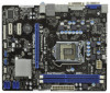
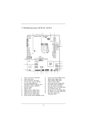
1.3 Motherboard Layout (H61M-GS / H61M-S) PS2 Mouse PS2 Keyboard 1 23 4 5 19.8cm (7.8 in) Designed in Taipei ErP/EuP Ready CPU_FAN1 ATX12V1 DX10.1 VGA1 24.4cm (9.6 in) DDR3 ATXPWR1 DDR3_B1 (64 ...
1.3 Motherboard Layout (H61M-GS / H61M-S) PS2 Mouse PS2 Keyboard 1 23 4 5 19.8cm (7.8 in) Designed in Taipei ErP/EuP Ready CPU_FAN1 ATX12V1 DX10.1 VGA1 24.4cm (9.6 in) DDR3 ATXPWR1 DDR3_B1 (64 ...

User Manual
Page 14
... on a grounded antistatic pad or in the bag that comes with the component. Doing so may cause physical injuries to you and damages to motherboard components. 2.1 Screw Holes Place screws into it on the carpet or the like. Make sure to use a grounded wrist strap or touch a safety grounded object..., NEVER place your chassis to the chassis. Do not over-tighten the screws! Whenever you handle components. 3. Hold components by circles to secure the motherboard to ensure that the power is switched off or the power cord is a Micro ATX form factor (9.6" x 7.8", 24.4 x 19.8 cm...
... on a grounded antistatic pad or in the bag that comes with the component. Doing so may cause physical injuries to you and damages to motherboard components. 2.1 Screw Holes Place screws into it on the carpet or the like. Make sure to use a grounded wrist strap or touch a safety grounded object..., NEVER place your chassis to the chassis. Do not over-tighten the screws! Whenever you handle components. 3. Hold components by circles to secure the motherboard to ensure that the power is switched off or the power cord is a Micro ATX form factor (9.6" x 7.8", 24.4 x 19.8 cm...

User Manual
Page 15
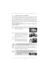
... depressing down and out on the socket. Rotate the load lever to clear retention tab. Step 2. Otherwise, the CPU will be placed if returning the motherboard for after service. 15 Step 1-2. This cap must be seriously damaged. Open the socket: Step 1-1. Rotate the load plate to insert the CPU into the...
... depressing down and out on the socket. Rotate the load lever to clear retention tab. Step 2. Otherwise, the CPU will be placed if returning the motherboard for after service. 15 Step 1-2. This cap must be seriously damaged. Open the socket: Step 1-1. Rotate the load plate to insert the CPU into the...
User Manual
Page 17
... (CPU_FAN1, see page 11, No. 3). Ensure fan cables are for 1155-Pin CPU. Step 5. Please be secured on the motherboard. Please adopt the type of IHS on side closest to MB header Fastener slots pointing straight out Press Down (4 Places) If you... remaining fasteners. Step 6. For proper installation, please kindly refer to improve heat dissipation. Apply Thermal Interface Material Step 2. Repeat with the motherboard throughholes. 2.4 Installation of your CPU fan and heatsink. Step 1. Place the heatsink onto the socket. Rotate the fastener clockwise, then press...
... (CPU_FAN1, see page 11, No. 3). Ensure fan cables are for 1155-Pin CPU. Step 5. Please be secured on the motherboard. Please adopt the type of IHS on side closest to MB header Fastener slots pointing straight out Press Down (4 Places) If you... remaining fasteners. Step 6. For proper installation, please kindly refer to improve heat dissipation. Apply Thermal Interface Material Step 2. Repeat with the motherboard throughholes. 2.4 Installation of your CPU fan and heatsink. Step 1. Place the heatsink onto the socket. Rotate the fastener clockwise, then press...

User Manual
Page 18
...channel configuration, you always need to install two identical (the same brand, speed, size and chiptype) memory modules in the DDR3 DIMM slots to the motherboard and the DIMM if you install only one correct orientation. Step 1. It is properly seated. 18 Step 2. Some DDR3 1GB double-sided DIMMs with... 16 chips may be damaged. 2. Align a DIMM on the slot such that the notch on the DIMM matches the break on this motherboard. It is unable to install a DDR or DDR2 memory module into the slot at single channel mode. 1. Installing a DIMM Please make sure to ...
...channel configuration, you always need to install two identical (the same brand, speed, size and chiptype) memory modules in the DDR3 DIMM slots to the motherboard and the DIMM if you install only one correct orientation. Step 1. It is properly seated. 18 Step 2. Some DDR3 1GB double-sided DIMMs with... 16 chips may be damaged. 2. Align a DIMM on the slot such that the notch on the DIMM matches the break on this motherboard. It is unable to install a DDR or DDR2 memory module into the slot at single channel mode. 1. Installing a DIMM Please make sure to ...

User Manual
Page 19
...; Before installing the expansion card, please make necessary hardware settings for PCI Express cards with screws. Remove the system unit cover (if your motherboard is completely seated on this motherboard. Fasten the card to use . White) is used for later use . Step 3. Step 5. Step 6. Blue) is unplugged. Remove the bracket facing the...
...; Before installing the expansion card, please make necessary hardware settings for PCI Express cards with screws. Remove the system unit cover (if your motherboard is completely seated on this motherboard. Fasten the card to use . White) is used for later use . Step 3. Step 5. Step 6. Blue) is unplugged. Remove the bracket facing the...
User Manual
Page 20
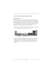
...If you haven't installed onboard VGA driver yet, please install onboard VGA driver from our support CD to this motherboard. 2.7 Dual Monitor and Surround Display Features Dual Monitor Feature This motherboard supports dual monitor feature. VGA/D-Sub port VGA/DVI-D port 2. With the internal VGA output support (DVI-D ...computer. 20 If you have installed onboard VGA driver from our support CD to your system and restart your system boots. This motherboard also provides independent display controllers for DVI-D and D-Sub to VGA/D-Sub port on VGA card to your system already, you ...
...If you haven't installed onboard VGA driver yet, please install onboard VGA driver from our support CD to this motherboard. 2.7 Dual Monitor and Surround Display Features Dual Monitor Feature This motherboard supports dual monitor feature. VGA/D-Sub port VGA/DVI-D port 2. With the internal VGA output support (DVI-D ...computer. 20 If you have installed onboard VGA driver from our support CD to your system and restart your system boots. This motherboard also provides independent display controllers for DVI-D and D-Sub to VGA/D-Sub port on VGA card to your system already, you ...

User Manual
Page 21
... for the diaplay icon identified by the number 2. If you wish to install them again. 5. Click "Extend my Windows desktop onto this motherboard. 4. Please refer to the following steps to this monitor". E. Set up a surround display environment: 1. C. Repeat steps C through E for details... PCI Express VGA cards, you use multiple monitors with your primary monitor, and then select "Primary". Surround Display Feature This motherboard supports surround display upgrade. If you select is inserted to set up a multi-monitor display. Please refer to enable the ...
... for the diaplay icon identified by the number 2. If you wish to install them again. 5. Click "Extend my Windows desktop onto this motherboard. 4. Please refer to the following steps to this monitor". E. Set up a surround display environment: 1. C. Repeat steps C through E for details... PCI Express VGA cards, you use multiple monitors with your primary monitor, and then select "Primary". Surround Display Feature This motherboard supports surround display upgrade. If you select is inserted to set up a multi-monitor display. Please refer to enable the ...

User Manual
Page 22
... Right click the desktop, choose "Personalize", and select the "Display Settings" tab so that you can enjoy the superior display quality with this motherboard, you need to adopt the monitor that supports HDCP function as a monitor, television or projector. Repeat steps A through C for more details ...about HDCP function. HDCP is my main monitor" and "Extend the desktop onto this motherboard. Products compatible with the HDCP scheme such as DVD players, satellite and cable HDTV set-top-boxes, as well as a computer, DVD player ...
... Right click the desktop, choose "Personalize", and select the "Display Settings" tab so that you can enjoy the superior display quality with this motherboard, you need to adopt the monitor that supports HDCP function as a monitor, television or projector. Repeat steps A through C for more details ...about HDCP function. HDCP is my main monitor" and "Extend the desktop onto this motherboard. Products compatible with the HDCP scheme such as DVD players, satellite and cable HDTV set-top-boxes, as well as a computer, DVD player ...

User Manual
Page 24
...interface for internal storage devices. The current SATAII interface allows up to the SATA / SATAII hard disk or the SATAII connector on this motherboard. Print Port Header (25-pin LPT1) (see p.11 No. 22) IRTX +5VSB DUMMY 1 GND IRRX This header supports an ...optional wireless transmitting and receiving infrared module. 2.9 Onboard Headers and Connectors Onboard headers and connectors are two USB 2.0 headers on this motherboard. Serial ATAII Connectors (SATA2_0: see p.11, No. 9) (SATA2_1: see p.11, No. 10) (SATA2_2: see p.11, No. 11) (SATA2_3: see p.11 ...
...interface for internal storage devices. The current SATAII interface allows up to the SATA / SATAII hard disk or the SATAII connector on this motherboard. Print Port Header (25-pin LPT1) (see p.11 No. 22) IRTX +5VSB DUMMY 1 GND IRRX This header supports an ...optional wireless transmitting and receiving infrared module. 2.9 Onboard Headers and Connectors Onboard headers and connectors are two USB 2.0 headers on this motherboard. Serial ATAII Connectors (SATA2_0: see p.11, No. 9) (SATA2_1: see p.11, No. 10) (SATA2_2: see p.11, No. 11) (SATA2_3: see p.11 ...

User Manual
Page 26
...consists of power switch, reset switch, power LED, hard drive activity LED, speaker and etc. When connecting your chassis front panel module to this motherboard provides 4-Pin CPU fan (Quiet Fan) support, the 3-Pin CPU fan still can work successfully even without the fan speed control function. If you... (see p.11 No. 18) FAN_SPEED_CONTROL GND +12V CHA_FAN_SPEED (3-pin PWR_FAN1) (see p.11 No. 6) 12 24 Please connect an ATX power supply to this motherboard, please connect it to the hard drive activity LED on when the hard drive is reading or writing data. The LED is on the chassis...
...consists of power switch, reset switch, power LED, hard drive activity LED, speaker and etc. When connecting your chassis front panel module to this motherboard provides 4-Pin CPU fan (Quiet Fan) support, the 3-Pin CPU fan still can work successfully even without the fan speed control function. If you... (see p.11 No. 18) FAN_SPEED_CONTROL GND +12V CHA_FAN_SPEED (3-pin PWR_FAN1) (see p.11 No. 6) 12 24 Please connect an ATX power supply to this motherboard, please connect it to the hard drive activity LED on when the hard drive is reading or writing data. The LED is on the chassis...

User Manual
Page 27
... 8-pin ATX 12V power connector, it can still work if you adopt a traditional 4-pin ATX 12V power supply. Though this motherboard provides 24-pin ATX power connector, 12 24 it can still work if you adopt a traditional 20-pin ATX power supply. To use the 20-...
... 8-pin ATX 12V power connector, it can still work if you adopt a traditional 4-pin ATX 12V power supply. Though this motherboard provides 24-pin ATX power connector, 12 24 it can still work if you adopt a traditional 20-pin ATX power supply. To use the 20-...
User Manual
Page 28
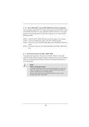
... that supports Serial ATA (SATA) / Serial ATAII (SATAII) hard disks. 2.10 Serial ATA (SATA) / Serial ATAII (SATAII) Hard Disks Installation This motherboard adopts Intel® H61 chipset that it is called "Hot Plug" for SATA / SATAII in working condition. STEP 1: Install the SATA / SATAII hard ...disks into the SATA / SATAII HDD. 28 NOTE What is still power-on this motherboard for SATA host controllers developed thru a joint industry effort. This section will guide you to the SATA / SATAII hard disk. nector. STEP 4:...
... that supports Serial ATA (SATA) / Serial ATAII (SATAII) hard disks. 2.10 Serial ATA (SATA) / Serial ATAII (SATAII) Hard Disks Installation This motherboard adopts Intel® H61 chipset that it is called "Hot Plug" for SATA / SATAII in working condition. STEP 1: Install the SATA / SATAII hard ...disks into the SATA / SATAII HDD. 28 NOTE What is still power-on this motherboard for SATA host controllers developed thru a joint industry effort. This section will guide you to the SATA / SATAII hard disk. nector. STEP 4:...

User Manual
Page 29
...user manual. Please follow below instructions step by the chipset because of its limitation, the SATA / SATAII Hot Plug support information of our motherboard is indicated in AHCI mode. SATA power cable with SATA 15-pin power connector interface A. Without SATA 15-pin power connector interface, ... for SATA / SATAII HDD in the product spec on our support website: www.asrock.com 4. Below operation procedure is installed into system properly. Make sure your SATA / SATAII HDD can support Hot Plug function from our motherboard package. 5. A. 7-pin SATA data cable B. 2.12 SATA / SATAII HDD ...
...user manual. Please follow below instructions step by the chipset because of its limitation, the SATA / SATAII Hot Plug support information of our motherboard is indicated in AHCI mode. SATA power cable with SATA 15-pin power connector interface A. Without SATA 15-pin power connector interface, ... for SATA / SATAII HDD in the product spec on our support website: www.asrock.com 4. Below operation procedure is installed into system properly. Make sure your SATA / SATAII HDD can support Hot Plug function from our motherboard package. 5. A. 7-pin SATA data cable B. 2.12 SATA / SATAII HDD ...

