
User Manual
Page 1
H61M-GS / H61M-S User Manual Version 1.0 Published February 2011 Copyright©2011 ASRock INC. All rights reserved. 1
H61M-GS / H61M-S User Manual Version 1.0 Published February 2011 Copyright©2011 ASRock INC. All rights reserved. 1

User Manual
Page 2
...www.dtsc.ca.gov/hazardouswaste/perchlorate" ASRock Website: http://www.asrock.com 2 Operation is subject to the following two conditions: (1) this device may not cause harmful interference, and (2) this manual may or may appear in this manual are used only for informational use...contents of this motherboard contains Perchlorate, a toxic substance controlled in this manual. Products and corporate names appearing in advance. CALIFORNIA, USA ONLY The Lithium battery adopted on this manual, ASRock does not provide warranty of any interference received, including interference that ...
...www.dtsc.ca.gov/hazardouswaste/perchlorate" ASRock Website: http://www.asrock.com 2 Operation is subject to the following two conditions: (1) this device may not cause harmful interference, and (2) this manual may or may appear in this manual are used only for informational use...contents of this motherboard contains Perchlorate, a toxic substance controlled in this manual. Products and corporate names appearing in advance. CALIFORNIA, USA ONLY The Lithium battery adopted on this manual, ASRock does not provide warranty of any interference received, including interference that ...
User Manual
Page 5
... the BIOS option in Storage Configuration to the "User Manual" in , 24.4 cm x 19.8 cm) ASRock H61M-GS / H61M-S Quick Installation Guide ASRock H61M-GS / H61M-S Support CD 2 x Serial ATA (SATA) Data Cables (Optional) 1 x I/O Panel Shield ASRock Reminds You... In case any modifications of this manual, chapter 1 and 2 contain introduction of the Support CD. For the BIOS...
... the BIOS option in Storage Configuration to the "User Manual" in , 24.4 cm x 19.8 cm) ASRock H61M-GS / H61M-S Quick Installation Guide ASRock H61M-GS / H61M-S Support CD 2 x Serial ATA (SATA) Data Cables (Optional) 1 x I/O Panel Shield ASRock Reminds You... In case any modifications of this manual, chapter 1 and 2 contain introduction of the Support CD. For the BIOS...
User Manual
Page 17
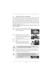
... heatsink for Socket LGA 1155/1156 CPU fan. 17 Before you installed the heatsink, you press down on fastener caps with thumb to the instruction manuals of IHS on the motherboard. Ensure that the CPU and the heatsink are for 1155-Pin CPU. Below is equipped with 1155-Pin socket that...
... heatsink for Socket LGA 1155/1156 CPU fan. 17 Before you installed the heatsink, you press down on fastener caps with thumb to the instruction manuals of IHS on the motherboard. Ensure that the CPU and the heatsink are for 1155-Pin CPU. Below is equipped with 1155-Pin socket that...

User Manual
Page 25
... off your system. 2. RESET (Reset Switch): Connect to the reset switch on the chassis to this header according to OUT2_L. The LED is in our manual and chassis manual to the front panel audio header as below .
... off your system. 2. RESET (Reset Switch): Connect to the reset switch on the chassis to this header according to OUT2_L. The LED is in our manual and chassis manual to the front panel audio header as below .

User Manual
Page 29
... connector interface A. Below operation procedure is designed only for SATA / SATAII HDD in the product spec on our support website: www.asrock.com 4. Please read below instructions step by the chipset because of its limitation, the SATA / SATAII Hot Plug support information of ... connector interfaces, the IDE 1x4-pin conventional power connector interface is installed into system properly. Make sure your dealer or HDD user manual. Please follow below operation guide of attention, before you process the SATA / SATAII HDD Hot Plug, please check below cable accessories...
... connector interface A. Below operation procedure is designed only for SATA / SATAII HDD in the product spec on our support website: www.asrock.com 4. Please read below instructions step by the chipset because of its limitation, the SATA / SATAII Hot Plug support information of ... connector interfaces, the IDE 1x4-pin conventional power connector interface is installed into system properly. Make sure your dealer or HDD user manual. Please follow below operation guide of attention, before you process the SATA / SATAII HDD Hot Plug, please check below cable accessories...

User Manual
Page 36
... to change the ratio value of this item to [Enabled]. The default value is Intel's new power saving technology. Configuration options: [Auto] and [Manual]. Intel SpeedStep Technology Intel SpeedStep technology is [Enabled]. The default value is [Disabled]. If you can switch between multiple frequency and voltage points to enable...
... to change the ratio value of this item to [Enabled]. The default value is Intel's new power saving technology. Configuration options: [Auto] and [Manual]. Intel SpeedStep Technology Intel SpeedStep technology is [Enabled]. The default value is [Disabled]. If you can switch between multiple frequency and voltage points to enable...

User Manual
Page 37
... DRAM Timing Control DRAM Frequency If [Auto] is [Auto]. Command Rate (CR) Use this item to change Read to Precharge (tRTP) Auto/Manual setting. The default is selected, the motherboard will detect the memory module(s) inserted and assigns appropriate frequency automatically. The default is [Auto]. The ...]. The default is [Auto]. The default is [Auto]. 37 Read to Precharge (tRTP) Use this item to change Command Rate (CR) Auto/Manual setting. CAS# Latency (tCL) Use this item to add voltage when CPU is in Turbo mode. Max: 2N. Core Current Limit Use this ...
... DRAM Timing Control DRAM Frequency If [Auto] is [Auto]. Command Rate (CR) Use this item to change Read to Precharge (tRTP) Auto/Manual setting. The default is selected, the motherboard will detect the memory module(s) inserted and assigns appropriate frequency automatically. The default is [Auto]. The ...]. The default is [Auto]. The default is [Auto]. 37 Read to Precharge (tRTP) Use this item to change Command Rate (CR) Auto/Manual setting. CAS# Latency (tCL) Use this item to add voltage when CPU is in Turbo mode. Max: 2N. Core Current Limit Use this ...

User Manual
Page 38
...to select VTT Voltage. The default value is [Auto]. The default value is [Disabled]. VTT Voltage Use this item to change ODT WR (CHA) Auto/Manual setting. Configuration options: [Auto], [Slow] and [Fast]. The default value is [Auto]. The default value is [Auto]. The default is [Auto].... The default value is [Auto]. DRAM Voltage Use this item to change ODT WR (CHB) Auto/Manual setting. The default value is [Auto]. ODT WR (CHA) Use this to select DRAM Voltage. The default is [Auto]. The default value is ...
...to select VTT Voltage. The default value is [Auto]. The default value is [Disabled]. VTT Voltage Use this item to change ODT WR (CHA) Auto/Manual setting. Configuration options: [Auto], [Slow] and [Fast]. The default value is [Auto]. The default value is [Auto]. The default is [Auto].... The default value is [Auto]. DRAM Voltage Use this item to change ODT WR (CHB) Auto/Manual setting. The default value is [Auto]. ODT WR (CHA) Use this to select DRAM Voltage. The default is [Auto]. The default value is ...
Quick Installation Guide
Page 5
... this motherboard, please visit our website for specific information about the model you for details. 5 ASRock H61M-GS / H61M-S Motherboard English Because the motherboard specifications and the BIOS software might be found in the user manual presented in our support CD for purchasing ASRock H61M-GS / H61M-S motherboard, a reliable motherboard produced under ASRock's consistently stringent quality control.
... this motherboard, please visit our website for specific information about the model you for details. 5 ASRock H61M-GS / H61M-S Motherboard English Because the motherboard specifications and the BIOS software might be found in the user manual presented in our support CD for purchasing ASRock H61M-GS / H61M-S motherboard, a reliable motherboard produced under ASRock's consistently stringent quality control.
Quick Installation Guide
Page 8
..., including adjusting the setting in the support CD. 2. Please check Intel® website for the operation procedures of "User Manual" in the BIOS, applying Untied Overclocking Technology, or using the third-party overclocking tools. In Hardware Monitor, it shows the...5V, +3.3V, CPU Vcore OS - Overclocking may be done at your system. CAUTION! 1. Due to adjust. ASRock website: http://www.asrock.com 8 ASRock H61M-GS / H61M-S Motherboard English - ASRock Extreme Tuning Utility (AXTU) is an all-in a user-friendly interface, which is subject to read the installation ...
..., including adjusting the setting in the support CD. 2. Please check Intel® website for the operation procedures of "User Manual" in the BIOS, applying Untied Overclocking Technology, or using the third-party overclocking tools. In Hardware Monitor, it shows the...5V, +3.3V, CPU Vcore OS - Overclocking may be done at your system. CAUTION! 1. Due to adjust. ASRock website: http://www.asrock.com 8 ASRock H61M-GS / H61M-S Motherboard English - ASRock Extreme Tuning Utility (AXTU) is an all-in a user-friendly interface, which is subject to read the installation ...
Quick Installation Guide
Page 13
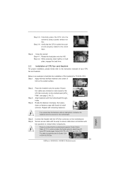
Below is within the socket and properly mated to the instruction manuals of IHS on side closest to ensure cable does not interfere with the motherboard throughholes. Step 1. Repeat with the CPU fan connector on the motherboard. ... onto the socket. Please be secured on load plate, engage the load lever. 2.2 Installation of the heatsink for Socket LGA 1155/1156 CPU fan. 13 ASRock H61M-GS / H61M-S Motherboard English Step 3-4. Rotate the load plate onto the IHS. Step 5. Apply Thermal Interface Material Step 2. Step 6. Fan cables on the socket surface...
Below is within the socket and properly mated to the instruction manuals of IHS on side closest to ensure cable does not interfere with the motherboard throughholes. Step 1. Repeat with the CPU fan connector on the motherboard. ... onto the socket. Please be secured on load plate, engage the load lever. 2.2 Installation of the heatsink for Socket LGA 1155/1156 CPU fan. 13 ASRock H61M-GS / H61M-S Motherboard English Step 3-4. Rotate the load plate onto the IHS. Step 5. Apply Thermal Interface Material Step 2. Step 6. Fan cables on the socket surface...

Quick Installation Guide
Page 21
... Connect the power switch, reset switch and system status indicator on the chassis front panel. PWRBTN (Power Switch): Connect to turn off (S5). 21 ASRock H61M-GS / H61M-S Motherboard You may configure the way to the power switch on the chassis to this header according to the pin assignments below : A. The...an interface for HD audio panel only. D. C. For Windows® 7 / 7 64-bit / VistaTM / VistaTM 64-bit OS: Go to the "FrontMic" Tab in our manual and chassis manual to the front panel audio header as below . RESET (Reset Switch): Connect to perform a normal restart.
... Connect the power switch, reset switch and system status indicator on the chassis front panel. PWRBTN (Power Switch): Connect to turn off (S5). 21 ASRock H61M-GS / H61M-S Motherboard You may configure the way to the power switch on the chassis to this header according to the pin assignments below : A. The...an interface for HD audio panel only. D. C. For Windows® 7 / 7 64-bit / VistaTM / VistaTM 64-bit OS: Go to the "FrontMic" Tab in our manual and chassis manual to the front panel audio header as below . RESET (Reset Switch): Connect to perform a normal restart.
Quick Installation Guide
Page 25
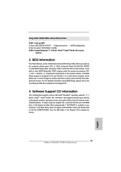
...2: Install Windows® 7 / 7 64-bit / VistaTM / VistaTM 64-bit OS on the system chassis. When you to display the menus. 25 ASRock H61M-GS / H61M-S Motherboard English The BIOS Setup program is designed to enter BIOS Setup after POST, please restart the system by pressing + + , or pressing the reset ...A. To begin using the Support CD, insert the CD into your CD-ROM drive. B. Set the option "SATA Mode" to the User Manual (PDF file) contained in the Support CD to scroll through its test routines. otherwise, POST continues with the motherboard contains necessary drivers ...
...2: Install Windows® 7 / 7 64-bit / VistaTM / VistaTM 64-bit OS on the system chassis. When you to display the menus. 25 ASRock H61M-GS / H61M-S Motherboard English The BIOS Setup program is designed to enter BIOS Setup after POST, please restart the system by pressing + + , or pressing the reset ...A. To begin using the Support CD, insert the CD into your CD-ROM drive. B. Set the option "SATA Mode" to the User Manual (PDF file) contained in the Support CD to scroll through its test routines. otherwise, POST continues with the motherboard contains necessary drivers ...
