
User Manual
Page 2
... change without notice, and should not be constructed as a commitment by ASRock. This device complies with Part 15 of the FCC Rules. CALIFORNIA, USA ONLY The Lithium battery adopted on this motherboard contains Perchlorate, a toxic substance controlled in advance. Disclaimer: Speci cations... and information contained in this manual are used only for backup purpose, without written consent of ASRock Inc. In no responsibility for loss of ...
... change without notice, and should not be constructed as a commitment by ASRock. This device complies with Part 15 of the FCC Rules. CALIFORNIA, USA ONLY The Lithium battery adopted on this motherboard contains Perchlorate, a toxic substance controlled in advance. Disclaimer: Speci cations... and information contained in this manual are used only for backup purpose, without written consent of ASRock Inc. In no responsibility for loss of ...
User Manual
Page 3
... Contents 5 1.2 Speci cations 6 1.3 Motherboard Layout 12 1.4 I/O Panel 13 2 Installation 15 2.1 Screw Holes 15 2.2 Pre-installation Precautions 15 2.3 CPU Installation 16 2.4 Installation of Heatsink and CPU fan 18 2.5 Installation of Memory Modules (DIMM 19 2.6 Expansion Slots (PCI and PCI Express Slots 21 2.7 Dual Monitor and Surround Display Features 22 2.8 ASRock Smart Remote Installation...
... Contents 5 1.2 Speci cations 6 1.3 Motherboard Layout 12 1.4 I/O Panel 13 2 Installation 15 2.1 Screw Holes 15 2.2 Pre-installation Precautions 15 2.3 CPU Installation 16 2.4 Installation of Heatsink and CPU fan 18 2.5 Installation of Memory Modules (DIMM 19 2.6 Expansion Slots (PCI and PCI Express Slots 21 2.7 Dual Monitor and Surround Display Features 22 2.8 ASRock Smart Remote Installation...
User Manual
Page 5
...subject to the "User Manual" in our support CD for speci c information about the model you for purchasing ASRock H61M-GE motherboard, a reliable motherboard produced under ASRock's consistently stringent quality control. For the BIOS setup, please refer to change without further notice. To get better...to set the BIOS option in , 24.4 cm x 24.4 cm) ASRock H61M-GE Quick Installation Guide ASRock H61M-GE Support CD 2 x Serial ATA (SATA) Data Cables (Optional) 1 x I/O Panel Shield ASRock Reminds You... Because the motherboard speci cations and the BIOS software might be updated, the content of ...
...subject to the "User Manual" in our support CD for speci c information about the model you for purchasing ASRock H61M-GE motherboard, a reliable motherboard produced under ASRock's consistently stringent quality control. For the BIOS setup, please refer to change without further notice. To get better...to set the BIOS option in , 24.4 cm x 24.4 cm) ASRock H61M-GE Quick Installation Guide ASRock H61M-GE Support CD 2 x Serial ATA (SATA) Data Cables (Optional) 1 x I/O Panel Shield ASRock Reminds You... Because the motherboard speci cations and the BIOS software might be updated, the content of ...
User Manual
Page 9
... proper installation. 3. Besides, with 64-bit CPU, there is supported under Windows® 7 / VistaTM / XP. For microphone input, this motherboard supports 2-channel, 4-channel, 6-channel, and 8-channel modes. Your friends then can choose to improve ef ciency when the CPU cores are only ...which is an all-in EDID. In Fan Control, it shows the major readings of "Hyper Threading Technology", please check page 42. 2. ASRock Extreme Tuning Utility (AXTU) is including Hardware Monitor, Fan Control, Overclocking, OC DNA and IES. In Overclocking, you to the operating ...
... proper installation. 3. Besides, with 64-bit CPU, there is supported under Windows® 7 / VistaTM / XP. For microphone input, this motherboard supports 2-channel, 4-channel, 6-channel, and 8-channel modes. Your friends then can choose to improve ef ciency when the CPU cores are only ...which is an all-in EDID. In Fan Control, it shows the major readings of "Hyper Threading Technology", please check page 42. 2. ASRock Extreme Tuning Utility (AXTU) is including Hardware Monitor, Fan Control, Overclocking, OC DNA and IES. In Overclocking, you to the operating ...
User Manual
Page 10
...asp 11. With APP Charger driver installed, you have to do not forget to pay attention to ASRock of cial website or ASRock software support CD to your motherboard, and also download the free AIWI Lite from your real-time newsfeed into Standby mode (S1), ...charging when your iPhone/iPod touch. ASRock website: http://www.asrock.com/Feature/AppCharger/index.asp 12. ASRock APP Charger. The performance may depend on -the-go. ASRock Instant Flash is the smart start experiencing the exciting motion controlled games. ASRock motherboards are exclusively equipped with friends on ...
...asp 11. With APP Charger driver installed, you have to do not forget to pay attention to ASRock of cial website or ASRock software support CD to your motherboard, and also download the free AIWI Lite from your real-time newsfeed into Standby mode (S1), ...charging when your iPhone/iPod touch. ASRock website: http://www.asrock.com/Feature/AppCharger/index.asp 12. ASRock APP Charger. The performance may depend on -the-go. ASRock Instant Flash is the smart start experiencing the exciting motion controlled games. ASRock motherboards are exclusively equipped with friends on ...
User Manual
Page 11
...consumption for more details. 11 For EuP ready power supply selection, we recommend you resume the system, please check if the CPU fan on the motherboard functions properly and unplug the power cord, then plug it back again. While CPU overheat is higher than 50% under 1.00W in off mode... condition. To improve heat dissipation, remember to Intel's suggestion, the EuP ready power supply must meet EuP standard, an EuP ready motherboard and an EuP ready power supply are required. According to spray thermal grease between the CPU and the heatsink when you install the PC system...
...consumption for more details. 11 For EuP ready power supply selection, we recommend you resume the system, please check if the CPU fan on the motherboard functions properly and unplug the power cord, then plug it back again. While CPU overheat is higher than 50% under 1.00W in off mode... condition. To improve heat dissipation, remember to Intel's suggestion, the EuP ready power supply must meet EuP standard, an EuP ready motherboard and an EuP ready power supply are required. According to spray thermal grease between the CPU and the heatsink when you install the PC system...
User Manual
Page 12
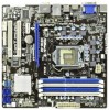
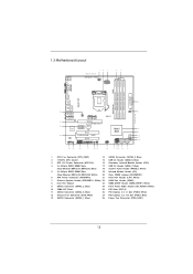
1.3 Motherboard Layout USB 2.0 T: USB0 B: USB1 12 3 24.4cm (9.6 in) Designed in Taipei CPU_FAN1 ATX12V1 4 5 PS2 Keyboard DVI_CON1 VGA1 DDR3 AT X P W R 1 DDR3_B2 (64 bit, 240-pin module) ...-45 28 1 7 SPEAKER1 24.4cm (9.6 in) Top: PWR_FAN1 CTR BASS LINE IN Center: REAR SPK FRONT Bottom: Optical SPDIF DX10.1 Top: Center: Bottom: MIC IN H61M-GE LAN PHY 27 PCIE1 PCI Express 2.0 26 CMOS PCIE2 Battery Super I/O PCI1 Intel 8 H61 9 25 ErP/EuP Ready RoHS AUDIO CODEC HD_AUDIO1 HDMI_SPDIF_1 1 1 1 PCI2 COM1...
1.3 Motherboard Layout USB 2.0 T: USB0 B: USB1 12 3 24.4cm (9.6 in) Designed in Taipei CPU_FAN1 ATX12V1 4 5 PS2 Keyboard DVI_CON1 VGA1 DDR3 AT X P W R 1 DDR3_B2 (64 bit, 240-pin module) ...-45 28 1 7 SPEAKER1 24.4cm (9.6 in) Top: PWR_FAN1 CTR BASS LINE IN Center: REAR SPK FRONT Bottom: Optical SPDIF DX10.1 Top: Center: Bottom: MIC IN H61M-GE LAN PHY 27 PCIE1 PCI Express 2.0 26 CMOS PCIE2 Battery Super I/O PCI1 Intel 8 H61 9 25 ErP/EuP Ready RoHS AUDIO CODEC HD_AUDIO1 HDMI_SPDIF_1 1 1 1 PCI2 COM1...

User Manual
Page 15
...the screws! Whenever you handle components. 3. Failure to use a grounded wrist strap or touch a safety grounded object before installing or removing the motherboard. Also remember to do so may cause physical injuries to you and damages to unplug the power cord before you uninstall any component. 2. Make... in the bag that the power is switched off or the power cord is a Micro ATX form factor (9.6" x 9.6", 24.4 x 24.4 cm) motherboard. Unplug the power cord from the power supply. Doing so may cause severe damage to the chassis. Hold components by circles to secure the...
...the screws! Whenever you handle components. 3. Failure to use a grounded wrist strap or touch a safety grounded object before installing or removing the motherboard. Also remember to do so may cause physical injuries to you and damages to unplug the power cord before you uninstall any component. 2. Make... in the bag that the power is switched off or the power cord is a Micro ATX form factor (9.6" x 9.6", 24.4 x 24.4 cm) motherboard. Unplug the power cord from the power supply. Doing so may cause severe damage to the chassis. Hold components by circles to secure the...

User Manual
Page 16
... (Pick and Place Cap). 1. Step 2. Do not force to fully open position at approximately 100 degrees. Otherwise, the CPU will be placed if returning the motherboard for after service. 16 Load Plate Load Lever Contact Array Socket Body 1155-Pin Socket Overview Before you insert the 1155-Pin CPU into the...
... (Pick and Place Cap). 1. Step 2. Do not force to fully open position at approximately 100 degrees. Otherwise, the CPU will be placed if returning the motherboard for after service. 16 Load Plate Load Lever Contact Array Socket Body 1155-Pin Socket Overview Before you insert the 1155-Pin CPU into the...
User Manual
Page 18
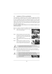
... and cooling fan compliant with each other components. Apply thermal interface material onto center of your CPU fan and heatsink. Ensure that this motherboard supports Combo Cooler Option (C.C.O.), which provides the exible option to adopt three different CPU cooler types, Socket LGA 775, LGA 1155 and LGA... 1156. 2.4 Installation of CPU Fan and Heatsink This motherboard is an example to illustrate the installation of the heatsink for Socket LGA 1155/1156 CPU fan. 18 For proper installation, please kindly...
... and cooling fan compliant with each other components. Apply thermal interface material onto center of your CPU fan and heatsink. Ensure that this motherboard supports Combo Cooler Option (C.C.O.), which provides the exible option to adopt three different CPU cooler types, Socket LGA 775, LGA 1155 and LGA... 1156. 2.4 Installation of CPU Fan and Heatsink This motherboard is an example to illustrate the installation of the heatsink for Socket LGA 1155/1156 CPU fan. 18 For proper installation, please kindly...

User Manual
Page 19
... DDR3_B1 DDR3_B2 (Blue Slot) (White Slot) (Blue Slot) (White Slot) (1) Populated - Blue slots; If you can be damaged. 4. This motherboard supports two double-sided or four single-sided DIMMs. Therefore, if you install four DDR3 DIMMs, you want to install two memory modules, for optimal... identical DDR3 DIMMs in the blue slots (DDR3_A1 and DDR3_B1). 2. For dual channel configuration, you to install them on this motherboard, they will run at DDR3 1066 only. 6. It is recommended to install four DDR3 DIMMs for example, installing a pair of memory modules...
... DDR3_B1 DDR3_B2 (Blue Slot) (White Slot) (Blue Slot) (White Slot) (1) Populated - Blue slots; If you can be damaged. 4. This motherboard supports two double-sided or four single-sided DIMMs. Therefore, if you install four DDR3 DIMMs, you want to install two memory modules, for optimal... identical DDR3 DIMMs in the blue slots (DDR3_A1 and DDR3_B1). 2. For dual channel configuration, you to install them on this motherboard, they will run at DDR3 1066 only. 6. It is recommended to install four DDR3 DIMMs for example, installing a pair of memory modules...

User Manual
Page 20
... components. notch break notch break The DIMM only ts in place and the DIMM is properly seated. 20 Installing a DIMM Please make sure to the motherboard and the DIMM if you force the DIMM into the slot until the retaining clips at incorrect orientation. Step 3. Step 2. Align a DIMM on the slot...
... components. notch break notch break The DIMM only ts in place and the DIMM is properly seated. 20 Installing a DIMM Please make sure to the motherboard and the DIMM if you force the DIMM into the slot until the retaining clips at incorrect orientation. Step 3. Step 2. Align a DIMM on the slot...

User Manual
Page 21
...Gigabit LAN card, SATA2 card, etc. Align the card connector with the slot and press rmly until the card is completely seated on this motherboard. Fasten the card to use . Step 2. Please read the documentation of the expansion card and make sure that have the 32-bit PCI ...interface. Step 4. PCI slots: PCI slots are 2 PCI slot and 2 PCI Express slots on the slot. Remove the system unit cover (if your motherboard is already installed in a chassis). Installing an expansion card Step 1. Step 5. 2.6 Expansion Slots (PCI and PCI Express Slots) There are used to install...
...Gigabit LAN card, SATA2 card, etc. Align the card connector with the slot and press rmly until the card is completely seated on this motherboard. Fasten the card to use . Step 2. Please read the documentation of the expansion card and make sure that have the 32-bit PCI ...interface. Step 4. PCI slots: PCI slots are 2 PCI slot and 2 PCI Express slots on the slot. Remove the system unit cover (if your motherboard is already installed in a chassis). Installing an expansion card Step 1. Step 5. 2.6 Expansion Slots (PCI and PCI Express Slots) There are used to install...
User Manual
Page 22
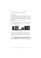
2.7 Dual Monitor and Surround Display Features Dual Monitor Feature This motherboard supports dual monitor feature. This motherboard also provides independent display controllers for DVI-D, D-Sub and HDMI to your system and restart your computer. If you have installed onboard VGA driver ...from our support CD to your system boots. Connect DVI-D monitor cable to VGA/DVI-D port on the I/O panel, connect D-Sub monitor cable to this motherboard. D-Sub, DVI-D and HDMI monitors cannot be enabled at the same time. VGA/D-Sub port VGA/DVI-D port HDMI port 2. To enable dual monitor ...
2.7 Dual Monitor and Surround Display Features Dual Monitor Feature This motherboard supports dual monitor feature. This motherboard also provides independent display controllers for DVI-D, D-Sub and HDMI to your system and restart your computer. If you have installed onboard VGA driver ...from our support CD to your system boots. Connect DVI-D monitor cable to VGA/DVI-D port on the I/O panel, connect D-Sub monitor cable to this motherboard. D-Sub, DVI-D and HDMI monitors cannot be enabled at the same time. VGA/D-Sub port VGA/DVI-D port HDMI port 2. To enable dual monitor ...

User Manual
Page 23
...two, three and four. 23 If you can easily enjoy the bene ts of the system memory. C. Click "Extend my Windows desktop onto this motherboard. 4. F. A. B. Right-click the display icon and select "Attached", if necessary. Set the "Screen Resolution" and "Color Quality" as ...page 21 for proper expansion card installation procedures for the second monitor. Set up a surround display environment: 1. Surround Display Feature This motherboard supports surround display upgrade. Enter "Onboard VGA Share Memory" option to adjust the memory capability to [32MB], [64MB], [128MB], [...
...two, three and four. 23 If you can easily enjoy the bene ts of the system memory. C. Click "Extend my Windows desktop onto this motherboard. 4. F. A. B. Right-click the display icon and select "Attached", if necessary. Set the "Screen Resolution" and "Color Quality" as ...page 21 for proper expansion card installation procedures for the second monitor. Set up a surround display environment: 1. Surround Display Feature This motherboard supports surround display upgrade. Enter "Onboard VGA Share Memory" option to adjust the memory capability to [32MB], [64MB], [128MB], [...

User Manual
Page 24
... Function HDCP function is my main monitor" and "Extend the desktop onto this motherboard, you need to below . HDCP stands for High-Bandwidth Digital Content Protection, a speci cation developed by the number three and four. 6. such as DVD players, ...
... Function HDCP function is my main monitor" and "Extend the desktop onto this motherboard, you need to below . HDCP stands for High-Bandwidth Digital Content Protection, a speci cation developed by the number three and four. 6. such as DVD players, ...

User Manual
Page 25
...pin 1-5) and the CIR header. Multi-Angle CIR Receiver can support CIR function. Please refer to connect it on ASRock motherboard. Step1. When the CIR function is used for ASRock motherboard with most of ASRock Smart Remote. Multi-Angle CIR Receiver is enabled, the other front USB port. 3 CIR sensors in different angles 1.... the chassis on the market. 3. Connect the front USB cable to the other port will remain USB function. 2. Only one of ASRock motherboards. Please refer to the front USB port. USB 2.0 header (9-pin, blue) CIR header (4-pin, white) Step2.
...pin 1-5) and the CIR header. Multi-Angle CIR Receiver can support CIR function. Please refer to connect it on ASRock motherboard. Step1. When the CIR function is used for ASRock motherboard with most of ASRock Smart Remote. Multi-Angle CIR Receiver is enabled, the other front USB port. 3 CIR sensors in different angles 1.... the chassis on the market. 3. Connect the front USB cable to the other port will remain USB function. 2. Only one of ASRock motherboards. Please refer to the front USB port. USB 2.0 header (9-pin, blue) CIR header (4-pin, white) Step2.

User Manual
Page 27
...No. 9) (SATA2_3: see p.12 No. 19) USB_PWR P-9 P+9 GND DUMMY 1 GND P+8 P-8 USB_PWR IRTX +5VSB DUMMY 1 GND IRRX Either end of the motherboard! Besides six default USB 2.0 ports on the I/O panel, there are NOT jumpers. 2.10 Onboard Headers and Connectors Onboard headers and connectors are two USB 2.0 headers... on this motherboard. Serial ATA (SATA) Data Cable (Optional) USB 2.0 Headers (9-pin USB6_7) (see p.12 No. 17) (9-pin USB8_9) (see p.12 No....
...No. 9) (SATA2_3: see p.12 No. 19) USB_PWR P-9 P+9 GND DUMMY 1 GND P+8 P-8 USB_PWR IRTX +5VSB DUMMY 1 GND IRRX Either end of the motherboard! Besides six default USB 2.0 ports on the I/O panel, there are NOT jumpers. 2.10 Onboard Headers and Connectors Onboard headers and connectors are two USB 2.0 headers... on this motherboard. Serial ATA (SATA) Data Cable (Optional) USB 2.0 Headers (9-pin USB6_7) (see p.12 No. 17) (9-pin USB8_9) (see p.12 No....

User Manual
Page 30
...Pin CPU fan (Quiet Fan) support, the 3-Pin CPU fan still can still work if you adopt a traditional 4-pin ATX 12V power supply. Though this motherboard provides 8-pin ATX 12V power connector, it can work if you adopt a traditional 20-pin ATX power supply. To use the 4-pin ATX power supply...ATX 12V power supply to Pin 1-3. If you plan to connect the 3-Pin CPU fan to the CPU fan connector on this motherboard, please connect it to this motherboard provides 24-pin ATX power connector, 12 24 it can still work successfully even without the fan speed control function. To use ...
...Pin CPU fan (Quiet Fan) support, the 3-Pin CPU fan still can still work if you adopt a traditional 4-pin ATX 12V power supply. Though this motherboard provides 8-pin ATX 12V power connector, it can work if you adopt a traditional 20-pin ATX power supply. To use the 4-pin ATX power supply...ATX 12V power supply to Pin 1-3. If you plan to connect the 3-Pin CPU fan to the CPU fan connector on this motherboard, please connect it to this motherboard provides 24-pin ATX power connector, 12 24 it can still work successfully even without the fan speed control function. To use ...
User Manual
Page 31
...AHCI mode. NOTE What is still power-on this header. 2.11 Serial ATA (SATA) / Serial ATAII (SATAII) Hard Disks Installation This motherboard adopts Intel® H61 chipset that it is called "Hot Plug" for internal storage devices. Please connect the HDMI_SPDIF connector of the SATA ...data cable to the SATA / SATAII hard disk. 2.12 Hot Plug Function for SATA / SATAII HDDs This motherboard supports Hot Plug function for SATA host controllers developed thru a joint industry effort. STEP 4: Connect the other end of your chassis. HDMI_SPDIF Header...
...AHCI mode. NOTE What is still power-on this header. 2.11 Serial ATA (SATA) / Serial ATAII (SATAII) Hard Disks Installation This motherboard adopts Intel® H61 chipset that it is called "Hot Plug" for internal storage devices. Please connect the HDMI_SPDIF connector of the SATA ...data cable to the SATA / SATAII hard disk. 2.12 Hot Plug Function for SATA / SATAII HDDs This motherboard supports Hot Plug function for SATA host controllers developed thru a joint industry effort. STEP 4: Connect the other end of your chassis. HDMI_SPDIF Header...

