User Manual
Page 1
H61M-GE User Manual Version 1.0 Published February 2011 Copyright©2011 ASRock INC. All rights reserved. 1
H61M-GE User Manual Version 1.0 Published February 2011 Copyright©2011 ASRock INC. All rights reserved. 1

User Manual
Page 2
...respect to the following two conditions: (1) this device may apply, see www.dtsc.ca.gov/hazardouswaste/perchlorate" ASRock Website: http://www.asrock.com 2 Copyright Notice: No part of this manual may be liable for any indirect, special, incidental, or consequential damages (including damages for loss of pro... arising from any defect or error in the manual or product. In no responsibility for any kind, either expressed or implied, including but not limited to infringe. Operation is subject to the contents of this manual, ASRock does not provide warranty of any errors or ...
...respect to the following two conditions: (1) this device may apply, see www.dtsc.ca.gov/hazardouswaste/perchlorate" ASRock Website: http://www.asrock.com 2 Copyright Notice: No part of this manual may be liable for any indirect, special, incidental, or consequential damages (including damages for loss of pro... arising from any defect or error in the manual or product. In no responsibility for any kind, either expressed or implied, including but not limited to infringe. Operation is subject to the contents of this manual, ASRock does not provide warranty of any errors or ...
User Manual
Page 5
... the Support CD. Chapter 3 and 4 contain the con guration guide to BIOS setup and information of this manual will be subject to the "User Manual" in our support CD for purchasing ASRock H61M-GE motherboard, a reliable motherboard produced under ASRock's consistently stringent quality control. In this motherboard, please visit our website for speci c information about the...
... the Support CD. Chapter 3 and 4 contain the con guration guide to BIOS setup and information of this manual will be subject to the "User Manual" in our support CD for purchasing ASRock H61M-GE motherboard, a reliable motherboard produced under ASRock's consistently stringent quality control. In this motherboard, please visit our website for speci c information about the...
User Manual
Page 18
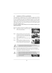
... fasteners. Step 6. The white throughholes are securely fastened and in good contact with each other components. For proper installation, please kindly refer to the instruction manuals of IHS on the socket surface. Below is equipped with 1155-Pin socket that the CPU and the heatsink are for 1155-Pin CPU. Step...
... fasteners. Step 6. The white throughholes are securely fastened and in good contact with each other components. For proper installation, please kindly refer to the instruction manuals of IHS on the socket surface. Below is equipped with 1155-Pin socket that the CPU and the heatsink are for 1155-Pin CPU. Step...

User Manual
Page 28
... system front panel functions. 28 Connect Mic_IN (MIC) to Ground (GND). Connect Audio_R (RIN) to OUT2_R and Audio_L (LIN) to the "FrontMic" Tab in our manual and chassis manual to function correctly. D. To activate the front mic. For Windows® 7 / 7 64-bit / VistaTM / VistaTM 64-bit OS: Go to OUT2_L.
... system front panel functions. 28 Connect Mic_IN (MIC) to Ground (GND). Connect Audio_R (RIN) to OUT2_R and Audio_L (LIN) to the "FrontMic" Tab in our manual and chassis manual to function correctly. D. To activate the front mic. For Windows® 7 / 7 64-bit / VistaTM / VistaTM 64-bit OS: Go to OUT2_L.

User Manual
Page 32
...process the SATA / SATAII HDD Hot Plug, please check below operation guide of Hot Plug feature carefully. Make sure your dealer or HDD user manual. Make sure to use the SATA power cable & data cable, which are from your SATA / SATAII HDD can support Hot Plug function from... operation procedure is indicated in AHCI mode. SATA data cable (Red) B. Please make sure the SATA / SATAII driver is available on our website: www.asrock.com 2. The latest SATA / SATAII driver is installed into system properly. SATA power cable SATA 7-pin connector The SATA 15-pin power connector (Black)...
...process the SATA / SATAII HDD Hot Plug, please check below operation guide of Hot Plug feature carefully. Make sure your dealer or HDD user manual. Make sure to use the SATA power cable & data cable, which are from your SATA / SATAII HDD can support Hot Plug function from... operation procedure is indicated in AHCI mode. SATA data cable (Red) B. Please make sure the SATA / SATAII driver is available on our website: www.asrock.com 2. The latest SATA / SATAII driver is installed into system properly. SATA power cable SATA 7-pin connector The SATA 15-pin power connector (Black)...

User Manual
Page 38
...]. Please note that overclocking may reduce CPU voltage and lead to system stability or compatibility issue with some power supplies. Con guration options: [Auto] and [Manual]. If you can switch between multiple frequency and voltage points to run faster than marked frequency in speci c condition. Turbo Boost Power Limit Use this...
...]. Please note that overclocking may reduce CPU voltage and lead to system stability or compatibility issue with some power supplies. Con guration options: [Auto] and [Manual]. If you can switch between multiple frequency and voltage points to run faster than marked frequency in speci c condition. Turbo Boost Power Limit Use this...

User Manual
Page 39
... default is [Auto]. The default is [Auto]. Write to Read Delay (tWTR) Use this item to change Write Recovery Time (tWR) Auto/Manual setting. The default is selected, the motherboard will detect the memory module(s) inserted and assigns appropriate frequency automatically. Write Recovery Time (tWR) Use ...]. The default is [Auto]. 39 The default is [Auto]. CAS# Latency (tCL) Use this item to change Refresh Cyle Time (tRFC) Auto/Manual setting. The default is [Auto]. The default is [Auto]. Max: 2N. The default is [Auto]. Refresh Cyle Time (tRFC) Use this item...
... default is [Auto]. The default is [Auto]. Write to Read Delay (tWTR) Use this item to change Write Recovery Time (tWR) Auto/Manual setting. The default is selected, the motherboard will detect the memory module(s) inserted and assigns appropriate frequency automatically. Write Recovery Time (tWR) Use ...]. The default is [Auto]. 39 The default is [Auto]. CAS# Latency (tCL) Use this item to change Refresh Cyle Time (tRFC) Auto/Manual setting. The default is [Auto]. The default is [Auto]. Max: 2N. The default is [Auto]. Refresh Cyle Time (tRFC) Use this item...

User Manual
Page 40
... default is [Auto]. ODT WR (CHB) Use this item to change ODT WR (CHA) Auto/Manual setting. The default is [Auto]. ODT NOM (CHB) Use this item to change ODT NOM (CHA) Auto/Manual setting. CPU Core Voltage Offset Use this option, you are allowed to load and save three user...[Auto]. ODT NOM (CHA) Use this to select DRAM Voltage. The default is [Auto]. DRAM Voltage Use this item to change ODT WR (CHB) Auto/Manual setting. VTT Voltage Use this to select PCH Voltage. The default value is [Auto]. Configuration options: [Auto], [Slow] and [Fast]. PCH Voltage Use this...
... default is [Auto]. ODT WR (CHB) Use this item to change ODT WR (CHA) Auto/Manual setting. The default is [Auto]. ODT NOM (CHB) Use this item to change ODT NOM (CHA) Auto/Manual setting. CPU Core Voltage Offset Use this option, you are allowed to load and save three user...[Auto]. ODT NOM (CHA) Use this to select DRAM Voltage. The default is [Auto]. DRAM Voltage Use this item to change ODT WR (CHB) Auto/Manual setting. VTT Voltage Use this to select PCH Voltage. The default value is [Auto]. Configuration options: [Auto], [Slow] and [Fast]. PCH Voltage Use this...
Quick Installation Guide
Page 4
... be found in the user manual presented in , 24.4 cm x 24.4 cm) ASRock H61M-GE Quick Installation Guide ASRock H61M-GE Support CD 2 x Serial ATA (SATA) Data Cables (Optional) 1 x I/O Panel Shield ASRock Reminds You... It delivers excellent performance with robust design conforming to ASRock's commitment to AHCI mode. www.asrock.com/support/index.asp 1.1 Package Contents ASRock H61M-GE Motherboard (Micro ATX Form...
... be found in the user manual presented in , 24.4 cm x 24.4 cm) ASRock H61M-GE Quick Installation Guide ASRock H61M-GE Support CD 2 x Serial ATA (SATA) Data Cables (Optional) 1 x I/O Panel Shield ASRock Reminds You... It delivers excellent performance with robust design conforming to ASRock's commitment to AHCI mode. www.asrock.com/support/index.asp 1.1 Package Contents ASRock H61M-GE Motherboard (Micro ATX Form...
Quick Installation Guide
Page 8
... and share with the DVI-to-HDMI adapter, the DVI-D port can reduce the number of output phases to use two of "User Manual" in EDID. In Hardware Monitor, it shows the fan speed and temperature for system usage under Windows® 7 64-bit / 7..... CAUTION! 1. Please check the table on page 14 for proper connection. 8. This motherboard supports Dual Channel Memory Technology. ASRock website: http://www.asrock.com 8 ASRock H61M-GE Motherboard English For audio output, this motherboard supports both stereo and mono modes. In Fan Control, it shows the major readings...
... and share with the DVI-to-HDMI adapter, the DVI-D port can reduce the number of output phases to use two of "User Manual" in EDID. In Hardware Monitor, it shows the fan speed and temperature for system usage under Windows® 7 64-bit / 7..... CAUTION! 1. Please check the table on page 14 for proper connection. 8. This motherboard supports Dual Channel Memory Technology. ASRock website: http://www.asrock.com 8 ASRock H61M-GE Motherboard English For audio output, this motherboard supports both stereo and mono modes. In Fan Control, it shows the major readings...
Quick Installation Guide
Page 13
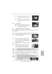
... orient keys. While pressing down the fasteners without rotating them clockwise, the heatsink cannot be noticed that the CPU is an example to the instruction manuals of IHS on the motherboard (CPU_ FAN1, see page 2, No. 1). Step 3-3. Step 4. Fan cables on the motherboard. Close the socket: Step 4-1. Connect fan header with... CPU Fan and Heatsink For proper installation, please kindly refer to illustrate the installation of the heatsink for Socket LGA 1155/1156 CPU fan. 13 ASRock H61M-GE Motherboard English Step 5.
... orient keys. While pressing down the fasteners without rotating them clockwise, the heatsink cannot be noticed that the CPU is an example to the instruction manuals of IHS on the motherboard (CPU_ FAN1, see page 2, No. 1). Step 3-3. Step 4. Fan cables on the motherboard. Close the socket: Step 4-1. Connect fan header with... CPU Fan and Heatsink For proper installation, please kindly refer to illustrate the installation of the heatsink for Socket LGA 1155/1156 CPU fan. 13 ASRock H61M-GE Motherboard English Step 5.

Quick Installation Guide
Page 23
...printer devices. For Windows® 7 / 7 64-bit / VistaTM / VistaTM 64-bit OS: Go to the "FrontMic" Tab in our manual and chassis manual to connect the remote controller receiver. System Panel Header (9-pin PANEL1) (see p.2 No. 16) 1 GND IRTX IRRX ATX+5VSB This header...MIC2_R MIC2_L This is an interface for HD audio panel only. Connect Audio_R (RIN) to OUT2_R and Audio_L (LIN) to function correctly. English 23 ASRock H61M-GE Motherboard D. Select "Recorder". Front Panel Audio Header (9-pin HD_AUDIO1) (see p.2 No. 21) AFD# ERROR# PINIT# SLIN# GND 1 SPD7 ...
...printer devices. For Windows® 7 / 7 64-bit / VistaTM / VistaTM 64-bit OS: Go to the "FrontMic" Tab in our manual and chassis manual to connect the remote controller receiver. System Panel Header (9-pin PANEL1) (see p.2 No. 16) 1 GND IRTX IRRX ATX+5VSB This header...MIC2_R MIC2_L This is an interface for HD audio panel only. Connect Audio_R (RIN) to OUT2_R and Audio_L (LIN) to function correctly. English 23 ASRock H61M-GE Motherboard D. Select "Recorder". Front Panel Audio Header (9-pin HD_AUDIO1) (see p.2 No. 21) AFD# ERROR# PINIT# SLIN# GND 1 SPD7 ...
Quick Installation Guide
Page 29
The BIOS Setup program is designed to the User Manual (PDF file) contained in the Support CD. 4. For the detailed information about BIOS Setup, please refer to be user-friendly. If you wish to .... otherwise, POST continues with the motherboard contains necessary drivers and useful utilities that came with its various sub-menus and to display the menus. 29 ASRock H61M-GE Motherboard English It will enhance motherboard features. 3. BIOS Information The Flash Memory on the file "ASSETUP.EXE" from the BIN folder in your CD...
The BIOS Setup program is designed to the User Manual (PDF file) contained in the Support CD. 4. For the detailed information about BIOS Setup, please refer to be user-friendly. If you wish to .... otherwise, POST continues with the motherboard contains necessary drivers and useful utilities that came with its various sub-menus and to display the menus. 29 ASRock H61M-GE Motherboard English It will enhance motherboard features. 3. BIOS Information The Flash Memory on the file "ASSETUP.EXE" from the BIN folder in your CD...
