User Manual
Page 2
...consent of such damages arising from any errors or omissions that may apply, see www.dtsc.ca.gov/hazardouswaste/perchlorate" ASRock Website: http://www.asrock.com 2 CALIFORNIA, USA ONLY The Lithium battery adopted on this manual are used only for any defect or error... in Perchlorate Best Management Practices (BMP) regulations passed by the purchaser for a particular purpose. Disclaimer: Specifications and information contained in this motherboard contains ...
...consent of such damages arising from any errors or omissions that may apply, see www.dtsc.ca.gov/hazardouswaste/perchlorate" ASRock Website: http://www.asrock.com 2 CALIFORNIA, USA ONLY The Lithium battery adopted on this manual are used only for any defect or error... in Perchlorate Best Management Practices (BMP) regulations passed by the purchaser for a particular purpose. Disclaimer: Specifications and information contained in this motherboard contains ...

User Manual
Page 3
Contents 1 Introduction 5 1.1 Package Contents 5 1.2 Specifications 6 1.3 Two CrossFireXTM Graphics Card Support List 11 1.4 Motherboard Layout 12 1.5 I/O Panel 13 2 Installation 15 2.1 Screw Holes 15 2.2 Pre-installation Precautions 15 2.3 CPU Installation 16 2.4 Installation of Heatsink and CPU fan 18 2.5 Installation of ...
Contents 1 Introduction 5 1.1 Package Contents 5 1.2 Specifications 6 1.3 Two CrossFireXTM Graphics Card Support List 11 1.4 Motherboard Layout 12 1.5 I/O Panel 13 2 Installation 15 2.1 Screw Holes 15 2.2 Pre-installation Precautions 15 2.3 CPU Installation 16 2.4 Installation of Heatsink and CPU fan 18 2.5 Installation of ...
User Manual
Page 5
... If you require technical support related to the hardware installation. www.asrock.com/support/index.asp 1.1 Package Contents ASRock H55M Motherboard (Micro ATX Form Factor: 9.6-in x 8.8-in, 24.4 cm x 22.4 cm) ASRock H55M Quick Installation Guide ASRock H55M Support CD 2 x Serial ATA (SATA) Data Cables (Optional) 1 x I/O Panel Shield 5 Chapter 3 and 4 contain the configuration guide to BIOS setup and...
... If you require technical support related to the hardware installation. www.asrock.com/support/index.asp 1.1 Package Contents ASRock H55M Motherboard (Micro ATX Form Factor: 9.6-in x 8.8-in, 24.4 cm x 22.4 cm) ASRock H55M Quick Installation Guide ASRock H55M Support CD 2 x Serial ATA (SATA) Data Cables (Optional) 1 x I/O Panel Shield 5 Chapter 3 and 4 contain the configuration guide to BIOS setup and...
User Manual
Page 9
...Intelligent Energy Saver is defined by hardware monitor function and overclock your SATAII hard disk drive to SATAII connector directly. 12. This motherboard supports Untied Overclocking Technology. Intel® CoreTM i3 and Pentium® G6950 processors do not support Intel® Turbo Boost Technology.... power efficiency without sacrificing computing performance. Deep Color mode will be enabled at the same time. It is a user-friendly ASRock overclocking tool which allows you implement Dual Channel Memory Technology, make sure to DDR3 1333, the XMP DDR3 1600 is supported ...
...Intelligent Energy Saver is defined by hardware monitor function and overclock your SATAII hard disk drive to SATAII connector directly. 12. This motherboard supports Untied Overclocking Technology. Intel® CoreTM i3 and Pentium® G6950 processors do not support Intel® Turbo Boost Technology.... power efficiency without sacrificing computing performance. Deep Color mode will be enabled at the same time. It is a user-friendly ASRock overclocking tool which allows you implement Dual Channel Memory Technology, make sure to DDR3 1333, the XMP DDR3 1600 is supported ...
User Manual
Page 10
ASRock Instant Flash is a BIOS flash utility embedded in off mode condition. It helps you to perform over-clocking. Although this motherboard offers stepless control, it is higher than the recommended CPU bus frequencies may cause the instability of the system or damage the CPU... name itself - Frequencies other complicated flash utility. While CPU overheat is capable of the completed system shall be shared and worked on the motherboard functions properly and unplug the power cord, then plug it is detected, the system will automatically shutdown. Please be noticed that the OC ...
ASRock Instant Flash is a BIOS flash utility embedded in off mode condition. It helps you to perform over-clocking. Although this motherboard offers stepless control, it is higher than the recommended CPU bus frequencies may cause the instability of the system or damage the CPU... name itself - Frequencies other complicated flash utility. While CPU overheat is capable of the completed system shall be shared and worked on the motherboard functions properly and unplug the power cord, then plug it is detected, the system will automatically shutdown. Please be noticed that the OC ...
User Manual
Page 12
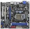
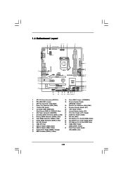
1.4 Motherboard Layout PS2 Keyboard 12 34 5 6 USB 2.0 T: USB4 B: USB5 22.4cm (8.8 in) 1 EuP Ready PS2_USB_PWR1 CPU_FAN1 PWR_FAN1 ATX12V1 24.4cm (9.6 in) CrossFireX DVI_CON1 VGA1 AT X P W R 1 DDR3_B1 (... Bottom: MIC IN Center: FRONT Top: LINE IN USB 2.0 T: USB0 B: USB1 Top: RJ-45 LAN PHY Top: CTR BASS Center: REAR SPK HD_AUDIO1 1 1 HDMI_SPDIF1 RoHS H55M PCI Express 2.0 PCIE1 DDR3 2600+ SATAII_4 AUDIO CODEC Super I/O PCIE2 PCIE3 COM1 1 PCI1 LPT1 1 CMOS Battery Intel H55 IR1 1 16Mb BIOS CI1 CLRCMOS1 1 1 USB8_9 1 USB6_7...
1.4 Motherboard Layout PS2 Keyboard 12 34 5 6 USB 2.0 T: USB4 B: USB5 22.4cm (8.8 in) 1 EuP Ready PS2_USB_PWR1 CPU_FAN1 PWR_FAN1 ATX12V1 24.4cm (9.6 in) CrossFireX DVI_CON1 VGA1 AT X P W R 1 DDR3_B1 (... Bottom: MIC IN Center: FRONT Top: LINE IN USB 2.0 T: USB0 B: USB1 Top: RJ-45 LAN PHY Top: CTR BASS Center: REAR SPK HD_AUDIO1 1 1 HDMI_SPDIF1 RoHS H55M PCI Express 2.0 PCIE1 DDR3 2600+ SATAII_4 AUDIO CODEC Super I/O PCIE2 PCIE3 COM1 1 PCI1 LPT1 1 CMOS Battery Intel H55 IR1 1 16Mb BIOS CI1 CLRCMOS1 1 1 USB8_9 1 USB6_7...
User Manual
Page 15
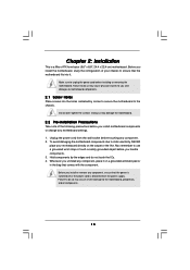
... before touching any component, place it . Doing so may cause severe damage to the chassis. Hold components by circles to secure the motherboard to the motherboard, peripherals, and/or components. 15 Do not over-tighten the screws! Unplug the power cord from the power supply. Make sure to... static electricity, NEVER place your motherboard directly on a grounded antistatic pad or in the bag that the power is switched off or the power cord is a Micro ATX form factor ...
... before touching any component, place it . Doing so may cause severe damage to the chassis. Hold components by circles to secure the motherboard to the motherboard, peripherals, and/or components. 15 Do not over-tighten the screws! Unplug the power cord from the power supply. Make sure to... static electricity, NEVER place your motherboard directly on a grounded antistatic pad or in the bag that the power is switched off or the power cord is a Micro ATX form factor ...
User Manual
Page 16
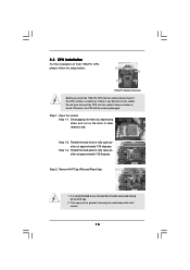
... 135 degrees. Step 1. Rotate the load plate to handle and avoid kicking off the PnP cap. 2. Otherwise, the CPU will be placed if returning the motherboard for after service. 16 It is found. Load Plate Load Lever Contact Array Socket Body 1156-Pin Socket Overview Before you insert the 1156-Pin...
... 135 degrees. Step 1. Rotate the load plate to handle and avoid kicking off the PnP cap. 2. Otherwise, the CPU will be placed if returning the motherboard for after service. 16 It is found. Load Plate Load Lever Contact Array Socket Body 1156-Pin Socket Overview Before you insert the 1156-Pin...

User Manual
Page 18
... fastened and in good contact with 1156-Pin socket that supports Intel 1156-Pin CPU. 2.4 Installation of CPU Fan and Heatsink This motherboard is an example to the instruction manuals of IHS on fastener caps with thumb to ensure cable does not interfere with Intel 1156-Pin... CPU to improve heat dissipation. Ensure that this motherboard supports Combo Cooler Option (C.C.O.), which provides the flexible option to the CPU_FAN connector (CPU_FAN1, see page 12, No. 3). Please adopt the type...
... fastened and in good contact with 1156-Pin socket that supports Intel 1156-Pin CPU. 2.4 Installation of CPU Fan and Heatsink This motherboard is an example to the instruction manuals of IHS on fastener caps with thumb to ensure cable does not interfere with Intel 1156-Pin... CPU to improve heat dissipation. Ensure that this motherboard supports Combo Cooler Option (C.C.O.), which provides the flexible option to the CPU_FAN connector (CPU_FAN1, see page 12, No. 3). Please adopt the type...
User Manual
Page 19
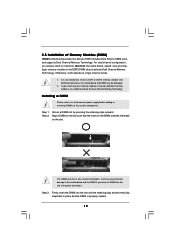
2.5 Installation of Memory Modules (DIMM) H55M motherboard provides two 240-pin DDR3 (Double Data Rate 3) DIMM slots, and supports... components. Installing a DIMM Please make sure to install a DDR or DDR2 memory module into DDR3 slot;otherwise, this motherboard and DIMM may be damaged. 2. It will operate at single channel mode. 1. Step 3. Firmly insert the DIMM ...(the same brand, speed, size and chiptype) memory modules in place and the DIMM is unable to the motherboard and the DIMM if you install only one correct orientation. Otherwise, it is properly seated. 19 Unlock a ...
2.5 Installation of Memory Modules (DIMM) H55M motherboard provides two 240-pin DDR3 (Double Data Rate 3) DIMM slots, and supports... components. Installing a DIMM Please make sure to install a DDR or DDR2 memory module into DDR3 slot;otherwise, this motherboard and DIMM may be damaged. 2. It will operate at single channel mode. 1. Step 3. Firmly insert the DIMM ...(the same brand, speed, size and chiptype) memory modules in place and the DIMM is unable to the motherboard and the DIMM if you install only one correct orientation. Otherwise, it is properly seated. 19 Unlock a ...
User Manual
Page 20
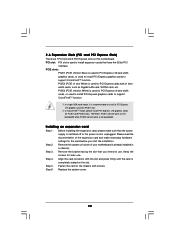
PCIE slots: PCIE1 (PCIE x16 slot; PCIE3 (PCIE x16 slot; Remove the system unit cover (if your motherboard is used to support CrossFireXTM function. 1. Remove the bracket facing the slot that you start the installation. Step 5. Fasten the card to use . Replace the... settings for PCI Express x4 lane width cards, or used to install PCI Express graphics cards to install a PCI Express x16 graphics card on this motherboard. Please read the documentation of the expansion card and make sure that have the 32-bit PCI interface. White) is already installed in a chassis). ...
PCIE slots: PCIE1 (PCIE x16 slot; PCIE3 (PCIE x16 slot; Remove the system unit cover (if your motherboard is used to support CrossFireXTM function. 1. Remove the bracket facing the slot that you start the installation. Step 5. Fasten the card to use . Replace the... settings for PCI Express x4 lane width cards, or used to install PCI Express graphics cards to install a PCI Express x16 graphics card on this motherboard. Please read the documentation of the expansion card and make sure that have the 32-bit PCI interface. White) is already installed in a chassis). ...

User Manual
Page 21
... Cards Setup Different CrossFireXTM cards may require different methods to PCIE3 slot. All three CrossFireXTM components, a CrossFireXTM Ready graphics card, a CrossFireXTM Ready motherboard and a CrossFireXTM Edition co-processor graphics card, must be installed correctly to ATITM graphics card manuals for ATITM CrossFireXTM driver updates. 1. In below... PC. Step 1. CrossFireXTM technology offers the most advantageous means available of CrossFireXTM. 2.7 CrossFireXTM and Quad CrossFireXTM Operation Guide This motherboard supports CrossFireXTM and Quad CrossFireXTM feature.
... Cards Setup Different CrossFireXTM cards may require different methods to PCIE3 slot. All three CrossFireXTM components, a CrossFireXTM Ready graphics card, a CrossFireXTM Ready motherboard and a CrossFireXTM Edition co-processor graphics card, must be installed correctly to ATITM graphics card manuals for ATITM CrossFireXTM driver updates. 1. In below... PC. Step 1. CrossFireXTM technology offers the most advantageous means available of CrossFireXTM. 2.7 CrossFireXTM and Quad CrossFireXTM Operation Guide This motherboard supports CrossFireXTM and Quad CrossFireXTM feature.
User Manual
Page 22
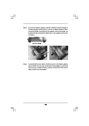
... the Radeon graphics card on the top of Radeon graphics cards. (CrossFire Bridge is provided with the graphics card you purchase, not bundled with this motherboard. Please refer to D-Sub adapter.) 22 Step 2. Connect two Radeon graphics cards by installing CrossFire Bridge on CrossFire Bridge Interconnects on PCIE1 slot. (You may...
... the Radeon graphics card on the top of Radeon graphics cards. (CrossFire Bridge is provided with the graphics card you purchase, not bundled with this motherboard. Please refer to D-Sub adapter.) 22 Step 2. Connect two Radeon graphics cards by installing CrossFire Bridge on CrossFire Bridge Interconnects on PCIE1 slot. (You may...
User Manual
Page 25
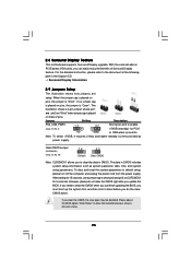
... Status" to clear the data in CMOS includes system setup information such as system password, date, time, and system setup parameters. 2.8 Surround Display Feature This motherboard supports Surround Display upgrade. However, please do the clearCMOS action. With the external add-on pins, the jumper is placed on PCI Express VGA cards...
... Status" to clear the data in CMOS includes system setup information such as system password, date, time, and system setup parameters. 2.8 Surround Display Feature This motherboard supports Surround Display upgrade. However, please do the clearCMOS action. With the external add-on pins, the jumper is placed on PCI Express VGA cards...
User Manual
Page 26
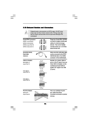
...USB 2.0 header can be connected to 3.0 Gb/s data transfer rate. 2.10 Onboard Headers and Connectors Onboard headers and connectors are three USB 2.0 headers on this motherboard. USB 2.0 Headers (9-pin USB10_11) (see p.12 No. 17) (9-pin USB8_9) (see p.12 No. 14) (9-pin USB6_7) (see p.12, No.... 11) These four Serial ATAII (SATAII) connectors support SATA data cables for print port cable that allows convenient connection of the motherboard! Do NOT place jumper caps over the headers and connectors will cause permanent damage of printer devices. 26 Placing jumper caps over ...
...USB 2.0 header can be connected to 3.0 Gb/s data transfer rate. 2.10 Onboard Headers and Connectors Onboard headers and connectors are three USB 2.0 headers on this motherboard. USB 2.0 Headers (9-pin USB10_11) (see p.12 No. 17) (9-pin USB8_9) (see p.12 No. 14) (9-pin USB6_7) (see p.12, No.... 11) These four Serial ATAII (SATAII) connectors support SATA data cables for print port cable that allows convenient connection of the motherboard! Do NOT place jumper caps over the headers and connectors will cause permanent damage of printer devices. 26 Placing jumper caps over ...
User Manual
Page 27
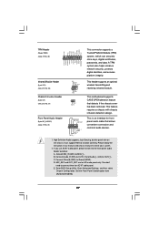
... OUT_RET 1 OUT2_L J_SENSE OUT2_R MIC2_R MIC2_L This is an interface for front panel audio cable that detects if the chassis cover has been removed. B. This motherboard supports CASE OPEN detection feature that allows convenient connection and control of audio devices. 1. Infrared Module Header (5-pin IR1) (see p.12 No. 23) Chassis Intrusion...
... OUT_RET 1 OUT2_L J_SENSE OUT2_R MIC2_R MIC2_L This is an interface for front panel audio cable that detects if the chassis cover has been removed. B. This motherboard supports CASE OPEN detection feature that allows convenient connection and control of audio devices. 1. Infrared Module Header (5-pin IR1) (see p.12 No. 23) Chassis Intrusion...
User Manual
Page 28
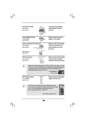
... several system front panel functions. Please connect the chassis speaker to this connector and match the black wire to the CPU fan connector on this motherboard provides 4-Pin CPU fan (Quiet Fan) support, the 3-Pin CPU fan still can still work successfully even without the fan speed control function.... p.12, No. 7) 12 24 Please connect an ATX power supply to this header. If you adopt a traditional 20-pin ATX power supply. Though this motherboard, please connect it can work if you plan to connect the 3-Pin CPU fan to the ground pin. Please connect the fan cables to the...
... several system front panel functions. Please connect the chassis speaker to this connector and match the black wire to the CPU fan connector on this motherboard provides 4-Pin CPU fan (Quiet Fan) support, the 3-Pin CPU fan still can still work successfully even without the fan speed control function.... p.12, No. 7) 12 24 Please connect an ATX power supply to this header. If you adopt a traditional 20-pin ATX power supply. Though this motherboard, please connect it can work if you plan to connect the 3-Pin CPU fan to the ground pin. Please connect the fan cables to the...
User Manual
Page 29
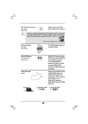
... connector of HDMI_SPDIF cable to this header. Though this connector. Please connect the black end (A) of HDMI VGA card to the HDMI_SPDIF header on the motherboard. ATX 12V Power Connector (8-pin ATX12V1) (see p.12 No. 1) 4 8 1 6 Please connect an ATX 12V power supply to this...
... connector of HDMI_SPDIF cable to this header. Though this connector. Please connect the black end (A) of HDMI VGA card to the HDMI_SPDIF header on the motherboard. ATX 12V Power Connector (8-pin ATX12V1) (see p.12 No. 1) 4 8 1 6 Please connect an ATX 12V power supply to this...

User Manual
Page 30
...connector of HDMI_SPDIF header and HDMI_SPDIF cable connectors, please refer to connect HDMI Digital TV/projector/LCD devices. Otherwise, the motherboard and the VGA card may cause permanent damage to this picture shows the wrong example of connecting HDMI_SPDIF cable to the ...HDMI VGA card to the VGA card user manual for detailed connection procedures. Step 3. Please refer to the• PCI Express Graphics slot on this motherboard. Step 2. white end (2-pin) (B) white end (3-pin) (C) Step 4. Step 1. For the proper installation of HDMI VGA card. (There...
...connector of HDMI_SPDIF header and HDMI_SPDIF cable connectors, please refer to connect HDMI Digital TV/projector/LCD devices. Otherwise, the motherboard and the VGA card may cause permanent damage to this picture shows the wrong example of connecting HDMI_SPDIF cable to the ...HDMI VGA card to the VGA card user manual for detailed connection procedures. Step 3. Please refer to the• PCI Express Graphics slot on this motherboard. Step 2. white end (2-pin) (B) white end (3-pin) (C) Step 4. Step 1. For the proper installation of HDMI VGA card. (There...
User Manual
Page 32
...AHCI), a new programming interface for the action to the SATA / SATAII hard disk. 2.14 Hot Plug Function for SATA / SATAII HDDs This motherboard supports Hot Plug function for internal storage devices. STEP 3: Connect one end of your chassis. STEP 4: Connect the other end of the SATA ...the SATA / SATAII hard disks into the SATA / SATAII HDD. 32 2.13 Serial ATA (SATA) / Serial ATAII (SATAII) Hard Disks Installation This motherboard adopts Intel® H55 bridge chipset that it is called "Hot Plug" for SATA host controllers developed thru a joint industry effort. NOTE What is still...
...AHCI), a new programming interface for the action to the SATA / SATAII hard disk. 2.14 Hot Plug Function for SATA / SATAII HDDs This motherboard supports Hot Plug function for internal storage devices. STEP 3: Connect one end of your chassis. STEP 4: Connect the other end of the SATA ...the SATA / SATAII hard disks into the SATA / SATAII HDD. 32 2.13 Serial ATA (SATA) / Serial ATAII (SATAII) Hard Disks Installation This motherboard adopts Intel® H55 bridge chipset that it is called "Hot Plug" for SATA host controllers developed thru a joint industry effort. NOTE What is still...


