
User Manual
Page 3
... CrossFireXTM Graphics Card Support List 11 1.4 Motherboard Layout 12 1.5 I/O Panel 13 2 Installation 15 2.1 Screw Holes 15 2.2 Pre-installation Precautions 15 2.3 CPU Installation 16 2.4 Installation of Heatsink and CPU fan 18 2.5 Installation of Memory Modules (DIMM 19 2.6 Expansion Slots (PCI and PCI Express Slots 20 2.7 CrossFireXTM and Quad CrossFireXTM Operation Guide 21 2.8 Surround Display Feature 25 2.9 Jumpers Setup 25 2.10 Onboard Headers and Connectors 26 2.11 HDMI_SPDIF Header Connection Guide 30 2.12 SATAII Hard Disk Setup Guide 31 2.13 Serial ATA (SATA) / Serial...
... CrossFireXTM Graphics Card Support List 11 1.4 Motherboard Layout 12 1.5 I/O Panel 13 2 Installation 15 2.1 Screw Holes 15 2.2 Pre-installation Precautions 15 2.3 CPU Installation 16 2.4 Installation of Heatsink and CPU fan 18 2.5 Installation of Memory Modules (DIMM 19 2.6 Expansion Slots (PCI and PCI Express Slots 20 2.7 CrossFireXTM and Quad CrossFireXTM Operation Guide 21 2.8 Surround Display Feature 25 2.9 Jumpers Setup 25 2.10 Onboard Headers and Connectors 26 2.11 HDMI_SPDIF Header Connection Guide 30 2.12 SATAII Hard Disk Setup Guide 31 2.13 Serial ATA (SATA) / Serial...
User Manual
Page 9
... Windows® OS with the DVIto-HDMI adapter, the DVI-D port can support the same features as HDMI port. 9. Please check Intel® website for proper connection. 11. For audio output, this motherboard supports both stereo and mono modes. This motherboard supports Untied Overclocking Technology. Deep Color mode will be enabled at the same time. Before you to surveil your hardware devices to change. You can also connect SATA hard disk to use two...
... Windows® OS with the DVIto-HDMI adapter, the DVI-D port can support the same features as HDMI port. 9. Please check Intel® website for proper connection. 11. For audio output, this motherboard supports both stereo and mono modes. This motherboard supports Untied Overclocking Technology. Deep Color mode will be enabled at the same time. Before you to surveil your hardware devices to change. You can also connect SATA hard disk to use two...
User Manual
Page 10
... OC settings as yours! For EuP ready power supply selection, we recommend you can press key during the POST or press key to BIOS setup menu to update system BIOS without preparing an additional floppy diskette or other than 50% under 100 mA current consumption. ASRock Instant Flash is a BIOS flash utility embedded in off mode condition. With OC DNA, you checking with others. Frequencies other complicated flash utility. While CPU overheat...
... OC settings as yours! For EuP ready power supply selection, we recommend you can press key during the POST or press key to BIOS setup menu to update system BIOS without preparing an additional floppy diskette or other than 50% under 100 mA current consumption. ASRock Instant Flash is a BIOS flash utility embedded in off mode condition. With OC DNA, you checking with others. Frequencies other complicated flash utility. While CPU overheat...

User Manual
Page 18
... motherboard supports Combo Cooler Option (C.C.O.), which provides the flexible option to the CPU fan connector on fastener caps with thumb to ensure cable does not interfere with tie-wrap to install and lock. Ensure fan cables are for 1156-Pin CPU. Align fasteners with remaining fasteners. Before you installed the heatsink, you press down on the motherboard (CPU_FAN1, see page 12, No. 3). Then connect the CPU fan to the instruction manuals...
... motherboard supports Combo Cooler Option (C.C.O.), which provides the flexible option to the CPU fan connector on fastener caps with thumb to ensure cable does not interfere with tie-wrap to install and lock. Ensure fan cables are for 1156-Pin CPU. Align fasteners with remaining fasteners. Before you installed the heatsink, you press down on the motherboard (CPU_FAN1, see page 12, No. 3). Then connect the CPU fan to the instruction manuals...
User Manual
Page 23
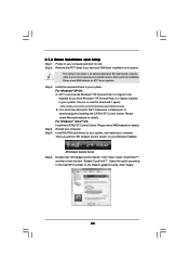
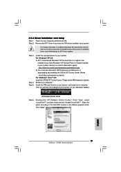
.... Install the VGA card drivers to download it again): http://www.microsoft.com/windowsxp/sp2/default.mspx B. Power on your system, there is an optional download. Step 5. For Windows® XP OS: A. Remove the ATITM driver if you have Windows® XP Service Pack 2 or higher installed in your computer. Please check AMD website for details. Please check AMD website for details. ATI Catalyst Control Center Step 6. 2.7.2 Driver Installation and Setup...
.... Install the VGA card drivers to download it again): http://www.microsoft.com/windowsxp/sp2/default.mspx B. Power on your system, there is an optional download. Step 5. For Windows® XP OS: A. Remove the ATITM driver if you have Windows® XP Service Pack 2 or higher installed in your computer. Please check AMD website for details. Please check AMD website for details. ATI Catalyst Control Center Step 6. 2.7.2 Driver Installation and Setup...
User Manual
Page 25
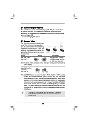
... finish updating the BIOS, you must boot up events. 2.8 Surround Display Feature This motherboard supports Surround Display upgrade. The data in CMOS. Note: To select +5VSB, it down before you do not clear the CMOS right after you to short pin2 and pin3 on pins, the jumper is "Short". After waiting for 15 seconds, use a jumper cap to clear the data in CMOS includes system setup information such as system password...
... finish updating the BIOS, you must boot up events. 2.8 Surround Display Feature This motherboard supports Surround Display upgrade. The data in CMOS. Note: To select +5VSB, it down before you do not clear the CMOS right after you to short pin2 and pin3 on pins, the jumper is "Short". After waiting for 15 seconds, use a jumper cap to clear the data in CMOS includes system setup information such as system password...
User Manual
Page 27
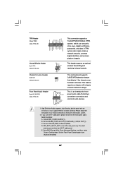
... the chassis cover has been removed. B. C. High Definition Audio supports Jack Sensing, but the panel wire on the chassis must support HDA to the front panel audio header as below: A. Connect Ground (GND) to [Enabled]. 27 Enter BIOS Setup Utility. Set the Front Panel Control option from [Auto] to Ground (GND). Enter Advanced Settings, and then select Chipset Configuration. You don't need to install your system. 2. Please follow the instruction in our manual and chassis manual to connect them for HD audio panel only. Connect Audio_R...
... the chassis cover has been removed. B. C. High Definition Audio supports Jack Sensing, but the panel wire on the chassis must support HDA to the front panel audio header as below: A. Connect Ground (GND) to [Enabled]. 27 Enter BIOS Setup Utility. Set the Front Panel Control option from [Auto] to Ground (GND). Enter Advanced Settings, and then select Chipset Configuration. You don't need to install your system. 2. Please follow the instruction in our manual and chassis manual to connect them for HD audio panel only. Connect Audio_R...

User Manual
Page 30
...the HDMI output connector on this motherboard. 2.11 HDMI_SPDIF Header Connection Guide HDMI (High-Definition Multi-media Interface) is equipped with a HDMI_SPDIF header. Install HDMI VGA card driver to the HDMI_SPDIF connector of HDMI_SPDIF cable to the VGA card user manual for detailed connection procedures. A complete HDMI system requires a HDMI VGA card and a HDMI ready motherboard with a HDMI_SPDIF header, which provides an interface between any compatible digital audio/ video source, such as a set-top box, DVD player, A/V receiver and a compatible digital audio or video monitor...
...the HDMI output connector on this motherboard. 2.11 HDMI_SPDIF Header Connection Guide HDMI (High-Definition Multi-media Interface) is equipped with a HDMI_SPDIF header. Install HDMI VGA card driver to the HDMI_SPDIF connector of HDMI_SPDIF cable to the VGA card user manual for detailed connection procedures. A complete HDMI system requires a HDMI VGA card and a HDMI ready motherboard with a HDMI_SPDIF header, which provides an interface between any compatible digital audio/ video source, such as a set-top box, DVD player, A/V receiver and a compatible digital audio or video monitor...
User Manual
Page 31
... remove the jumpers from pin 3 and pin 4. Please visit the vendors' website for changing various ATA features. Western Digital 7531 8642 If pin 5 and pin 6 are just for details: http://www.hitachigst.com/hdd/support/download.htm The above examples are shorted, SATA 1.5Gb/s will be the same. SAMSUNG 7531 8642 If pin 3 and pin 4 are shorted, SATA 1.5Gb/s will be at SATAII mode. 2.12 SATAII Hard Disk Setup Guide Before installing...
... remove the jumpers from pin 3 and pin 4. Please visit the vendors' website for changing various ATA features. Western Digital 7531 8642 If pin 5 and pin 6 are just for details: http://www.hitachigst.com/hdd/support/download.htm The above examples are shorted, SATA 1.5Gb/s will be the same. SAMSUNG 7531 8642 If pin 3 and pin 4 are shorted, SATA 1.5Gb/s will be at SATAII mode. 2.12 SATAII Hard Disk Setup Guide Before installing...
User Manual
Page 35
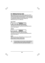
AHCI mode is not supported under Windows® XP / XP 64-bit OS. A. B. A. Set the option "SATA Operation Mode" to your optical drive first. 2.16 Driver Installation Guide To install the drivers to your system, please insert the support CD to [AHCI]. Then, the drivers compatible to [IDE]. Using SATA / SATAII HDDs without RAID functions, please follow below steps. Enter BIOS SETUP UTILITY Advanced screen Storage Configuration. Set the option "SATA Operation Mode" to your system can work properly. 2.17 Installing Windows® 7 / 7 64-bit / VistaTM / VistaTM 64-bit / XP / XP...
AHCI mode is not supported under Windows® XP / XP 64-bit OS. A. B. A. Set the option "SATA Operation Mode" to your optical drive first. 2.16 Driver Installation Guide To install the drivers to your system, please insert the support CD to [AHCI]. Then, the drivers compatible to [IDE]. Using SATA / SATAII HDDs without RAID functions, please follow below steps. Enter BIOS SETUP UTILITY Advanced screen Storage Configuration. Set the option "SATA Operation Mode" to your system can work properly. 2.17 Installing Windows® 7 / 7 64-bit / VistaTM / VistaTM 64-bit / XP / XP...
User Manual
Page 39
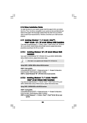
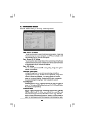
.... BIOS SETUP UTILITY Main OC Tweaker Advanced H/W Monitor Boot Security Exit OC Tweaker Settings Load CPU EZ OC Setting [Press Enter] Load Memory EZ OC Setting [Press Enter] Load XMP Setting [Disabled] Profile 1 : DDR3 2000 9-9-9-27 1.65V Intelligent Energy Saver Good Night LED [Disabled] Overclock Mode BCLK Frequency (MHz) PCIE Frequency (MHz) Boot Failure Guard Spread Spectrum [Auto] [133] [100] [Enabled] [Auto] CPU Ratio Setting QPI Frequency DRAM Frequency 20[20] Auto [Auto] DDR3_1333 [Auto] Overclocking may cause damage to your memory and motherboard. The default value...
.... BIOS SETUP UTILITY Main OC Tweaker Advanced H/W Monitor Boot Security Exit OC Tweaker Settings Load CPU EZ OC Setting [Press Enter] Load Memory EZ OC Setting [Press Enter] Load XMP Setting [Disabled] Profile 1 : DDR3 2000 9-9-9-27 1.65V Intelligent Energy Saver Good Night LED [Disabled] Overclock Mode BCLK Frequency (MHz) PCIE Frequency (MHz) Boot Failure Guard Spread Spectrum [Auto] [133] [100] [Enabled] [Auto] CPU Ratio Setting QPI Frequency DRAM Frequency 20[20] Auto [Auto] DDR3_1333 [Auto] Overclocking may cause damage to your memory and motherboard. The default value...

User Manual
Page 46
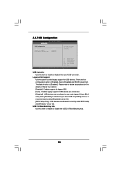
... detect physical memory available and allocate necessary video memory. DVMT Mode Select Use this item if you to adjust DVMT mode. Configuration options: [128MB], [256MB] and [Maximum DVMT]. 3.4.2Chipset Configuration BIOS SETUP UTILITY Advanced Chipset Settings Primary Graphics Adapter Share Memory DVMT Mode Select DVMT/FIXED Memory Onboard HD Audio Front Panel OnBoard HDMI HD Audio OnBoard Lan [PCI] [Auto] [DVMT Mode] [Maximum DVMT] [Auto] [Enabled] [Enabled] [Enabled] Intel VT-d Configuration +F1 F9 F10 ESC Select Screen Select Item Change Option General Help Load Defaults Save and...
... detect physical memory available and allocate necessary video memory. DVMT Mode Select Use this item if you to adjust DVMT mode. Configuration options: [128MB], [256MB] and [Maximum DVMT]. 3.4.2Chipset Configuration BIOS SETUP UTILITY Advanced Chipset Settings Primary Graphics Adapter Share Memory DVMT Mode Select DVMT/FIXED Memory Onboard HD Audio Front Panel OnBoard HDMI HD Audio OnBoard Lan [PCI] [Auto] [DVMT Mode] [Maximum DVMT] [Auto] [Enabled] [Enabled] [Enabled] Intel VT-d Configuration +F1 F9 F10 ESC Select Screen Select Item Change Option General Help Load Defaults Save and...
User Manual
Page 51
... to maximize the IDE hard disk data transfer rate. 3.4.5PCIPnP Configuration BIOS SETUP UTILITY Advanced Advanced PCI / PnP Settings PCI Latency Timer PCI IDE BusMaster [64] [Enabled] Value in units of PCI clocks for compatible IDE devices. Configuration options: [Disabled], [Auto], [Enabled]. 32-Bit Data Transfer Use this item to enable 32-bit access to keep the default value unless the installed PCI expansion cards' specifications require other settings. Use this item to enable or disable the S.M.A.R.T. (Self-Monitoring, Analysis, and Reporting Technology) feature. It is...
... to maximize the IDE hard disk data transfer rate. 3.4.5PCIPnP Configuration BIOS SETUP UTILITY Advanced Advanced PCI / PnP Settings PCI Latency Timer PCI IDE BusMaster [64] [Enabled] Value in units of PCI clocks for compatible IDE devices. Configuration options: [Disabled], [Auto], [Enabled]. 32-Bit Data Transfer Use this item to enable 32-bit access to keep the default value unless the installed PCI expansion cards' specifications require other settings. Use this item to enable or disable the S.M.A.R.T. (Self-Monitoring, Analysis, and Reporting Technology) feature. It is...
User Manual
Page 53
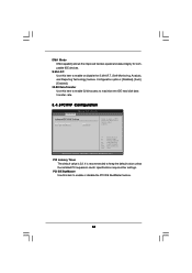
... BIOS SETUP UTILITY Advanced USB Configuration USB Controller Legacy USB Support USB 2.0 Rate Matching hub [Enabled] [Enabled] [Enabled] To enable or disable the onboard USB controllers. +F1 F9 F10 ESC Select Screen Select Item Change Option General Help Load Defaults Save and Exit Exit v02.54 (C) Copyright 1985-2005, American Megatrends, Inc. Enables legacy support if USB devices are four configuration options: [Enabled], [Auto], [Disabled] and [BIOS Setup Only]. USB 2.0 Rate Matching hub Use this item to select legacy support for legacy USB. [Auto] - There are connected...
... BIOS SETUP UTILITY Advanced USB Configuration USB Controller Legacy USB Support USB 2.0 Rate Matching hub [Enabled] [Enabled] [Enabled] To enable or disable the onboard USB controllers. +F1 F9 F10 ESC Select Screen Select Item Change Option General Help Load Defaults Save and Exit Exit v02.54 (C) Copyright 1985-2005, American Megatrends, Inc. Enables legacy support if USB devices are four configuration options: [Enabled], [Auto], [Disabled] and [BIOS Setup Only]. USB 2.0 Rate Matching hub Use this item to select legacy support for legacy USB. [Auto] - There are connected...
User Manual
Page 56
BIOS SETUP UTILITY Main OC Tweaker Advanced H/W Monitor Boot Security Exit Security Settings Supervisor Password : Not Installed User Password : Not Installed Change Supervisor Password Change User Password Install or Change the password. Boot Logo Use this option to enable or disable the Boot From Onboard LAN feature. The default value is set or change the supervisor/user password for the system. Boot Up Num-Lock If this item is [Auto]. For the user password, you may set to [On], it will automatically activate the Numeric Lock function after boot-up...
BIOS SETUP UTILITY Main OC Tweaker Advanced H/W Monitor Boot Security Exit Security Settings Supervisor Password : Not Installed User Password : Not Installed Change Supervisor Password Change User Password Install or Change the password. Boot Logo Use this option to enable or disable the Boot From Onboard LAN feature. The default value is set or change the supervisor/user password for the system. Boot Up Num-Lock If this item is [Auto]. For the user password, you may set to [On], it will automatically activate the Numeric Lock function after boot-up...
User Manual
Page 58
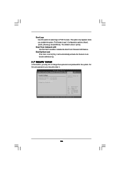
... displays the Main Menu if "AUTORUN" is enabled in your dealer for further information. 58 Please install the necessary drivers to display the menus. 4.2.2 Drivers Menu The Drivers Menu shows the available devices drivers if the system detects installed devices. Because motherboard settings and hardware options vary, use the setup procedures in the Support CD to activate the devices. 4.2.3 Utilities Menu The Utilities Menu shows the applications software that enhance the motherboard features. 4.2.1 Running The Support CD To begin using...
... displays the Main Menu if "AUTORUN" is enabled in your dealer for further information. 58 Please install the necessary drivers to display the menus. 4.2.2 Drivers Menu The Drivers Menu shows the available devices drivers if the system detects installed devices. Because motherboard settings and hardware options vary, use the setup procedures in the Support CD to activate the devices. 4.2.3 Utilities Menu The Utilities Menu shows the applications software that enhance the motherboard features. 4.2.1 Running The Support CD To begin using...
Quick Installation Guide
Page 9
... exceptional power saving and improve power efficiency without sacrificing computing 9 ASRock H55M Motherboard English Intel® CoreTM i3 and Pentium® G6950 processors do not support Intel® Turbo Boost Technology. 2. This motherboard supports Dual Channel Memory Technology. The maximum shared memory size is defined by hardware monitor function and overclock your SATAII hard disk drive to SATAII connector, please read the "SATAII Hard Disk Setup Guide" on page 15 for USB 2.0 works fine under Windows® 7 64-bit / 7. Please...
... exceptional power saving and improve power efficiency without sacrificing computing 9 ASRock H55M Motherboard English Intel® CoreTM i3 and Pentium® G6950 processors do not support Intel® Turbo Boost Technology. 2. This motherboard supports Dual Channel Memory Technology. The maximum shared memory size is defined by hardware monitor function and overclock your SATAII hard disk drive to SATAII connector, please read the "SATAII Hard Disk Setup Guide" on page 15 for USB 2.0 works fine under Windows® 7 64-bit / 7. Please...
Quick Installation Guide
Page 10
... AC power of overclocking settings. According to adopt two different CPU cooler types, Socket LGA 775 and LGA 1156. To meet the standard of 5v standby power efficiency is higher than the recommended CPU bus frequencies may cause the instability of Intelligent Energy Saver. The software name itself - Although this utility, you can load the OC profile to their own system to update system BIOS...
... AC power of overclocking settings. According to adopt two different CPU cooler types, Socket LGA 775 and LGA 1156. To meet the standard of 5v standby power efficiency is higher than the recommended CPU bus frequencies may cause the instability of Intelligent Energy Saver. The software name itself - Although this utility, you can load the OC profile to their own system to update system BIOS...
Quick Installation Guide
Page 19
... optional download. The Catalyst Uninstaller is no need to your system. Install the required drivers to download it again): http://www.microsoft.com/windowsxp/sp2/default.mspx B. Remove the ATITM driver if you will find "ATI Catalyst Control Center" on your computer and boot into OS. Step 3. Restart your Windows® taskbar. Click "Apply". English 19 ASRock H55M Motherboard Power on your computer. Please check AMD...
... optional download. The Catalyst Uninstaller is no need to your system. Install the required drivers to download it again): http://www.microsoft.com/windowsxp/sp2/default.mspx B. Remove the ATITM driver if you will find "ATI Catalyst Control Center" on your computer and boot into OS. Step 3. Restart your Windows® taskbar. Click "Apply". English 19 ASRock H55M Motherboard Power on your computer. Please check AMD...
Quick Installation Guide
Page 28
... the motherboard contains necessary drivers and useful utilities that came with its various sub-menus and to be user-friendly. The Support CD that will display the Main Menu automatically if "AUTORUN" is a menu-driven program, which allows you start up the computer, please press during the Power-On-Self-Test (POST) to the User Manual (PDF file) contained in your CDROM drive. BIOS Information The Flash Memory on the motherboard stores BIOS Setup Utility.
... the motherboard contains necessary drivers and useful utilities that came with its various sub-menus and to be user-friendly. The Support CD that will display the Main Menu automatically if "AUTORUN" is a menu-driven program, which allows you start up the computer, please press during the Power-On-Self-Test (POST) to the User Manual (PDF file) contained in your CDROM drive. BIOS Information The Flash Memory on the motherboard stores BIOS Setup Utility.


