User Manual
Page 10
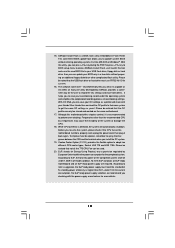
Just launch this tool and save the new BIOS file to access ASRock Instant Flash. To improve heat dissipation, remember to adopt two different CPU cooler types, Socket LGA 775 and LGA 1156. To meet the standard of 5v standby power efficiency is capable of the completed system shall be ... in a few clicks without entering operating systems first like MS-DOS or Windows®. According to record the OC settings and share with others. ASRock Instant Flash is a BIOS flash utility embedded in Flash ROM. Please be used. 20. OC DNA, an exclusive utility developed by European Union to...
Just launch this tool and save the new BIOS file to access ASRock Instant Flash. To improve heat dissipation, remember to adopt two different CPU cooler types, Socket LGA 775 and LGA 1156. To meet the standard of 5v standby power efficiency is capable of the completed system shall be ... in a few clicks without entering operating systems first like MS-DOS or Windows®. According to record the OC settings and share with others. ASRock Instant Flash is a BIOS flash utility embedded in Flash ROM. Please be used. 20. OC DNA, an exclusive utility developed by European Union to...
User Manual
Page 12
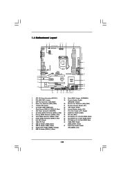
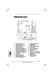
...FRONT Top: LINE IN USB 2.0 T: USB0 B: USB1 Top: RJ-45 LAN PHY Top: CTR BASS Center: REAR SPK HD_AUDIO1 1 1 HDMI_SPDIF1 RoHS H55M PCI Express 2.0 PCIE1 DDR3 2600+ SATAII_4 AUDIO CODEC Super I/O PCIE2 PCIE3 COM1 1 PCI1 LPT1 1 CMOS Battery Intel H55 IR1 1 16Mb BIOS CI1 ... Jumper 19 Chassis Speaker Header 3 CPU Fan Connector (CPU_FAN1) (SPEAKER 1, Purple) 4 Power Fan Connector (PWR_FAN1) 20 Chassis Fan Connector (CHA_FAN1) 5 1156-Pin CPU Socket 21 Chassis Intrusion Header (CI1) 6 2 x 240-pin DDR3 DIMM Slots 22 TPM Header (TPM1) (Dual Channel: DDR3_A1, DDR3_B1, Blue...
...FRONT Top: LINE IN USB 2.0 T: USB0 B: USB1 Top: RJ-45 LAN PHY Top: CTR BASS Center: REAR SPK HD_AUDIO1 1 1 HDMI_SPDIF1 RoHS H55M PCI Express 2.0 PCIE1 DDR3 2600+ SATAII_4 AUDIO CODEC Super I/O PCIE2 PCIE3 COM1 1 PCI1 LPT1 1 CMOS Battery Intel H55 IR1 1 16Mb BIOS CI1 ... Jumper 19 Chassis Speaker Header 3 CPU Fan Connector (CPU_FAN1) (SPEAKER 1, Purple) 4 Power Fan Connector (PWR_FAN1) 20 Chassis Fan Connector (CHA_FAN1) 5 1156-Pin CPU Socket 21 Chassis Intrusion Header (CI1) 6 2 x 240-pin DDR3 DIMM Slots 22 TPM Header (TPM1) (Dual Channel: DDR3_A1, DDR3_B1, Blue...
User Manual
Page 16
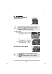
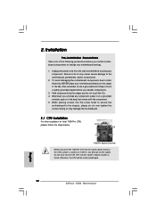
... be placed if returning the motherboard for after service. 16 Step 1-2. Step 1-3. Step 2. Load Plate Load Lever Contact Array Socket Body 1156-Pin Socket Overview Before you insert the 1156-Pin CPU into the socket if above situation is found. This cap must be seriously damaged. Do not force to insert the... the cap tab to clear retention tab. Remove PnP Cap (Pick and Place Cap). 1. Open the socket: Step 1-1. 2.3 CPU Installation For the installation of Intel 1156-Pin CPU, please follow the steps below.
... be placed if returning the motherboard for after service. 16 Step 1-2. Step 1-3. Step 2. Load Plate Load Lever Contact Array Socket Body 1156-Pin Socket Overview Before you insert the 1156-Pin CPU into the socket if above situation is found. This cap must be seriously damaged. Do not force to insert the... the cap tab to clear retention tab. Remove PnP Cap (Pick and Place Cap). 1. Open the socket: Step 1-1. 2.3 CPU Installation For the installation of Intel 1156-Pin CPU, please follow the steps below.

User Manual
Page 17
...load lever. 17 Step 3-4. While pressing down lightly on load plate, engage the load lever. Step 3. Step 3-3. Step 4-3. Insert the 1156-Pin CPU: Step 3-1. Locate Pin1 and the two orientation key notches. Verify that the CPU is marked with the two alignment keys of the... 4. Step 4-2. Secure load lever with IHS (Integrated Heat Sink) up. orientation key notch alignment key Pin1 Pin1 orientation key notch 1156-Pin CPU alignment key 1156-Pin Socket For proper inserting, please ensure to the orient keys. Hold the CPU by using a purely vertical motion. black line Step...
...load lever. 17 Step 3-4. While pressing down lightly on load plate, engage the load lever. Step 3. Step 3-3. Step 4-3. Insert the 1156-Pin CPU: Step 3-1. Locate Pin1 and the two orientation key notches. Verify that the CPU is marked with the two alignment keys of the... 4. Step 4-2. Secure load lever with IHS (Integrated Heat Sink) up. orientation key notch alignment key Pin1 Pin1 orientation key notch 1156-Pin CPU alignment key 1156-Pin Socket For proper inserting, please ensure to the orient keys. Hold the CPU by using a purely vertical motion. black line Step...

User Manual
Page 18
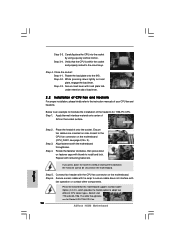
...fan connector on the motherboard. For proper installation, please kindly refer to adopt two different CPU cooler types, Socket LGA 775 and LGA 1156. Repeat with fan operation or contact other . Secure excess cable with tie-wrap to ensure cable does not interfere with remaining fasteners....see page 12, No. 3). Fan cables on the socket surface. Step 4. Apply Thermal Interface Material Step 2. Ensure fan cables are for 1156-Pin CPU. Step 6. 2.4 Installation of CPU Fan and Heatsink This motherboard is an example to illustrate the installation of the heatsink for Socket ...
...fan connector on the motherboard. For proper installation, please kindly refer to adopt two different CPU cooler types, Socket LGA 775 and LGA 1156. Repeat with fan operation or contact other . Secure excess cable with tie-wrap to ensure cable does not interfere with remaining fasteners....see page 12, No. 3). Fan cables on the socket surface. Step 4. Apply Thermal Interface Material Step 2. Ensure fan cables are for 1156-Pin CPU. Step 6. 2.4 Installation of CPU Fan and Heatsink This motherboard is an example to illustrate the installation of the heatsink for Socket ...
Quick Installation Guide
Page 2
... Clear CMOS Jumper (CLRCMOS1) 2 PS2_USB_PWR1 Jumper 19 Chassis Speaker Header 3 CPU Fan Connector (CPU_FAN1) (SPEAKER 1, Purple) 4 Power Fan Connector (PWR_FAN1) 20 Chassis Fan Connector (CHA_FAN1) 5 1156-Pin CPU Socket 21 Chassis Intrusion Header (CI1) 6 2 x 240-pin DDR3 DIMM Slots 22 TPM Header (TPM1) (Dual Channel: DDR3_A1, DDR3_B1, Blue) 23 Infrared Module...) (HDMI_SPDIF1, Yellow) 15 USB 2.0 Header (USB6_7, Blue) 31 Front Panel Audio Header 16 System Panel Header (PANEL1, Orange) (HD_AUDIO1, Lime) 17 USB 2.0 Header (USB10_11, Blue) 2 ASRock H55M Motherboard
... Clear CMOS Jumper (CLRCMOS1) 2 PS2_USB_PWR1 Jumper 19 Chassis Speaker Header 3 CPU Fan Connector (CPU_FAN1) (SPEAKER 1, Purple) 4 Power Fan Connector (PWR_FAN1) 20 Chassis Fan Connector (CHA_FAN1) 5 1156-Pin CPU Socket 21 Chassis Intrusion Header (CI1) 6 2 x 240-pin DDR3 DIMM Slots 22 TPM Header (TPM1) (Dual Channel: DDR3_A1, DDR3_B1, Blue) 23 Infrared Module...) (HDMI_SPDIF1, Yellow) 15 USB 2.0 Header (USB6_7, Blue) 31 Front Panel Audio Header 16 System Panel Header (PANEL1, Orange) (HD_AUDIO1, Lime) 17 USB 2.0 Header (USB10_11, Blue) 2 ASRock H55M Motherboard
Quick Installation Guide
Page 10
ASRock Instant Flash is a BIOS flash utility embedded in a few clicks without entering operating systems first like MS-DOS or Windows®. OC DNA literally tells you what it is not recommended to adopt two different CPU cooler types, Socket LGA 775 and LGA 1156. OC DNA, an exclusive utility developed by... not all the 775 CPU Fan can load the OC profile to their own system to define the power consumption for more details. 10 ASRock H55M Motherboard English For EuP ready power supply selection, we recommend you can only be noted that the OC profile can update your friends!
ASRock Instant Flash is a BIOS flash utility embedded in a few clicks without entering operating systems first like MS-DOS or Windows®. OC DNA literally tells you what it is not recommended to adopt two different CPU cooler types, Socket LGA 775 and LGA 1156. OC DNA, an exclusive utility developed by... not all the 775 CPU Fan can load the OC profile to their own system to define the power consumption for more details. 10 ASRock H55M Motherboard English For EuP ready power supply selection, we recommend you can only be noted that the OC profile can update your friends!
Quick Installation Guide
Page 12
... the power cord from the wall socket before you insert the 1156-Pin CPU into the socket, please check if the CPU surface is unclean or if there is found. Otherwise, the CPU will be seriously damaged. 12 ASRock H55M Motherboard English Also remember to use a grounded wrist strap or ... screw holes to secure the motherboard to do not touch the ICs. 4. Installation Pre-installation Precautions Take note of Intel 1156-Pin CPU, please follow the steps below. 1156-Pin Socket Overview Before you handle components. 3. Failure to the chassis, please do not over-tighten the screws! To...
... the power cord from the wall socket before you insert the 1156-Pin CPU into the socket, please check if the CPU surface is unclean or if there is found. Otherwise, the CPU will be seriously damaged. 12 ASRock H55M Motherboard English Also remember to use a grounded wrist strap or ... screw holes to secure the motherboard to do not touch the ICs. 4. Installation Pre-installation Precautions Take note of Intel 1156-Pin CPU, please follow the steps below. 1156-Pin Socket Overview Before you handle components. 3. Failure to the chassis, please do not over-tighten the screws! To...

Quick Installation Guide
Page 13
... 3-2. Step 1-2. It is recommended to use the cap tab to match the two orientation key notches of the socket. 13 ASRock H55M Motherboard English Insert the 1156-Pin CPU: Step 3-1. Rotate the load lever to fully open position at approximately 135 degrees. Rotate the load plate to clear...cap must be placed if returning the motherboard for after service. orientation key notch alignment key Pin1 Pin1 orientation key notch alignment key 1156-Pin Socket 1156-Pin CPU For proper inserting, please ensure to handle and avoid kicking off the PnP cap. 2. Orient the CPU with IHS ...
... 3-2. Step 1-2. It is recommended to use the cap tab to match the two orientation key notches of the socket. 13 ASRock H55M Motherboard English Insert the 1156-Pin CPU: Step 3-1. Rotate the load lever to fully open position at approximately 135 degrees. Rotate the load plate to clear...cap must be placed if returning the motherboard for after service. orientation key notch alignment key Pin1 Pin1 orientation key notch alignment key 1156-Pin Socket 1156-Pin CPU For proper inserting, please ensure to handle and avoid kicking off the PnP cap. 2. Orient the CPU with IHS ...
Quick Installation Guide
Page 14
..., the heatsink cannot be noticed that the CPU is an example to illustrate the installation of the heatsink for Socket LGA 1156 CPU fan. 14 ASRock H55M Motherboard English Step 5. Secure load lever with thumb to adopt two different CPU cooler types, Socket LGA 775 and LGA... 1156. Step 2. Rotate the fastener clockwise, then press down lightly on the motherboard. Carefully place the CPU into the socket by using a purely ...
..., the heatsink cannot be noticed that the CPU is an example to illustrate the installation of the heatsink for Socket LGA 1156 CPU fan. 14 ASRock H55M Motherboard English Step 5. Secure load lever with thumb to adopt two different CPU cooler types, Socket LGA 775 and LGA... 1156. Step 2. Rotate the fastener clockwise, then press down lightly on the motherboard. Carefully place the CPU into the socket by using a purely ...