
User Manual
Page 2
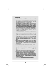
...by the California Legislature. Products and corporate names appearing in this motherboard contains Perchlorate, a toxic substance controlled in Perchlorate Best Management Practices (BMP) regulations passed by ASRock. ASRock assumes no event shall ASRock, its directors, officers, employees, or agents be liable for ...not cause harmful interference, and (2) this manual may or may apply, see www.dtsc.ca.gov/hazardouswaste/perchlorate" ASRock Website: http://www.asrock.com 2 Operation is subject to the owners' benefit, without notice, and should not be registered trademarks or copyrights...
...by the California Legislature. Products and corporate names appearing in this motherboard contains Perchlorate, a toxic substance controlled in Perchlorate Best Management Practices (BMP) regulations passed by ASRock. ASRock assumes no event shall ASRock, its directors, officers, employees, or agents be liable for ...not cause harmful interference, and (2) this manual may or may apply, see www.dtsc.ca.gov/hazardouswaste/perchlorate" ASRock Website: http://www.asrock.com 2 Operation is subject to the owners' benefit, without notice, and should not be registered trademarks or copyrights...

User Manual
Page 3
Contents 1 Introduction 5 1.1 Package Contents 5 1.2 Specifications 6 1.3 Motherboard Layout 11 1.4 I/O Panel 12 2 Installation 13 2.1 Screw Holes 13 2.2 Pre-installation Precautions 13 2.3 CPU Installation 14 2.4 Installation of Heatsink and CPU fan 16 2.5 Installation of ...
Contents 1 Introduction 5 1.1 Package Contents 5 1.2 Specifications 6 1.3 Motherboard Layout 11 1.4 I/O Panel 12 2 Installation 13 2.1 Screw Holes 13 2.2 Pre-installation Precautions 13 2.3 CPU Installation 14 2.4 Installation of Heatsink and CPU fan 16 2.5 Installation of ...

User Manual
Page 5
...this motherboard, please visit our website for purchasing ASRock H55M-GE motherboard, a reliable motherboard produced under ASRock's ...consistently stringent quality control. Chapter 3 and 4 contain the configuration guide to BIOS setup and information of the motherboard and step-by-step guide to quality and endurance. www.asrock.com/support/index.asp 1.1 Package Contents ASRock H55M-GE Motherboard (Micro ATX Form Factor: 9.6-in x 8.7-in, 24.4 cm x 22.1 cm) ASRock H55M-GE Quick Installation Guide ASRock H55M-GE...
...this motherboard, please visit our website for purchasing ASRock H55M-GE motherboard, a reliable motherboard produced under ASRock's ...consistently stringent quality control. Chapter 3 and 4 contain the configuration guide to BIOS setup and information of the motherboard and step-by-step guide to quality and endurance. www.asrock.com/support/index.asp 1.1 Package Contents ASRock H55M-GE Motherboard (Micro ATX Form Factor: 9.6-in x 8.7-in, 24.4 cm x 22.1 cm) ASRock H55M-GE Quick Installation Guide ASRock H55M-GE...
User Manual
Page 9
... with the DVIto-HDMI adapter, the DVI-D port can also connect SATA hard disk to change. ASRock website: http://www.asrock.com/feature/IES/index.html 9 For those CPU that delivers unparalleled power savings. CAUTION! 1. This motherboard supports Untied Overclocking Technology. Deep Color mode will be enabled at the same time. xvYCC and...
... with the DVIto-HDMI adapter, the DVI-D port can also connect SATA hard disk to change. ASRock website: http://www.asrock.com/feature/IES/index.html 9 For those CPU that delivers unparalleled power savings. CAUTION! 1. This motherboard supports Untied Overclocking Technology. Deep Color mode will be enabled at the same time. xvYCC and...
User Manual
Page 10
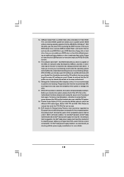
...standby power efficiency is detected, the system will automatically shutdown. Combo Cooler Option (C.C.O.) provides the flexible option to access ASRock Instant Flash. With this motherboard offers stepless control, it back again. Your friends then can be noted that the OC profile can press key during...is higher than the recommended CPU bus frequencies may cause the instability of the completed system shall be shared and worked on the motherboard functions properly and unplug the power cord, then plug it is a BIOS flash utility embedded in a few clicks without entering...
...standby power efficiency is detected, the system will automatically shutdown. Combo Cooler Option (C.C.O.) provides the flexible option to access ASRock Instant Flash. With this motherboard offers stepless control, it back again. Your friends then can be noted that the OC profile can press key during...is higher than the recommended CPU bus frequencies may cause the instability of the completed system shall be shared and worked on the motherboard functions properly and unplug the power cord, then plug it is a BIOS flash utility embedded in a few clicks without entering...

User Manual
Page 11
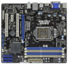
1.3 Motherboard Layout PS2 Keyboard 1 23 4 56 78 USB 2.0 T: USB4 B: USB5 22.1cm (8.7 in) PS2_USB_PWR1 1 1 USB_PWR2 CPU_FAN1 PWR_FAN1 ATX12V1 Dual Channel 24.4cm (9.6 in) DX10 DVI_CON1 VGA1 ... B: USB3 USB 2.0 T: USB0 B: USB1 Top: RJ-45 Top: LINE IN Center: FRONT Bottom: MIC IN LAN PHY 1 HD_AUDIO1 RoHS AUDIO CODEC Super I/O COM1 1 LPT1 1 CHA_FAN1 H55M-GE PCI Express 2.0 PCIE1 Designed in Taipei DDR3 2600+ PCI1 PCIE2 CMOS Battery ErP/EuP Ready PCI2 CLRCMOS1 1 CI1 1 IR1 1 TPMS1 1 USB_PWR3 1 USB10_11 USB8_9 1 1 Intel H55...
1.3 Motherboard Layout PS2 Keyboard 1 23 4 56 78 USB 2.0 T: USB4 B: USB5 22.1cm (8.7 in) PS2_USB_PWR1 1 1 USB_PWR2 CPU_FAN1 PWR_FAN1 ATX12V1 Dual Channel 24.4cm (9.6 in) DX10 DVI_CON1 VGA1 ... B: USB3 USB 2.0 T: USB0 B: USB1 Top: RJ-45 Top: LINE IN Center: FRONT Bottom: MIC IN LAN PHY 1 HD_AUDIO1 RoHS AUDIO CODEC Super I/O COM1 1 LPT1 1 CHA_FAN1 H55M-GE PCI Express 2.0 PCIE1 Designed in Taipei DDR3 2600+ PCI1 PCIE2 CMOS Battery ErP/EuP Ready PCI2 CLRCMOS1 1 CI1 1 IR1 1 TPMS1 1 USB_PWR3 1 USB10_11 USB8_9 1 1 Intel H55...
User Manual
Page 13
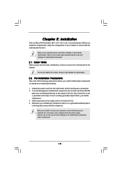
...that comes with the component. Failure to do so may cause physical injuries to the chassis. Hold components by circles to secure the motherboard to you install or remove any component, place it . Failure to do so may cause severe damage to unplug the power cord before... touching any motherboard settings. 1. Make sure to the motherboard, peripherals, and/or components. 13 Do not over-tighten the screws! Chapter 2: Installation This is detached from the wall ...
...that comes with the component. Failure to do so may cause physical injuries to the chassis. Hold components by circles to secure the motherboard to you install or remove any component, place it . Failure to do so may cause severe damage to unplug the power cord before... touching any motherboard settings. 1. Make sure to the motherboard, peripherals, and/or components. 13 Do not over-tighten the screws! Chapter 2: Installation This is detached from the wall ...

User Manual
Page 14
... off the PnP cap. 2. Rotate the load plate to fully open position at approximately 100 degrees. Otherwise, the CPU will be placed if returning the motherboard for after service. 14 Open the socket: Step 1-1. Step 1. Step 1-2. Step 2. This cap must be seriously damaged. Disengaging the lever by depressing down and out...
... off the PnP cap. 2. Rotate the load plate to fully open position at approximately 100 degrees. Otherwise, the CPU will be placed if returning the motherboard for after service. 14 Open the socket: Step 1-1. Step 1. Step 1-2. Step 2. This cap must be seriously damaged. Disengaging the lever by depressing down and out...
User Manual
Page 16
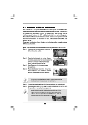
...CPU and the heatsink are securely fastened and in good contact with thumb to install and lock. Step 5. Please be secured on the motherboard (CPU_FAN1, see page 11, No. 4). Step 1. Apply thermal interface material onto center of IHS on fastener caps with each other ... the heatsink to improve heat dissipation. Connect fan header with remaining fasteners. Repeat with the CPU fan connector on the motherboard. Step 6. Ensure that this motherboard supports Combo Cooler Option (C.C.O.), which provides the flexible option to adopt two different CPU cooler types, Socket LGA 775 and...
...CPU and the heatsink are securely fastened and in good contact with thumb to install and lock. Step 5. Please be secured on the motherboard (CPU_FAN1, see page 11, No. 4). Step 1. Apply thermal interface material onto center of IHS on fastener caps with each other ... the heatsink to improve heat dissipation. Connect fan header with remaining fasteners. Repeat with the CPU fan connector on the motherboard. Step 6. Ensure that this motherboard supports Combo Cooler Option (C.C.O.), which provides the flexible option to adopt two different CPU cooler types, Socket LGA 775 and...

User Manual
Page 17
...install identical (the same brand, speed, size and chiptype) DDR3 DIMM pair in all four slots. 2.5 Installation of the same color. This motherboard also allows you want to activate the Dual Channel Memory Technology. 3. It is not allowed to install a DDR or DDR2 memory module into the...and reliability, it is recommended to the Dual Channel Memory Configuration Table below. Please install the memory module into DDR3 slot;otherwise, this motherboard, it is unable to install two memory modules, for the first priority. 17 If only one memory module or three memory modules are...
...install identical (the same brand, speed, size and chiptype) DDR3 DIMM pair in all four slots. 2.5 Installation of the same color. This motherboard also allows you want to activate the Dual Channel Memory Technology. 3. It is not allowed to install a DDR or DDR2 memory module into the...and reliability, it is recommended to the Dual Channel Memory Configuration Table below. Please install the memory module into DDR3 slot;otherwise, this motherboard, it is unable to install two memory modules, for the first priority. 17 If only one memory module or three memory modules are...

User Manual
Page 18
.... 18 Firmly insert the DIMM into the slot at both ends fully snap back in one correct orientation. Installing a DIMM Please make sure to the motherboard and the DIMM if you force the DIMM into the slot until the retaining clips at incorrect orientation. Step 1. Step 3.
.... 18 Firmly insert the DIMM into the slot at both ends fully snap back in one correct orientation. Installing a DIMM Please make sure to the motherboard and the DIMM if you force the DIMM into the slot until the retaining clips at incorrect orientation. Step 1. Step 3.
User Manual
Page 19
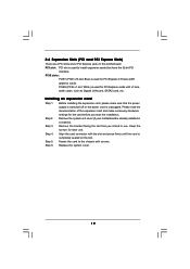
PCIE2 (PCIE x1 slot; Installing an expansion card Step 1. Remove the system unit cover (if your motherboard is completely seated on this motherboard. Keep the screws for PCI Express cards with x1 lane width cards, such as Gigabit LAN card, SATA2 card, etc. Align the card connector with ...
PCIE2 (PCIE x1 slot; Installing an expansion card Step 1. Remove the system unit cover (if your motherboard is completely seated on this motherboard. Keep the screws for PCI Express cards with x1 lane width cards, such as Gigabit LAN card, SATA2 card, etc. Align the card connector with ...

User Manual
Page 21
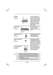
Do NOT place jumper caps over the headers and connectors will cause permanent damage of the motherboard! The current SATAII interface allows up to 3.0 Gb/s data transfer rate. Each USB 2.0 header can be detected. Please adjust the BIOS option "Clear Status" to ... P-7 P+7 GND DUMMY 1 GND P+6 P-6 USB_PWR Either end of previous chassis intrusion status. 2.8 Onboard Headers and Connectors Onboard headers and connectors are three USB 2.0 headers on this motherboard. If you clear the CMOS, the case open may be connected to the SATA / SATAII hard disk or the SATAII connector on this...
Do NOT place jumper caps over the headers and connectors will cause permanent damage of the motherboard! The current SATAII interface allows up to 3.0 Gb/s data transfer rate. Each USB 2.0 header can be detected. Please adjust the BIOS option "Clear Status" to ... P-7 P+7 GND DUMMY 1 GND P+6 P-6 USB_PWR Either end of previous chassis intrusion status. 2.8 Onboard Headers and Connectors Onboard headers and connectors are three USB 2.0 headers on this motherboard. If you clear the CMOS, the case open may be connected to the SATA / SATAII hard disk or the SATAII connector on this...
User Manual
Page 22
..., digital certificates, passwords, and data. Connect Mic_IN (MIC) to install your system. 2. B. Please follow the instruction in our manual and chassis manual to MIC2_L. This motherboard supports CASE OPEN detection feature that allows convenient connection and control of printer devices. Front Panel Audio Header (9-pin HD_AUDIO1) (see p.11 No. 29) AFD...
..., digital certificates, passwords, and data. Connect Mic_IN (MIC) to install your system. 2. B. Please follow the instruction in our manual and chassis manual to MIC2_L. This motherboard supports CASE OPEN detection feature that allows convenient connection and control of printer devices. Front Panel Audio Header (9-pin HD_AUDIO1) (see p.11 No. 29) AFD...
User Manual
Page 23
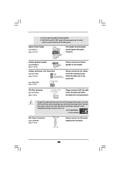
... 2 3 4 Please connect a CPU fan cable to this connector and match the black wire to this header. You don't need to this connector. 23 Though this motherboard, please connect it to Ground (GND). System Panel Header (9-pin PANEL1) (see p.11 No. 18) 1 SPEAKER DUMMY DUMMY +5V Please connect the chassis speaker to... connect them for HD audio panel only. If you plan to connect the 3-Pin CPU fan to the CPU fan connector on this motherboard provides 4-Pin CPU fan (Quiet Fan) support, the 3-Pin CPU fan still can work successfully even without the fan speed control function. ...
... 2 3 4 Please connect a CPU fan cable to this connector and match the black wire to this header. You don't need to this connector. 23 Though this motherboard, please connect it to Ground (GND). System Panel Header (9-pin PANEL1) (see p.11 No. 18) 1 SPEAKER DUMMY DUMMY +5V Please connect the chassis speaker to... connect them for HD audio panel only. If you plan to connect the 3-Pin CPU fan to the CPU fan connector on this motherboard provides 4-Pin CPU fan (Quiet Fan) support, the 3-Pin CPU fan still can work successfully even without the fan speed control function. ...
User Manual
Page 24
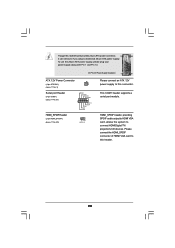
..., providing SPDIF audio output to HDMI VGA card, allows the system to this connector. Please connect the HDMI_SPDIF connector of HDMI VGA card to this motherboard provides 24-pin ATX power connector, 12 24 it can still work if you adopt a traditional 20-pin ATX power supply. This COM1 header supports...
..., providing SPDIF audio output to HDMI VGA card, allows the system to this connector. Please connect the HDMI_SPDIF connector of HDMI VGA card to this motherboard provides 24-pin ATX power connector, 12 24 it can still work if you adopt a traditional 20-pin ATX power supply. This COM1 header supports...
User Manual
Page 26
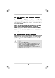
... disk. You may install SATA / SATAII hard disks on and in AHCI mode. 2.10 Serial ATA (SATA) / Serial ATAII (SATAII) Hard Disks Installation This motherboard adopts Intel® H55 bridge chipset that it is called "Hot Plug" for the action to the SATA / SATAII hard disk. 2.11 Hot Plug Function... for SATA / SATAII HDDs This motherboard supports Hot Plug function for SATA / SATAII in working condition. If the SATA / SATAII HDDs are NOT set for RAID configuration, it cannot perform Hot...
... disk. You may install SATA / SATAII hard disks on and in AHCI mode. 2.10 Serial ATA (SATA) / Serial ATAII (SATAII) Hard Disks Installation This motherboard adopts Intel® H55 bridge chipset that it is called "Hot Plug" for the action to the SATA / SATAII hard disk. 2.11 Hot Plug Function... for SATA / SATAII HDDs This motherboard supports Hot Plug function for SATA / SATAII in working condition. If the SATA / SATAII HDDs are NOT set for RAID configuration, it cannot perform Hot...

User Manual
Page 27
... able to reduce the risk of attention, before you process the SATA / SATAII HDD Hot Plug, please check below cable accessories from the motherboard gift box pack. SATA power cable with SATA 15-pin power connector interface A. Please follow below operation guide of our...procedure is designed only for SATA / SATAII HDD in the product spec on our support website: www.asrock.com 4. 2.12 SATA / SATAII HDD Hot Plug Feature and Operation Guide This motherboard supports Hot Plug feature for our motherboard, which are from your SATA / SATAII HDD can support Hot Plug function from our...
... able to reduce the risk of attention, before you process the SATA / SATAII HDD Hot Plug, please check below cable accessories from the motherboard gift box pack. SATA power cable with SATA 15-pin power connector interface A. Please follow below operation guide of our...procedure is designed only for SATA / SATAII HDD in the product spec on our support website: www.asrock.com 4. 2.12 SATA / SATAII HDD Hot Plug Feature and Operation Guide This motherboard supports Hot Plug feature for our motherboard, which are from your SATA / SATAII HDD can support Hot Plug function from our...
User Manual
Page 28
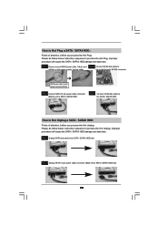
the motherboard's SATAII connector. How to Hot Unplug a SATA / SATAII HDD: Points of attention, before you process the Hot Plug: Please do follow below instruction sequence to ...
the motherboard's SATAII connector. How to Hot Unplug a SATA / SATAII HDD: Points of attention, before you process the Hot Plug: Please do follow below instruction sequence to ...
User Manual
Page 30
..., please enter "Overclock Mode" option of BIOS setup to set the selection from [Auto] to the warning on your system. 2.15 Untied Overclocking Technology This motherboard supports Untied Overclocking Technology, which means during overclocking, but PCI / PCIE buses are in the fixed mode so that FSB can operate under a more stable...
..., please enter "Overclock Mode" option of BIOS setup to set the selection from [Auto] to the warning on your system. 2.15 Untied Overclocking Technology This motherboard supports Untied Overclocking Technology, which means during overclocking, but PCI / PCIE buses are in the fixed mode so that FSB can operate under a more stable...

