
User Manual
Page 6
... Specifications 2 1.3 Motherboard Layout 7 1.4 I/O Panel 9 1.5 WiFi-802.11ac Module and ASRock WiFi 2.4/5 GHz Antennas 10 Chapter 2 Installation 12 2.1 Installing the CPU 13 2.2 Installing the CPU Fan and Heatsink 16 2.3 Installing Memory Modules (DIMM) 17 2.4 Expansion Slots (PCI Express Slot) 19 2.5 Jumpers Setup 20 2.6 Onboard Headers and Connectors 21 2.7 M.2_SSD (NGFF) Module Installation Guide 26 Chapter 3 Software and Utilities Operation 30 3.1 Installing Drivers 30 3.2 ASRock Motherboard Utility (A-Tuning) 31 3.2.1 Installing ASRock Motherboard Utility...
... Specifications 2 1.3 Motherboard Layout 7 1.4 I/O Panel 9 1.5 WiFi-802.11ac Module and ASRock WiFi 2.4/5 GHz Antennas 10 Chapter 2 Installation 12 2.1 Installing the CPU 13 2.2 Installing the CPU Fan and Heatsink 16 2.3 Installing Memory Modules (DIMM) 17 2.4 Expansion Slots (PCI Express Slot) 19 2.5 Jumpers Setup 20 2.6 Onboard Headers and Connectors 21 2.7 M.2_SSD (NGFF) Module Installation Guide 26 Chapter 3 Software and Utilities Operation 30 3.1 Installing Drivers 30 3.2 ASRock Motherboard Utility (A-Tuning) 31 3.2.1 Installing ASRock Motherboard Utility...
User Manual
Page 8
... Installation Guide • ASRock H510M-ITX/ac Support CD • 2 x Serial ATA (SATA) Data Cables (Optional) • 1 x I/O Panel Shield • 2 x ASRock WiFi 2.4/5 GHz Antennas (Optional) • 1 x Screw for specific information about the model you are using. Chapter 4 contains the configuration guide of the software and utilities. You may find the latest VGA cards and CPU support list on ASRock's website without notice. If you for purchasing ASRock H510M-ITX/ac motherboard, a reliable motherboard produced under ASRock's consistently stringent quality control. In case...
... Installation Guide • ASRock H510M-ITX/ac Support CD • 2 x Serial ATA (SATA) Data Cables (Optional) • 1 x I/O Panel Shield • 2 x ASRock WiFi 2.4/5 GHz Antennas (Optional) • 1 x Screw for specific information about the model you are using. Chapter 4 contains the configuration guide of the software and utilities. You may find the latest VGA cards and CPU support list on ASRock's website without notice. If you for purchasing ASRock H510M-ITX/ac motherboard, a reliable motherboard produced under ASRock's consistently stringent quality control. In case...

User Manual
Page 10
... Disc • Dual graphics output: support HDMI and DisplayPort 1.4 ports by independent display controllers • Supports HDMI 2.0 with max. resolution up to 4K x 2K (4096x2304) @ 60Hz • Supports Auto Lip Sync, Deep Color (12bpc), xvYCC and HBR (High Bit Rate Audio) with HDMI 2.0 Port (Compliant HDMI monitor is required) • Supports HDCP 2.3 with HDMI 2.0 and DisplayPort 1.4 Ports • Supports 4K Ultra HD (UHD) playback with HDMI 2.0 and DisplayPort 1.4 Ports * 11th Gen Intel® CoreTM Processors support HDMI 2.0. 10th...
... Disc • Dual graphics output: support HDMI and DisplayPort 1.4 ports by independent display controllers • Supports HDMI 2.0 with max. resolution up to 4K x 2K (4096x2304) @ 60Hz • Supports Auto Lip Sync, Deep Color (12bpc), xvYCC and HBR (High Bit Rate Audio) with HDMI 2.0 Port (Compliant HDMI monitor is required) • Supports HDCP 2.3 with HDMI 2.0 and DisplayPort 1.4 Ports • Supports 4K Ultra HD (UHD) playback with HDMI 2.0 and DisplayPort 1.4 Ports * 11th Gen Intel® CoreTM Processors support HDMI 2.0. 10th...

User Manual
Page 11
...-45 LAN Port with LED (ACT/LINK LED and SPEED LED) • HD Audio Jacks: Line in / Front Speaker / Microphone Storage • 4 x SATA3 6.0 Gb/s Connectors, support Intel Rapid Storage Technology 18, NCQ, AHCI and Hot Plug* * If M2_1 is occupied by a SATA-type M.2 device, SATA3_0 will be disabled. • 1 x Ultra M.2 Socket (M2_1), supports M Key type 2280 M.2 SATA3 6.0 Gb/s module and M.2 PCI Express module up to Gen3 x4 (32 Gb/s)** ** Supports NVMe SSD as boot disks ** Supports ASRock U.2 Kit Connector • 1 x Chassis Intrusion Header...
...-45 LAN Port with LED (ACT/LINK LED and SPEED LED) • HD Audio Jacks: Line in / Front Speaker / Microphone Storage • 4 x SATA3 6.0 Gb/s Connectors, support Intel Rapid Storage Technology 18, NCQ, AHCI and Hot Plug* * If M2_1 is occupied by a SATA-type M.2 device, SATA3_0 will be disabled. • 1 x Ultra M.2 Socket (M2_1), supports M Key type 2280 M.2 SATA3 6.0 Gb/s module and M.2 PCI Express module up to Gen3 x4 (32 Gb/s)** ** Supports NVMe SSD as boot disks ** Supports ASRock U.2 Kit Connector • 1 x Chassis Intrusion Header...
User Manual
Page 12
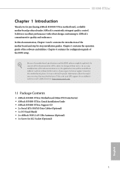
...Panel Audio Connector • 1 x USB 2.0 Header (Supports 2 USB 2.0 ports) (Supports ESD Protection) • 1 x USB 3.2 Gen1 Header (Supports 2 USB 3.2 Gen1 ports) (Supports ESD Protection) BIOS Feature • AMI UEFI Legal BIOS with multilingual GUI support • ACPI 6.0 Compliant wake up events • SMBIOS 2.7 Support • CPU, CPU GT, VCCSA, DRAM, VPPM, VCCIN AUX, VC- CIO, VCCST Voltage Multi-adjustment Hardware Monitor • Fan Tachometer: CPU, Chassis, Chassis/Water Pump Fans • Quiet Fan (Auto adjust chassis fan speed by CPU tempera- H510M-ITX/ac * The Chassis...
...Panel Audio Connector • 1 x USB 2.0 Header (Supports 2 USB 2.0 ports) (Supports ESD Protection) • 1 x USB 3.2 Gen1 Header (Supports 2 USB 3.2 Gen1 ports) (Supports ESD Protection) BIOS Feature • AMI UEFI Legal BIOS with multilingual GUI support • ACPI 6.0 Compliant wake up events • SMBIOS 2.7 Support • CPU, CPU GT, VCCSA, DRAM, VPPM, VCCIN AUX, VC- CIO, VCCST Voltage Multi-adjustment Hardware Monitor • Fan Tachometer: CPU, Chassis, Chassis/Water Pump Fans • Quiet Fan (Auto adjust chassis fan speed by CPU tempera- H510M-ITX/ac * The Chassis...

User Manual
Page 15
... 12V Power Connector (ATX12V1) 2 CPU Fan Connector (CPU_FAN1) 3 Chassis/Waterpump Fan Connector (CHA_FAN1/WP) 4 Addressable LED Header (ADDR_LED1) 5 2 x 288-pin DDR4 DIMM Slots (DDR4_A1, DDR4_B1) 6 ATX Power Connector (ATXPWR1) 7 USB 3.2 Gen1 Header (USB3_3_4) 8 SATA3 Connector (SATA3_1) 9 SATA3 Connector (SATA3_0) 10 SATA3 Connector (SATA3_3) 11 SATA3 Connector (SATA3_2) 12 System Panel Header (PANEL1) 13 USB 2.0 Header (USB_3_4) 14 Clear CMOS Jumper (CLRMOS1) 15 Chassis Speaker Header (SPEAKER1) 16 Chassis Fan Connector (CHA_FAN2) 17 Chassis Intrusion Header (CI1) 18 Front Panel Audio Header...
... 12V Power Connector (ATX12V1) 2 CPU Fan Connector (CPU_FAN1) 3 Chassis/Waterpump Fan Connector (CHA_FAN1/WP) 4 Addressable LED Header (ADDR_LED1) 5 2 x 288-pin DDR4 DIMM Slots (DDR4_A1, DDR4_B1) 6 ATX Power Connector (ATXPWR1) 7 USB 3.2 Gen1 Header (USB3_3_4) 8 SATA3 Connector (SATA3_1) 9 SATA3 Connector (SATA3_0) 10 SATA3 Connector (SATA3_3) 11 SATA3 Connector (SATA3_2) 12 System Panel Header (PANEL1) 13 USB 2.0 Header (USB_3_4) 14 Clear CMOS Jumper (CLRMOS1) 15 Chassis Speaker Header (SPEAKER1) 16 Chassis Fan Connector (CHA_FAN2) 17 Chassis Intrusion Header (CI1) 18 Front Panel Audio Header...

User Manual
Page 16
... Audio Ports in 7.1-channel Configuration: Port Light Blue (Rear panel) Lime (Rear panel) Pink (Rear panel) Lime (Front panel) Function Rear Speaker Out Front Speaker Out Central /Subwoofer Speaker Out Side Speaker Out 9 English Please refer to the table below for the LAN port LED indications. 1.4 I/O Panel 1 2 H510M-ITX/ac 3 4 10 9 No. Description 6 Antenna Ports 7 USB 2.0 Ports (USB12) 8 USB 3.2 Gen1 Ports (USB3_12) 9 DisplayPort 1.4 10 HDMI Port * There are two LEDs on each LAN port. Description 1 PS/2 Mouse/Keyboard Port 2 LAN RJ-45 Port* 3 Line In (Light...
... Audio Ports in 7.1-channel Configuration: Port Light Blue (Rear panel) Lime (Rear panel) Pink (Rear panel) Lime (Front panel) Function Rear Speaker Out Front Speaker Out Central /Subwoofer Speaker Out Side Speaker Out 9 English Please refer to the table below for the LAN port LED indications. 1.4 I/O Panel 1 2 H510M-ITX/ac 3 4 10 9 No. Description 6 Antenna Ports 7 USB 2.0 Ports (USB12) 8 USB 3.2 Gen1 Ports (USB3_12) 9 DisplayPort 1.4 10 HDMI Port * There are two LEDs on each LAN port. Description 1 PS/2 Mouse/Keyboard Port 2 LAN RJ-45 Port* 3 Line In (Light...

User Manual
Page 24
... only fits in one memory module installed. 3. H510M-ITX/ac 2.3 Installing Memory Modules (DIMM) This motherboard provides two 288-pin DDR4 (Double Data Rate 4) DIMM slots, and supports Dual Channel Memory Technology. 1. It will cause permanent damage to the motherboard and the DIMM if you always need to install identical (the same brand, speed, size and chip-type) DDR4 DIMM pairs. 2. It is not allowed to activate Dual Channel Memory Technology with only one correct...
... only fits in one memory module installed. 3. H510M-ITX/ac 2.3 Installing Memory Modules (DIMM) This motherboard provides two 288-pin DDR4 (Double Data Rate 4) DIMM slots, and supports Dual Channel Memory Technology. 1. It will cause permanent damage to the motherboard and the DIMM if you always need to install identical (the same brand, speed, size and chip-type) DDR4 DIMM pairs. 2. It is not allowed to activate Dual Channel Memory Technology with only one correct...

User Manual
Page 26
... graphics cards. 19 English H510M-ITX/ac 2.4 Expansion Slots (PCI Express Slot) There is used for PCI Express x16 lane width graphics cards. 10th Gen Intel® CoreTM Processors: PCIE1 (PCIe 3.0 x16 slot) is 1 PCI Express slot slot on the motherboard. Please read the documentation of the expansion card and make sure that the power supply is switched off or the power cord is unplugged. Before installing an expansion card, please make necessary hardware settings for the card before you start the installation...
... graphics cards. 19 English H510M-ITX/ac 2.4 Expansion Slots (PCI Express Slot) There is used for PCI Express x16 lane width graphics cards. 10th Gen Intel® CoreTM Processors: PCIE1 (PCIe 3.0 x16 slot) is 1 PCI Express slot slot on the motherboard. Please read the documentation of the expansion card and make sure that the power supply is switched off or the power cord is unplugged. Before installing an expansion card, please make necessary hardware settings for the card before you start the installation...

User Manual
Page 27
... is placed on the pins, the jumper is removed. To clear and reset the system parameters to clear the record of previous chassis intrusion status. Please adjust the BIOS option "Clear Status" to default setup, please turn off the computer and unplug the power cord from the power supply. However, please do the clear-CMOS action. If you need to short the pins on the pins, the jumper is "Open". English 20...
... is placed on the pins, the jumper is removed. To clear and reset the system parameters to clear the record of previous chassis intrusion status. Please adjust the BIOS option "Clear Status" to default setup, please turn off the computer and unplug the power cord from the power supply. However, please do the clear-CMOS action. If you need to short the pins on the pins, the jumper is "Open". English 20...
User Manual
Page 28
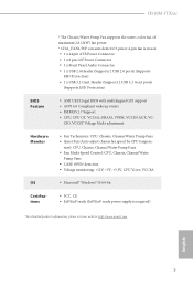
H510M-ITX/ac 2.6 Onboard Headers and Connectors Onboard headers and connectors are matched correctly. PWRBTN (Power Switch): Connect to perform a normal restart. The LED is off when the system is in S4 sleep state or powered off your chassis front panel module to this header according to this header, make sure the wire assignments and the pin assignments are NOT jumpers. A front panel module mainly consists of power switch, reset switch, power LED, hard drive activity LED, speaker and etc. English 21 Placing jumper caps over...
H510M-ITX/ac 2.6 Onboard Headers and Connectors Onboard headers and connectors are matched correctly. PWRBTN (Power Switch): Connect to perform a normal restart. The LED is off when the system is in S4 sleep state or powered off your chassis front panel module to this header according to this header, make sure the wire assignments and the pin assignments are NOT jumpers. A front panel module mainly consists of power switch, reset switch, power LED, hard drive activity LED, speaker and etc. English 21 Placing jumper caps over...

User Manual
Page 30
... connect fan cables to the fan connector and match the black wire to this header. To activate the front mic, go to OUT2_L. Chassis Fan Connector (4-pin CHA_FAN2) (see p.7, No. 15) DUMMY SPEAKER 1 +5V DUMMY Please connect the chassis speaker to the ground pin. English 23 B. Connect Mic_IN (MIC) to function correctly. E. H510M-ITX/ac 1. Chassis/Water Pump Fan Connector (4-pin CHA_FAN1/WP) (see p.7, No. 3) GND FAN_VOLTAGE CHA_FAN_SPEED FAN_SPEED_CONTROL 1 2 3 4 This motherboard provides a 4-Pin water cooling chassis fan connector. High Definition Audio supports...
... connect fan cables to the fan connector and match the black wire to this header. To activate the front mic, go to OUT2_L. Chassis Fan Connector (4-pin CHA_FAN2) (see p.7, No. 15) DUMMY SPEAKER 1 +5V DUMMY Please connect the chassis speaker to the ground pin. English 23 B. Connect Mic_IN (MIC) to function correctly. E. H510M-ITX/ac 1. Chassis/Water Pump Fan Connector (4-pin CHA_FAN1/WP) (see p.7, No. 3) GND FAN_VOLTAGE CHA_FAN_SPEED FAN_SPEED_CONTROL 1 2 3 4 This motherboard provides a 4-Pin water cooling chassis fan connector. High Definition Audio supports...

User Manual
Page 31
... This motherboard provides a 8-pin ATX 12V power connector. To use a 4-pin ATX power supply, please plug it to this header. Caution: Never install the Addressable LED cable in the wrong orientation; English If you plan to connect a 3-Pin CPU fan, please connect it along Pin 1 and Pin 5. *Warning: Please make sure that the power cable connected is used to connect Addressable LED extension cable which allows users to page 40 for the CPU and not the graphics card. Do not plug the PCIe power cable to Pin 1-3. 12...
... This motherboard provides a 8-pin ATX 12V power connector. To use a 4-pin ATX power supply, please plug it to this header. Caution: Never install the Addressable LED cable in the wrong orientation; English If you plan to connect a 3-Pin CPU fan, please connect it along Pin 1 and Pin 5. *Warning: Please make sure that the power cable connected is used to connect Addressable LED extension cable which allows users to page 40 for the CPU and not the graphics card. Do not plug the PCIe power cable to Pin 1-3. 12...
User Manual
Page 37
... 3 Software and Utilities Operation 3.1 Installing Drivers The Support CD that comes with the motherboard contains necessary drivers and useful utilities that the motherboard supports. Running The Support CD To begin using the support CD, insert the CD into your system will be auto-detected and listed on the file "ASRSETUP.EXE" in your computer. The CD automatically displays the Main Menu if "AUTORUN" is enabled in the Support CD to your CD-ROM drive.
... 3 Software and Utilities Operation 3.1 Installing Drivers The Support CD that comes with the motherboard contains necessary drivers and useful utilities that the motherboard supports. Running The Support CD To begin using the support CD, insert the CD into your system will be auto-detected and listed on the file "ASRSETUP.EXE" in your computer. The CD automatically displays the Main Menu if "AUTORUN" is enabled in the Support CD to your CD-ROM drive.
User Manual
Page 54
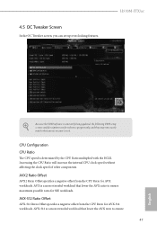
... the internal CPU clock speed without affecting the clock speed of other components. AVX-512 is a more stressful workload that lower the AVX ratio to ensure 47 English H510M-ITX/ac Because the UEFI software is determined by the CPU Ratio multiplied with the BCLK. AVX2 Ratio Offset AVX2 Ratio Offset specifies a negative offset from the CPU Ratio for AVX workloads. 4.5 OC Tweaker Screen...
... the internal CPU clock speed without affecting the clock speed of other components. AVX-512 is a more stressful workload that lower the AVX ratio to ensure 47 English H510M-ITX/ac Because the UEFI software is determined by the CPU Ratio multiplied with the BCLK. AVX2 Ratio Offset AVX2 Ratio Offset specifies a negative offset from the CPU Ratio for AVX workloads. 4.5 OC Tweaker Screen...

User Manual
Page 68
... PCIe Devices, this option Enables or Disables Single Root IO Virtualization Support. Auto mode is optimizing for PCIE1. 61 English 4.6.2 Chipset Configuration H510M-ITX/ac Primary Graphics Adapter Select a primary VGA. PCIE1 Link Speed Select the link speed for overclocking. Above 4G Decoding Enable or disable 64bit capable Devices to be decoded in Above 4G Address Space (only if the system supports 64 bit PCI decoding). VT-d Intel® Virtualization Technology for Directed I/O helps your virtual machine monitor better utilize...
... PCIe Devices, this option Enables or Disables Single Root IO Virtualization Support. Auto mode is optimizing for PCIE1. 61 English 4.6.2 Chipset Configuration H510M-ITX/ac Primary Graphics Adapter Select a primary VGA. PCIE1 Link Speed Select the link speed for overclocking. Above 4G Decoding Enable or disable 64bit capable Devices to be decoded in Above 4G Address Space (only if the system supports 64 bit PCI decoding). VT-d Intel® Virtualization Technology for Directed I/O helps your virtual machine monitor better utilize...

User Manual
Page 69
... enables/disables the ASPM support for enhanced PCI Express power saving in OS. DMI ASPM Support This option enables/disables the control of ASPM on CPU side of memory that is allocated to the integrated graphics processor when the system boots up. Select enable to disable the integrated graphics when an external graphics card is installed. Onboard HDMI HD Audio Enable audio for all CPU downstream devices. PCIE ASPM Support This option enables/disables the ASPM support for the onboard digital outputs. Onboard HD Audio Enable/disable onboard HD audio. IGPU Multi-Monitor...
... enables/disables the ASPM support for enhanced PCI Express power saving in OS. DMI ASPM Support This option enables/disables the control of ASPM on CPU side of memory that is allocated to the integrated graphics processor when the system boots up. Select enable to disable the integrated graphics when an external graphics card is installed. Onboard HDMI HD Audio Enable audio for all CPU downstream devices. PCIE ASPM Support This option enables/disables the ASPM support for the onboard digital outputs. Onboard HD Audio Enable/disable onboard HD audio. IGPU Multi-Monitor...
User Manual
Page 76
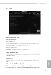
... using Internet 69 English UEFI Tech Service Contact ASRock Tech Service if you Sanitize SSD, all user data will be permanently destroyed on the SSD and cannot be recovered. NVME Sanitization Tool After you are having trouble with your UEFI. Please setup network configuration before using UEFI Tech Service. DHCP (Auto IP), Auto ASRock Internet Flash downloads and updates the latest UEFI firmware version from our servers for you. 4.7 Tools H510M-ITX/ac ASRock Polychrome RGB Select LED lighting...
... using Internet 69 English UEFI Tech Service Contact ASRock Tech Service if you Sanitize SSD, all user data will be permanently destroyed on the SSD and cannot be recovered. NVME Sanitization Tool After you are having trouble with your UEFI. Please setup network configuration before using UEFI Tech Service. DHCP (Auto IP), Auto ASRock Internet Flash downloads and updates the latest UEFI firmware version from our servers for you. 4.7 Tools H510M-ITX/ac ASRock Polychrome RGB Select LED lighting...

User Manual
Page 77
UEFI Download Server Select a server to plug in the setup utility. Flash. *For BIOS backup and recovery purpose, it is recommended to download the UEFI firmware. 70 English Internet Setting Enable or disable sound effects in your USB pen drive before using this to configure internet connection settings for Internet Flash. Network Configuration Use this function.
UEFI Download Server Select a server to plug in the setup utility. Flash. *For BIOS backup and recovery purpose, it is recommended to download the UEFI firmware. 70 English Internet Setting Enable or disable sound effects in your USB pen drive before using this to configure internet connection settings for Internet Flash. Network Configuration Use this function.
User Manual
Page 80
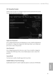
.... Supervisor Password Set or change the settings in the UEFI Setup Utility. Intel(R) Platform Trust Technology Enable/disable Intel PTT in the UEFI Setup Utility. Secure Boot Use this item to use discrete TPM Module. 73 English Disable this option to enable or disable support for the user account. Users are unable to remove the password. User Password Set or change the supervisor/user password for the administrator account. Leave it blank and press enter to change the password for the system. H510M-ITX/ac 4.9 Security Screen In...
.... Supervisor Password Set or change the settings in the UEFI Setup Utility. Intel(R) Platform Trust Technology Enable/disable Intel PTT in the UEFI Setup Utility. Secure Boot Use this item to use discrete TPM Module. 73 English Disable this option to enable or disable support for the user account. Users are unable to remove the password. User Password Set or change the supervisor/user password for the administrator account. Leave it blank and press enter to change the password for the system. H510M-ITX/ac 4.9 Security Screen In...


