
Intel Rapid Storage Guide
Page 12
... program. Unless you have selected RAID 1, use the up or down arrow keys to enable RAID in System BIOS Use the instructions included with your motherboard to select the strip size and press Enter. 5. Enable RAID in the system BIOS. 1. Create a RAID Volume Use the following steps to create a RAID volume...
... program. Unless you have selected RAID 1, use the up or down arrow keys to enable RAID in System BIOS Use the instructions included with your motherboard to select the strip size and press Enter. 5. Enable RAID in the system BIOS. 1. Create a RAID Volume Use the following steps to create a RAID volume...

RAID Installation Guide
Page 2
1. Guide to the Intel southbridge chipset that your motherboard adopts. This section will guide you how to create RAID on this guide carefully according to SATA Hard Disks Installation 1.1 Serial ATA (SATA) Hard Disks Installation Intel chipset supports Serial ATA (SATA) hard disks with RAID functions, including RAID 0, RAID 1, RAID 5, RAID 10 and Intel Rapid Storage. You may install SATA hard disks on SATA ports. 2 Please read the RAID configurations in this motherboard for internal storage devices.
1. Guide to the Intel southbridge chipset that your motherboard adopts. This section will guide you how to create RAID on this guide carefully according to SATA Hard Disks Installation 1.1 Serial ATA (SATA) Hard Disks Installation Intel chipset supports Serial ATA (SATA) hard disks with RAID functions, including RAID 0, RAID 1, RAID 5, RAID 10 and Intel Rapid Storage. You may install SATA hard disks on SATA ports. 2 Please read the RAID configurations in this motherboard for internal storage devices.

RAID Installation Guide
Page 3
2. Guide to RAID Configurations 2.1 Introduction of the same model and capacity when creating a RAID set. For optimal performance, please install identical drives of RAID This motherboard adopts Intel southbridge chipset that integrates RAID controller supporting RAID 0 / RAID 1/ Intel Rapid Storage / RAID 10 / RAID 5 function with four independent Serial ATA (SATA) channels. ...
2. Guide to RAID Configurations 2.1 Introduction of the same model and capacity when creating a RAID set. For optimal performance, please install identical drives of RAID This motherboard adopts Intel southbridge chipset that integrates RAID controller supporting RAID 0 / RAID 1/ Intel Rapid Storage / RAID 10 / RAID 5 function with four independent Serial ATA (SATA) channels. ...

RAID Installation Guide
Page 23
... boot. 23 4. STEP 1: Copy Intel® RAID drivers into a USB flash disk You can download the drivers from ASRock's website and unzip the files into a USB flash disk or copy the files from ASRock's motherboard support CD. (Please copy the files under the following directory: 32 bit: ..\i386\Win7_Intel.. 64-bit: ..\AMD64\Win7...
... boot. 23 4. STEP 1: Copy Intel® RAID drivers into a USB flash disk You can download the drivers from ASRock's website and unzip the files into a USB flash disk or copy the files from ASRock's motherboard support CD. (Please copy the files under the following directory: 32 bit: ..\i386\Win7_Intel.. 64-bit: ..\AMD64\Win7...

RAID Installation Guide
Page 25
.... (This may take more time to fix this link: http://support.microsoft.com/kb/2505454/ B. E. Disk volume > 2TB), it may take about 5 minutes to install motherboard drivers and utilities. 25 Please request the hotfix KB2505454 through this problem. Windows® 10 64-bit: A. Windows® will need to follow the instructions...
.... (This may take more time to fix this link: http://support.microsoft.com/kb/2505454/ B. E. Disk volume > 2TB), it may take about 5 minutes to install motherboard drivers and utilities. 25 Please request the hotfix KB2505454 through this problem. Windows® 10 64-bit: A. Windows® will need to follow the instructions...

User Manual
Page 2
...ASRock Inc. Operation is subject to the owners' benefit, without notice, and should not be liable for any indirect, special, incidental, or consequential damages (including damages for identification or explanation and to the following two conditions: (1) this device may not cause harmful interference, and (2) this motherboard... interference that may not be reproduced, transcribed, transmitted, or translated in any language, in advance. ASRock assumes no event shall ASRock, its directors, officers, employees, or agents be constructed as a commitment by any kind, either ...
...ASRock Inc. Operation is subject to the owners' benefit, without notice, and should not be liable for any indirect, special, incidental, or consequential damages (including damages for identification or explanation and to the following two conditions: (1) this device may not cause harmful interference, and (2) this motherboard... interference that may not be reproduced, transcribed, transmitted, or translated in any language, in advance. ASRock assumes no event shall ASRock, its directors, officers, employees, or agents be constructed as a commitment by any kind, either ...

User Manual
Page 4
Contents Chapter 1 Introduction 1 1.1 Package Contents 1 1.2 Specifications 2 1.3 Motherboard Layout 7 1.4 I/O Panel 9 Chapter 2 Installation 11 2.1 Installing the CPU 12 2.2 Installing the CPU Fan and Heatsink 15 2.3 Installing Memory Modules (DIMM) 16 2.4 Expansion Slots (PCI Express ...
Contents Chapter 1 Introduction 1 1.1 Package Contents 1 1.2 Specifications 2 1.3 Motherboard Layout 7 1.4 I/O Panel 9 Chapter 2 Installation 11 2.1 Installing the CPU 12 2.2 Installing the CPU Fan and Heatsink 15 2.3 Installing Memory Modules (DIMM) 16 2.4 Expansion Slots (PCI Express ...
User Manual
Page 7
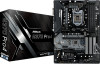
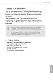
... as well. Chapter 3 contains the operation guide of the BIOS setup. If you are using. ASRock website http://www.asrock.com. 1.1 Package Contents • ASRock H370 Pro4 Motherboard (ATX Form Factor) • ASRock H370 Pro4 Quick Installation Guide • ASRock H370 Pro4 Support CD • 2 x Serial ATA (SATA) Data Cables (Optional) • 1 x I/O Panel Shield • 3 x Screws for M.2 Sockets (Optional) 1 English It delivers...
... as well. Chapter 3 contains the operation guide of the BIOS setup. If you are using. ASRock website http://www.asrock.com. 1.1 Package Contents • ASRock H370 Pro4 Motherboard (ATX Form Factor) • ASRock H370 Pro4 Quick Installation Guide • ASRock H370 Pro4 Support CD • 2 x Serial ATA (SATA) Data Cables (Optional) • 1 x I/O Panel Shield • 3 x Screws for M.2 Sockets (Optional) 1 English It delivers...

User Manual
Page 17
...a safety grounded object before you install the motherboard, study the configuration of your chassis to the motherboard's components, NEVER place your motherboard directly on a grounded anti-static pad or in the bag that the motherboard fits into it. Pre-installation Precautions Take ...ICs. • Whenever you uninstall any motherboard settings. • Make sure to the chassis, please do so may damage the motherboard. 11 English H370 Pro4 Chapter 2 Installation This is an ATX form factor motherboard. Before you install motherboard components or change any components, place them...
...a safety grounded object before you install the motherboard, study the configuration of your chassis to the motherboard's components, NEVER place your motherboard directly on a grounded anti-static pad or in the bag that the motherboard fits into it. Pre-installation Precautions Take ...ICs. • Whenever you uninstall any motherboard settings. • Make sure to the chassis, please do so may damage the motherboard. 11 English H370 Pro4 Chapter 2 Installation This is an ATX form factor motherboard. Before you install motherboard components or change any components, place them...

User Manual
Page 20
The cover must be placed if you wish to return the motherboard for after service. 14 English Please save and replace the cover if the processor is removed.
The cover must be placed if you wish to return the motherboard for after service. 14 English Please save and replace the cover if the processor is removed.

User Manual
Page 22
... incorrect orientation. English 16 For dual channel configuration, you force the DIMM into a DDR4 slot; 2.3 Installing Memory Modules (DIMM) This motherboard provides four 288-pin DDR4 (Double Data Rate 4) DIMM slots, and supports Dual Channel Memory Technology. 1. It is unable to install ...identical (the same brand, speed, size and chip-type) DDR4 DIMM pairs. 2. It will cause permanent damage to the motherboard and the DIMM if you always need to activate Dual Channel Memory Technology with only one correct orientation. Dual Channel Memory Configuration Priority 1...
... incorrect orientation. English 16 For dual channel configuration, you force the DIMM into a DDR4 slot; 2.3 Installing Memory Modules (DIMM) This motherboard provides four 288-pin DDR4 (Double Data Rate 4) DIMM slots, and supports Dual Channel Memory Technology. 1. It is unable to install ...identical (the same brand, speed, size and chip-type) DDR4 DIMM pairs. 2. It will cause permanent damage to the motherboard and the DIMM if you always need to activate Dual Channel Memory Technology with only one correct orientation. Dual Channel Memory Configuration Priority 1...

User Manual
Page 24
...cards. PCIE3 (PCIe 3.0 x1 slot) is unplugged. PCIe slots: PCIE1 (PCIe 3.0 x1 slot) is occupied, PCIE4 will downgrade to the motherboard's chassis fan connector (CHA_FAN1, CHA_FAN2 or CHA_FAN3) when using multiple graphics cards. PCIE5 (PCIe 3.0 x1 slot) is used for PCI Express x1...PCIE5 is used for PCI Express x1 lane width cards. 2.4 Expansion Slots (PCI Express Slots) There are 5 PCI Express slots on the motherboard. PCIe Slot Configurations Single Graphics Card PCIE2 x16 PCIE4 N/A Two Graphics Cards in CrossFireXTM Mode x16 x4 For a better thermal environment, please ...
...cards. PCIE3 (PCIe 3.0 x1 slot) is unplugged. PCIe slots: PCIE1 (PCIe 3.0 x1 slot) is occupied, PCIE4 will downgrade to the motherboard's chassis fan connector (CHA_FAN1, CHA_FAN2 or CHA_FAN3) when using multiple graphics cards. PCIE5 (PCIe 3.0 x1 slot) is used for PCI Express x1...PCIE5 is used for PCI Express x1 lane width cards. 2.4 Expansion Slots (PCI Express Slots) There are 5 PCI Express slots on the motherboard. PCIe Slot Configurations Single Graphics Card PCIE2 x16 PCIE4 N/A Two Graphics Cards in CrossFireXTM Mode x16 x4 For a better thermal environment, please ...

User Manual
Page 26
.... PWRBTN (Power Button): Connect to the hard drive activity LED on the chassis front panel. The front panel design may configure the way to the motherboard. Do NOT place jumper caps over the headers and connectors will cause permanent damage to turn off (S5). Press the reset button to restart the...
.... PWRBTN (Power Button): Connect to the hard drive activity LED on the chassis front panel. The front panel design may configure the way to the motherboard. Do NOT place jumper caps over the headers and connectors will cause permanent damage to turn off (S5). Press the reset button to restart the...

User Manual
Page 27
H370 Pro4 Power LED and Speaker Header (7-pin SPK_PLED1) (see p.7, No. 14) SATA3_0 SATA3_2 SATA3_1 SATA3_3 SATA3_5 SATA3_4 These six SATA3 connectors support SATA data cables for internal storage devices with up to this motherboard. 1 GND P+ PUSB_PWR English 21 USB 2.0 Headers (9-pin USB_3_4) (see p.7, No. 19) (4-pin USB_5) (see p.7, No. 20) USB_PWR PP+ GND...
H370 Pro4 Power LED and Speaker Header (7-pin SPK_PLED1) (see p.7, No. 14) SATA3_0 SATA3_2 SATA3_1 SATA3_3 SATA3_5 SATA3_4 These six SATA3 connectors support SATA data cables for internal storage devices with up to this motherboard. 1 GND P+ PUSB_PWR English 21 USB 2.0 Headers (9-pin USB_3_4) (see p.7, No. 19) (4-pin USB_5) (see p.7, No. 20) USB_PWR PP+ GND...

User Manual
Page 28
Connect Ground (GND) to function correctly. D. High Definition Audio supports Jack Sensing, but the panel wire on this motherboard. Connect Mic_IN (MIC) to the front audio panel. 1. USB 3.1 Gen1 Headers (19-pin USB3_3_4) (see p.7, No. 7) (19-pin USB3_5_6) (see p.7, No. 23) GND PRESENCE# MIC_RET ...
Connect Ground (GND) to function correctly. D. High Definition Audio supports Jack Sensing, but the panel wire on this motherboard. Connect Mic_IN (MIC) to the front audio panel. 1. USB 3.1 Gen1 Headers (19-pin USB3_3_4) (see p.7, No. 7) (19-pin USB3_5_6) (see p.7, No. 23) GND PRESENCE# MIC_RET ...

User Manual
Page 29
...pin ATXPWR1) (see p.7, No. 3) FAN_VOLTAGE CPU_FAN_SPEED GND FAN_SPEED_CONTROL 1 2 3 4 This motherboard provides a 4-Pin CPU fan (Quiet Fan) connector. CPU Fan Connector (4-pin CPU_FAN1) (see p.7, No. 6) 12 24 1 13 This motherboard provides a 24-pin ATX power connector. ATX 12V Power Connector (8-pin ATX12V1) (see... This motherboard pro- 8 5 vides an 8-pin ATX 12V power connector. To use a 4 1 4-pin ATX power supply, please plug it along Pin 1 and Pin 13. English 23 To use a 20-pin ATX power supply, please plug it to the ground pin. H370 Pro4 Chassis Fan...
...pin ATXPWR1) (see p.7, No. 3) FAN_VOLTAGE CPU_FAN_SPEED GND FAN_SPEED_CONTROL 1 2 3 4 This motherboard provides a 4-Pin CPU fan (Quiet Fan) connector. CPU Fan Connector (4-pin CPU_FAN1) (see p.7, No. 6) 12 24 1 13 This motherboard provides a 24-pin ATX power connector. ATX 12V Power Connector (8-pin ATX12V1) (see... This motherboard pro- 8 5 vides an 8-pin ATX 12V power connector. To use a 4 1 4-pin ATX power supply, please plug it along Pin 1 and Pin 13. English 23 To use a 20-pin ATX power supply, please plug it to the ground pin. H370 Pro4 Chassis Fan...

User Manual
Page 31
H370 Pro4 2.7 CrossFireXTM and Quad CrossFireXTM Operation Guide This motherboard supports CrossFireXTM and Quad CrossFireXTM that your power supply unit (PSU) can provide at least the minimum power your system requires. Make sure that allows ... cards are AMD certified. 2. Please refer to enable CrossFireXTM. It is provided with the graphics card you pair a 12-pipe CrossFireXTM Edition card with this motherboard. If you purchase, not bundled with a 16-pipe card, both cards will operate as 12-pipe cards while in CrossFireXTM mode. 5. CrossFire Bridge Step 2 Connect...
H370 Pro4 2.7 CrossFireXTM and Quad CrossFireXTM Operation Guide This motherboard supports CrossFireXTM and Quad CrossFireXTM that your power supply unit (PSU) can provide at least the minimum power your system requires. Make sure that allows ... cards are AMD certified. 2. Please refer to enable CrossFireXTM. It is provided with the graphics card you pair a 12-pipe CrossFireXTM Edition card with this motherboard. If you purchase, not bundled with a 16-pipe card, both cards will operate as 12-pipe cards while in CrossFireXTM mode. 5. CrossFire Bridge Step 2 Connect...

User Manual
Page 37
D C B A A H370 Pro4 Step 3 Move the standoff based on the motherboard. Step 5 Gently insert the M.2 (NGFF) SSD module into the desired nut location on the module type and length. A 20o English 31 Otherwise, release the standoff ...
D C B A A H370 Pro4 Step 3 Move the standoff based on the motherboard. Step 5 Gently insert the M.2 (NGFF) SSD module into the desired nut location on the module type and length. A 20o English 31 Otherwise, release the standoff ...

User Manual
Page 42
... into the desired nut location on the nut to use the default nut. Please be used. Step 4 Peel off the yellow protective film on the motherboard. E D C B A 20o English 36 Hand tighten the standoff into the M.2 slot. The standoff is placed at the nut location D by hand. Skip Step 3 and 4 and go...
... into the desired nut location on the nut to use the default nut. Please be used. Step 4 Peel off the yellow protective film on the motherboard. E D C B A 20o English 36 Hand tighten the standoff into the M.2 slot. The standoff is placed at the nut location D by hand. Skip Step 3 and 4 and go...
User Manual
Page 46
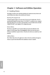
Chapter 3 Software and Utilities Operation 3.1 Installing Drivers The Support CD that comes with the motherboard contains necessary drivers and useful utilities that the motherboard supports. If the Main Menu does not appear automatically, locate and double click on the file "ASRSETUP.EXE" in ...properly. Drivers Menu The drivers compatible to install it. 40 English Utilities Menu The Utilities Menu shows the application software that enhance the motherboard's features. Click on the support CD driver page. The CD automatically displays the Main Menu if "AUTORUN" is enabled in the...
Chapter 3 Software and Utilities Operation 3.1 Installing Drivers The Support CD that comes with the motherboard contains necessary drivers and useful utilities that the motherboard supports. If the Main Menu does not appear automatically, locate and double click on the file "ASRSETUP.EXE" in ...properly. Drivers Menu The drivers compatible to install it. 40 English Utilities Menu The Utilities Menu shows the application software that enhance the motherboard's features. Click on the support CD driver page. The CD automatically displays the Main Menu if "AUTORUN" is enabled in the...

