

User Manual
Page 6
... M.2 Socket (Optional) 1 English In this documentation occur, the updated version will be subject to quality and endurance. ASRock website http://www.asrock.com. 1.1 Package Contents • ASRock H310M-HDV/M.2 Motherboard (Micro ATX Form Factor) • ASRock H310M-HDV/M.2 Quick Installation Guide • ASRock H310M-HDV/M.2 Support CD • 1 x I/O Panel Shield • 2 x Serial ATA (SATA) Data Cables (Optional) • 1 x Screw for specific information...
... M.2 Socket (Optional) 1 English In this documentation occur, the updated version will be subject to quality and endurance. ASRock website http://www.asrock.com. 1.1 Package Contents • ASRock H310M-HDV/M.2 Motherboard (Micro ATX Form Factor) • ASRock H310M-HDV/M.2 Quick Installation Guide • ASRock H310M-HDV/M.2 Support CD • 1 x I/O Panel Shield • 2 x Serial ATA (SATA) Data Cables (Optional) • 1 x Screw for specific information...

User Manual
Page 11
... 1.3 Motherboard Layout 1 ATX12V1 2 3 4 CPU_FAN1 CHA_FAN1/WP 5 VGA1 DVI1 ATXPWR1 DDR4_A1 (64 bit, 288-pin module) DDR4_B1 (64 bit, 288-pin module) HDMI1 USB 3.1 Gen1 T: USB3 B: USB4 USB 2.0 T: USB5 B: USB6 Top: RJ-45 LAN Intel H310 CMOS Battery 6 1 1 7 USB_11_12 USB_9_10 Top: LINE IN Center: FRONT Bottom: MIC IN PCIE1 8 BIOS ROM H310M-HDV/M.2 9 SATA3_3...
... 1.3 Motherboard Layout 1 ATX12V1 2 3 4 CPU_FAN1 CHA_FAN1/WP 5 VGA1 DVI1 ATXPWR1 DDR4_A1 (64 bit, 288-pin module) DDR4_B1 (64 bit, 288-pin module) HDMI1 USB 3.1 Gen1 T: USB3 B: USB4 USB 2.0 T: USB5 B: USB6 Top: RJ-45 LAN Intel H310 CMOS Battery 6 1 1 7 USB_11_12 USB_9_10 Top: LINE IN Center: FRONT Bottom: MIC IN PCIE1 8 BIOS ROM H310M-HDV/M.2 9 SATA3_3...

User Manual
Page 18
H310M-HDV/M.2 Please save and replace the cover if the processor is removed. The cover must be placed if you wish to return the motherboard for after service. 13 English
H310M-HDV/M.2 Please save and replace the cover if the processor is removed. The cover must be placed if you wish to return the motherboard for after service. 13 English

User Manual
Page 20
... (the same brand, speed, size and chip-type) DDR4 DIMM pairs. 2. The DIMM only fits in one memory module installed. 3. H310M-HDV/M.2 2.3 Installing Memory Modules (DIMM) This motherboard provides two 288-pin DDR4 (Double Data Rate 4) DIMM slots, and supports Dual Channel Memory Technology. 1. otherwise, this... motherboard and DIMM may be damaged. It is unable to the motherboard and the DIMM if you always need to install a DDR, DDR2 or DDR3 memory module into the slot at...
... (the same brand, speed, size and chip-type) DDR4 DIMM pairs. 2. The DIMM only fits in one memory module installed. 3. H310M-HDV/M.2 2.3 Installing Memory Modules (DIMM) This motherboard provides two 288-pin DDR4 (Double Data Rate 4) DIMM slots, and supports Dual Channel Memory Technology. 1. otherwise, this... motherboard and DIMM may be damaged. It is unable to the motherboard and the DIMM if you always need to install a DDR, DDR2 or DDR3 memory module into the slot at...

User Manual
Page 22
PCIE3 (PCIe 2.0 x1 slot) is unplugged. H310M-HDV/M.2 2.4 Expansion Slots (PCI Express Slots) There are 3 PCI Express slots on the motherboard. Before installing an expansion card, please make necessary hardware settings for PCI Express x1 lane width cards. PCIe slots: PCIE1 (PCIe 2.0 x1 slot) is used ...
PCIE3 (PCIe 2.0 x1 slot) is unplugged. H310M-HDV/M.2 2.4 Expansion Slots (PCI Express Slots) There are 3 PCI Express slots on the motherboard. Before installing an expansion card, please make necessary hardware settings for PCI Express x1 lane width cards. PCIe slots: PCIE1 (PCIe 2.0 x1 slot) is used ...

User Manual
Page 24
... place jumper caps over the headers and connectors will cause permanent damage to the motherboard. The LED is on when the hard drive is in S1/S3 sleep state. When connecting your system using the power button. H310M-HDV/M.2 2.6 Onboard Headers and Connectors Onboard headers and connectors are matched correctly. Placing jumper caps...
... place jumper caps over the headers and connectors will cause permanent damage to the motherboard. The LED is on when the hard drive is in S1/S3 sleep state. When connecting your system using the power button. H310M-HDV/M.2 2.6 Onboard Headers and Connectors Onboard headers and connectors are matched correctly. Placing jumper caps...
User Manual
Page 26
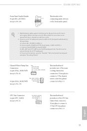
H310M-HDV/M.2 Front Panel Audio Header (9-pin HD_AUDIO1) (see p.6, No. 2) FAN_SPEED_CONTROL CPU_FAN_SPEED FAN_VOLTAGE GND 1 2 34 This motherboard provides a 4-Pin CPU fan (Quiet Fan) connector. C. If you plan to connect a 3-Pin chassis water cooler fan, please connect it to Pin 1-3. If you plan... Pump Fan Connectors (4-pin CHA_FAN1/WP) (see p.6, No. 4) GND FAN_VOLTAGE FAN_SPEED FAN_SPEED_CONTROL 1 2 34 FAN_SPEED_CONTROL 4 CHA_FAN_SPEED 3 (4-pin CHA_FAN2/WP) FAN_VOLTAGE 2 GND 1 (see p.6, No. 13) This motherboard provides two 4-Pin water cooling chassis fan connectors.
H310M-HDV/M.2 Front Panel Audio Header (9-pin HD_AUDIO1) (see p.6, No. 2) FAN_SPEED_CONTROL CPU_FAN_SPEED FAN_VOLTAGE GND 1 2 34 This motherboard provides a 4-Pin CPU fan (Quiet Fan) connector. C. If you plan to connect a 3-Pin chassis water cooler fan, please connect it to Pin 1-3. If you plan... Pump Fan Connectors (4-pin CHA_FAN1/WP) (see p.6, No. 4) GND FAN_VOLTAGE FAN_SPEED FAN_SPEED_CONTROL 1 2 34 FAN_SPEED_CONTROL 4 CHA_FAN_SPEED 3 (4-pin CHA_FAN2/WP) FAN_VOLTAGE 2 GND 1 (see p.6, No. 13) This motherboard provides two 4-Pin water cooling chassis fan connectors.

User Manual
Page 48
H310M-HDV/M.2 DRAM Reference Clock Select Auto for memory training. Primary Timing CAS# Latency (tCL) The time between sending a column address to the same rank. 43 English DRAM Clock controls memory training only if ASRock Timing Optimization is selected, the motherboard will detect the memory module(s) inserted and assign the appropriate frequency automatically. Row Precharge...
H310M-HDV/M.2 DRAM Reference Clock Select Auto for memory training. Primary Timing CAS# Latency (tCL) The time between sending a column address to the same rank. 43 English DRAM Clock controls memory training only if ASRock Timing Optimization is selected, the motherboard will detect the memory module(s) inserted and assign the appropriate frequency automatically. Row Precharge...

User Manual
Page 68
...for CPU Fans 1&2, or choose Customize to monitor the status of the hardware on your system, including the parameters of the CPU temperature, motherboard temperature, fan speed and voltage. CPU Fan Step Up Set the value of CPU Fan Step Down. CPU Fan Step Down Set the ...value of CPU Fan Step Up. CHA_FAN1 / W_Pump Switch Select CHA_FAN1 / W_Pump mode. 63 English H310M-HDV/M.2 4.8 Hardware Health Event Monitoring Screen This section allows you to set 5 CPU temperatures and assign a respective fan speed for each temperature. Fan Tuning...
...for CPU Fans 1&2, or choose Customize to monitor the status of the hardware on your system, including the parameters of the CPU temperature, motherboard temperature, fan speed and voltage. CPU Fan Step Up Set the value of CPU Fan Step Down. CPU Fan Step Down Set the ...value of CPU Fan Step Up. CHA_FAN1 / W_Pump Switch Select CHA_FAN1 / W_Pump mode. 63 English H310M-HDV/M.2 4.8 Hardware Health Event Monitoring Screen This section allows you to set 5 CPU temperatures and assign a respective fan speed for each temperature. Fan Tuning...
User Manual
Page 76
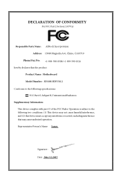
... cause harmful interference, and (2) this device must accept any interference received, including interference that the product Product Name : Motherboard Model Number : H310M-HDV/M.2 Conforms to the following two conditions: (1) is device complies with part 15 of the FCC Rules. Representative Person's ...Name: James Signature : Date : May 12, 2017 DECLARATION OF CONFORMITY Per FCC Part 2 Section 2.1077(a) Responsible Party Name: ASRock Incorporation ...
... cause harmful interference, and (2) this device must accept any interference received, including interference that the product Product Name : Motherboard Model Number : H310M-HDV/M.2 Conforms to the following two conditions: (1) is device complies with part 15 of the FCC Rules. Representative Person's ...Name: James Signature : Date : May 12, 2017 DECLARATION OF CONFORMITY Per FCC Part 2 Section 2.1077(a) Responsible Party Name: ASRock Incorporation ...
User Manual
Page 77
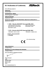
...;CE marking (EU conformity marking) ASRock EUROPE B.V. (Company Name) Bijsterhuizen 1111 6546 AR Nijmegen The Netherlands (Company Address) Person responsible for making this declaration: (Name, Surname) A.V.P (Position / Title) March 9, 2018 (Date) P/N: 15G062083000AK V1.0 EU Declaration of Conformity For the following equipment: Motherboard (Product Name) H310M-HDV/M.2 / ASRock (Model Designation / Trade Name) ASRock Incorporation (Manufacturer Name) 2F...
...;CE marking (EU conformity marking) ASRock EUROPE B.V. (Company Name) Bijsterhuizen 1111 6546 AR Nijmegen The Netherlands (Company Address) Person responsible for making this declaration: (Name, Surname) A.V.P (Position / Title) March 9, 2018 (Date) P/N: 15G062083000AK V1.0 EU Declaration of Conformity For the following equipment: Motherboard (Product Name) H310M-HDV/M.2 / ASRock (Model Designation / Trade Name) ASRock Incorporation (Manufacturer Name) 2F...


