

User Manual
Page 4
... Contents 1 1.2 Specifications 2 1.3 Motherboard Layout 6 1.4 I/O Panel 8 Chapter 2 Installation 10 2.1 Installing the CPU 11 2.2 Installing the CPU Fan and Heatsink 14 2.3 Installing Memory Modules (DIMM) 15 2.4 Expansion Slots (PCI Express Slots) 17 2.5 Jumpers Setup 18 2.6 Onboard Headers and Connectors 19 Chapter 3 Software and Utilities Operation 26 3.1 Installing Drivers 26 3.2 A-Tuning 27 3.3 ASRock Live Update & APP Shop 30 3.3.1 UI Overview 30 3.3.2 Apps 31 3.3.3 BIOS & Drivers 34 3.3.4 Setting 35 Chapter 4 UEFI SETUP UTILITY 36 4.1 Introduction...
... Contents 1 1.2 Specifications 2 1.3 Motherboard Layout 6 1.4 I/O Panel 8 Chapter 2 Installation 10 2.1 Installing the CPU 11 2.2 Installing the CPU Fan and Heatsink 14 2.3 Installing Memory Modules (DIMM) 15 2.4 Expansion Slots (PCI Express Slots) 17 2.5 Jumpers Setup 18 2.6 Onboard Headers and Connectors 19 Chapter 3 Software and Utilities Operation 26 3.1 Installing Drivers 26 3.2 A-Tuning 27 3.3 ASRock Live Update & APP Shop 30 3.3.1 UI Overview 30 3.3.2 Apps 31 3.3.3 BIOS & Drivers 34 3.3.4 Setting 35 Chapter 4 UEFI SETUP UTILITY 36 4.1 Introduction...

User Manual
Page 6
...about the model you are using. You may find the latest VGA cards and CPU support list on ASRock's website without notice. Because the motherboard specifications and the BIOS software might be updated, the content of the motherboard and step-by-step installation guides. ASRock website http://www.asrock.com. 1.1 Package Contents • ASRock H310M-HDV/M.2 Motherboard (Micro ATX Form Factor) • ASRock H310M-HDV/M.2 Quick Installation Guide • ASRock H310M-HDV/M.2 Support CD • 1 x I/O Panel Shield • 2 x Serial ATA (SATA) Data Cables (Optional) • 1 x Screw...
...about the model you are using. You may find the latest VGA cards and CPU support list on ASRock's website without notice. Because the motherboard specifications and the BIOS software might be updated, the content of the motherboard and step-by-step installation guides. ASRock website http://www.asrock.com. 1.1 Package Contents • ASRock H310M-HDV/M.2 Motherboard (Micro ATX Form Factor) • ASRock H310M-HDV/M.2 Quick Installation Guide • ASRock H310M-HDV/M.2 Support CD • 1 x I/O Panel Shield • 2 x Serial ATA (SATA) Data Cables (Optional) • 1 x Screw...

User Manual
Page 8
... (High Bit Rate Audio) with HDMI Port (Compliant HDMI monitor is required) • Supports HDCP with DVI-D and HDMI Ports • Supports 4K Ultra HD (UHD) playback with HDMI Port Audio • 7.1 CH HD Audio (Realtek ALC887 Audio Codec) * To configure 7.1 CH HD Audio, it is required to 4K x 2K (4096x2160) @ 30Hz • Supports DVI-D with max. resolution up to 2 displays simultaneously • Supports HDMI with max. H310M-HDV/M.2 • Three graphics output options: D-Sub, DVI-D and HDMI * Supports up...
... (High Bit Rate Audio) with HDMI Port (Compliant HDMI monitor is required) • Supports HDCP with DVI-D and HDMI Ports • Supports 4K Ultra HD (UHD) playback with HDMI Port Audio • 7.1 CH HD Audio (Realtek ALC887 Audio Codec) * To configure 7.1 CH HD Audio, it is required to 4K x 2K (4096x2160) @ 30Hz • Supports DVI-D with max. resolution up to 2 displays simultaneously • Supports HDMI with max. H310M-HDV/M.2 • Three graphics output options: D-Sub, DVI-D and HDMI * Supports up...

User Manual
Page 9
...Water Pump Fans 4 BIOS Feature • AMI UEFI Legal BIOS with multilingual GUI support • ACPI 6.0 Compliant wake up to Gen2 x4 (20 Gb/s)** ** Supports NVMe SSD as boot disks ** Supports ASRock U.2 Kit Connector • 1 x Print Port Header • 1 x COM Port Header • 1 x TPM Header • 1 x Chassis Intrusion and Speaker Header • 1 x CPU Fan Connector (4-pin) * The CPU Fan Connector supports the CPU fan of maximum 1A (12W) fan power. • 2 x Chassis/Water Pump Fan Connectors (4-pin) (Smart Fan Speed Control) * The Chassis/Water Pump Fan supports the water...
...Water Pump Fans 4 BIOS Feature • AMI UEFI Legal BIOS with multilingual GUI support • ACPI 6.0 Compliant wake up to Gen2 x4 (20 Gb/s)** ** Supports NVMe SSD as boot disks ** Supports ASRock U.2 Kit Connector • 1 x Print Port Header • 1 x COM Port Header • 1 x TPM Header • 1 x Chassis Intrusion and Speaker Header • 1 x CPU Fan Connector (4-pin) * The CPU Fan Connector supports the CPU fan of maximum 1A (12W) fan power. • 2 x Chassis/Water Pump Fan Connectors (4-pin) (Smart Fan Speed Control) * The Chassis/Water Pump Fan supports the water...

User Manual
Page 10
... damage caused by CPU temperature): CPU, Chassis/Water Pump Fans • Fan Multi-Speed Control: CPU, Chassis/Water Pump Fans • CASE OPEN detection • Voltage monitoring: +12V, +5V, +3.3V, CPU Vcore, DRAM, PCH 1.05V • Microsoft® Windows® 10 64-bit • FCC, CE • ErP/EuP ready (ErP/EuP ready power supply is required) * For detailed product information, please visit our website: http://www.asrock.com Please realize...
... damage caused by CPU temperature): CPU, Chassis/Water Pump Fans • Fan Multi-Speed Control: CPU, Chassis/Water Pump Fans • CASE OPEN detection • Voltage monitoring: +12V, +5V, +3.3V, CPU Vcore, DRAM, PCH 1.05V • Microsoft® Windows® 10 64-bit • FCC, CE • ErP/EuP ready (ErP/EuP ready power supply is required) * For detailed product information, please visit our website: http://www.asrock.com Please realize...

User Manual
Page 12
...Power Connector (ATX12V1) 2 CPU Fan Connector (CPU_FAN1) 3 2 x 288-pin DDR4 DIMM Slots (DDR4_A1, DDR4_B1) 4 Chassis/Water Pump Fan Connector (CHA_FAN1/WP) 5 ATX Power Connector (ATXPWR1) 6 USB 2.0 Header (USB_9_10) 7 USB 3.1 Gen1 Header (USB_11_12) 8 SATA3 Connector (SATA3_2) 9 SATA3 Connector (SATA3_3) 10 Clear CMOS Jumper (CLRMOS1) 11 SATA3 Connector (SATA3_0) 12 SATA3 Connector (SATA3_1) 13 Chassis/Water Pump Fan Connector (CHA_FAN2/WP) 14 System Panel Header (PANEL1) 15 Chassis Intrusion and Speaker Header (SPK_CI1) 16 USB 2.0 Header (USB_7_8) 17 COM Port Header (COM1) 18 Print Port Header...
...Power Connector (ATX12V1) 2 CPU Fan Connector (CPU_FAN1) 3 2 x 288-pin DDR4 DIMM Slots (DDR4_A1, DDR4_B1) 4 Chassis/Water Pump Fan Connector (CHA_FAN1/WP) 5 ATX Power Connector (ATXPWR1) 6 USB 2.0 Header (USB_9_10) 7 USB 3.1 Gen1 Header (USB_11_12) 8 SATA3 Connector (SATA3_2) 9 SATA3 Connector (SATA3_3) 10 Clear CMOS Jumper (CLRMOS1) 11 SATA3 Connector (SATA3_0) 12 SATA3 Connector (SATA3_1) 13 Chassis/Water Pump Fan Connector (CHA_FAN2/WP) 14 System Panel Header (PANEL1) 15 Chassis Intrusion and Speaker Header (SPK_CI1) 16 USB 2.0 Header (USB_7_8) 17 COM Port Header (COM1) 18 Print Port Header...

User Manual
Page 22
... slot) is used for PCI Express x16 lane width graphics cards. H310M-HDV/M.2 2.4 Expansion Slots (PCI Express Slots) There are 3 PCI Express slots on the motherboard. PCIE3 (PCIe 2.0 x1 slot) is unplugged. Before installing an expansion card, please make necessary hardware settings for PCI Express x1 lane width cards. 17 English Please read the documentation of the expansion card and make sure that the power supply is switched off or the power cord is used for the card before you start the installation...
... slot) is used for PCI Express x16 lane width graphics cards. H310M-HDV/M.2 2.4 Expansion Slots (PCI Express Slots) There are 3 PCI Express slots on the motherboard. PCIE3 (PCIe 2.0 x1 slot) is unplugged. Before installing an expansion card, please make necessary hardware settings for PCI Express x1 lane width cards. 17 English Please read the documentation of the expansion card and make sure that the power supply is switched off or the power cord is used for the card before you start the installation...

User Manual
Page 23
... password, date, time, and system setup parameters. Clear CMOS Jumper (CLRCMOS1) (see p.6, No. 10) 2-pin Jumper Short: Clear CMOS Open: Default CLRCMOS1 allows you clear the CMOS, the case open may be detected. If no jumper cap is placed on CLRCMOS1 for 3 seconds. To clear and reset the system parameters to default setup, please turn off the computer and unplug the power cord, then use a jumper cap to clear the CMOS when you just finish updating...
... password, date, time, and system setup parameters. Clear CMOS Jumper (CLRCMOS1) (see p.6, No. 10) 2-pin Jumper Short: Clear CMOS Open: Default CLRCMOS1 allows you clear the CMOS, the case open may be detected. If no jumper cap is placed on CLRCMOS1 for 3 seconds. To clear and reset the system parameters to default setup, please turn off the computer and unplug the power cord, then use a jumper cap to clear the CMOS when you just finish updating...

User Manual
Page 24
... headers and connectors. The LED is off your chassis front panel module to this header according to the pin assignments below. PLED (System Power LED): Connect to the reset button on the chassis front panel. H310M-HDV/M.2 2.6 Onboard Headers and Connectors Onboard headers and connectors are matched correctly. Do NOT place jumper caps over the headers and connectors will cause permanent damage to this header, make sure the wire assignments and the pin assignments are NOT jumpers. HDLED (Hard Drive Activity LED): Connect...
... headers and connectors. The LED is off your chassis front panel module to this header according to the pin assignments below. PLED (System Power LED): Connect to the reset button on the chassis front panel. H310M-HDV/M.2 2.6 Onboard Headers and Connectors Onboard headers and connectors are matched correctly. Do NOT place jumper caps over the headers and connectors will cause permanent damage to this header, make sure the wire assignments and the pin assignments are NOT jumpers. HDLED (Hard Drive Activity LED): Connect...
User Manual
Page 26
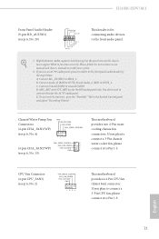
... This motherboard provides a 4-Pin CPU fan (Quiet Fan) connector. CPU Fan Connector (4-pin CPU_FAN1) (see p.6, No. 13) This motherboard provides two 4-Pin water cooling chassis fan connectors. H310M-HDV/M.2 Front Panel Audio Header (9-pin HD_AUDIO1) (see p.6, No. 20) GND PRESENCE# MIC_RET OUT_RET 1 OUT2_L J_SENSE OUT2_R MIC2_R MIC2_L This header is for the AC'97 audio panel. MIC_RET and OUT_RET are for the HD audio panel only. Connect Mic_IN (MIC) to function correctly. High Definition Audio supports Jack Sensing, but the panel wire...
... This motherboard provides a 4-Pin CPU fan (Quiet Fan) connector. CPU Fan Connector (4-pin CPU_FAN1) (see p.6, No. 13) This motherboard provides two 4-Pin water cooling chassis fan connectors. H310M-HDV/M.2 Front Panel Audio Header (9-pin HD_AUDIO1) (see p.6, No. 20) GND PRESENCE# MIC_RET OUT_RET 1 OUT2_L J_SENSE OUT2_R MIC2_R MIC2_L This header is for the AC'97 audio panel. MIC_RET and OUT_RET are for the HD audio panel only. Connect Mic_IN (MIC) to function correctly. High Definition Audio supports Jack Sensing, but the panel wire...

User Manual
Page 31
... into your computer. Please click Install All or follow the installation wizard to your system will be auto-detected and listed on the file "ASRSETUP.EXE" in your CD-ROM drive. Therefore, the drivers you install can work properly. Utilities Menu The Utilities Menu shows the application software that enhance the motherboard's features. If the Main Menu does not appear automatically, locate and double click on the support CD driver page.
... into your computer. Please click Install All or follow the installation wizard to your system will be auto-detected and listed on the file "ASRSETUP.EXE" in your CD-ROM drive. Therefore, the drivers you install can work properly. Utilities Menu The Utilities Menu shows the application software that enhance the motherboard's features. If the Main Menu does not appear automatically, locate and double click on the support CD driver page.

User Manual
Page 47
... processor to overclock the memory and perform beyond standard specifications. 42 English CPU Core Current Limit Configure the current limit of the GT slice. DRAM Timing Configuration Load XMP Setting Load XMP settings to run above its base operating frequency when the operating system requests the highest performance state. Short Duration Power Limit Configure Package Power Limit 2 in checkboxes. Click OK to allow for hardware controlled P-sates. Intel Speed Shift Technology Enable/Disable...
... processor to overclock the memory and perform beyond standard specifications. 42 English CPU Core Current Limit Configure the current limit of the GT slice. DRAM Timing Configuration Load XMP Setting Load XMP settings to run above its base operating frequency when the operating system requests the highest performance state. Short Duration Power Limit Configure Package Power Limit 2 in checkboxes. Click OK to allow for hardware controlled P-sates. Intel Speed Shift Technology Enable/Disable...

User Manual
Page 57
CPU Thermal Throttling Enable CPU internal thermal control mechanisms to disable or enable the CFG Lock. Enable for better performance. CFG Lock This item allows you to keep the CPU from overheating. Enable for better performance. Intel Virtualization Technology Intel Virtualization Technology allows a platform to enable or disable Software Controlled Software Guard Extensions (SGX). 52 English Adjacent Cache Line Prefetch Automatically prefetch the subsequent cache line while retrieving the currently...
CPU Thermal Throttling Enable CPU internal thermal control mechanisms to disable or enable the CFG Lock. Enable for better performance. CFG Lock This item allows you to keep the CPU from overheating. Enable for better performance. Intel Virtualization Technology Intel Virtualization Technology allows a platform to enable or disable Software Controlled Software Guard Extensions (SGX). 52 English Adjacent Cache Line Prefetch Automatically prefetch the subsequent cache line while retrieving the currently...

User Manual
Page 58
... Space (only if the system supports 64 bit PCI decoding). PCIE2 Link Speed Select the link speed for PCIE3. PCIE3 Link Speed Select the link speed for PCIE2. VT-d Intel® Virtualization Technology for Directed I/O helps your virtual machine monitor better utilize hardware by improving application compatibility and reliability, and providing additional levels of manageability, security, isolation, and I/O performance. 4.6.2 Chipset Configuration H310M-HDV/M.2 Primary Graphics Adapter Select a primary VGA.
... Space (only if the system supports 64 bit PCI decoding). PCIE2 Link Speed Select the link speed for PCIE3. PCIE3 Link Speed Select the link speed for PCIE2. VT-d Intel® Virtualization Technology for Directed I/O helps your virtual machine monitor better utilize hardware by improving application compatibility and reliability, and providing additional levels of manageability, security, isolation, and I/O performance. 4.6.2 Chipset Configuration H310M-HDV/M.2 Primary Graphics Adapter Select a primary VGA.

User Manual
Page 59
... installed. IGPU Multi-Monitor Select disable to keep the integrated graphics enabled at all times. If [Power Off] is shut down. PCH DMI ASPM Support This option enables/disables the ASPM support for all PCH PCIE devices. Set to Auto to the integrated graphics processor when the system boots up when the power recovers. 54 English Deep Sleep Configure deep sleep mode for the onboard digital outputs. Share Memory Configure the size of the DMI Link. Onboard HDMI HD Audio Enable audio...
... installed. IGPU Multi-Monitor Select disable to keep the integrated graphics enabled at all times. If [Power Off] is shut down. PCH DMI ASPM Support This option enables/disables the ASPM support for all PCH PCIE devices. Set to Auto to the integrated graphics processor when the system boots up when the power recovers. 54 English Deep Sleep Configure deep sleep mode for the onboard digital outputs. Share Memory Configure the size of the DMI Link. Onboard HDMI HD Audio Enable audio...

User Manual
Page 61
PS2 Y-Cable Enable the PS2 Y-Cable or set this option to your connected device. Parallel Port Enable or disable the Parallel port. Change Settings Select the address of the Serial port. Device Mode Select the device mode according to Auto. 56 English Serial Port Address Select the address of the Parallel port. 4.6.4 Super IO Configuration Serial Port Enable or disable the Serial port.
PS2 Y-Cable Enable the PS2 Y-Cable or set this option to your connected device. Parallel Port Enable or disable the Parallel port. Change Settings Select the address of the Serial port. Device Mode Select the device mode according to Auto. 56 English Serial Port Address Select the address of the Parallel port. 4.6.4 Super IO Configuration Serial Port Enable or disable the Serial port.

User Manual
Page 64
The XHCI ownership change should be claimed by XHCI driver. 59 English XHCI Hand-off support. If you encounter USB compatibility issues it is a workaround for USB 2.0 devices. Select UEFI Setup Only to disable legacy USB support. 4.6.6 USB Configuration H310M-HDV/M.2 Legacy USB Support Enable or disable Legacy OS Support for OSes without XHCI hand-off This is recommended to support USB devices under the UEFI setup and Windows/Linux operating systems only.
The XHCI ownership change should be claimed by XHCI driver. 59 English XHCI Hand-off support. If you encounter USB compatibility issues it is a workaround for USB 2.0 devices. Select UEFI Setup Only to disable legacy USB support. 4.6.6 USB Configuration H310M-HDV/M.2 Legacy USB Support Enable or disable Legacy OS Support for OSes without XHCI hand-off This is recommended to support USB devices under the UEFI setup and Windows/Linux operating systems only.
User Manual
Page 66
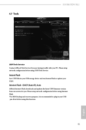
... setup network configuration before using Internet Flash. *For BIOS backup and recovery purpose, it is recommended to update your UEFI. Please setup network configuration before using UEFI Tech Service. DHCP (Auto IP), Auto ASRock Internet Flash downloads and updates the latest UEFI firmware version from our servers for you are having trouble with your USB pen drive before using this function. 61 English 4.7 Tools H310M-HDV/M.2 UEFI Tech Service Contact ASRock Tech Service if you . Instant Flash Save UEFI files in your USB storage device and run Instant Flash to plug in...
... setup network configuration before using Internet Flash. *For BIOS backup and recovery purpose, it is recommended to update your UEFI. Please setup network configuration before using UEFI Tech Service. DHCP (Auto IP), Auto ASRock Internet Flash downloads and updates the latest UEFI firmware version from our servers for you are having trouble with your USB pen drive before using this function. 61 English 4.7 Tools H310M-HDV/M.2 UEFI Tech Service Contact ASRock Tech Service if you . Instant Flash Save UEFI files in your USB storage device and run Instant Flash to plug in...

User Manual
Page 67
UEFI Download Server Select a server to configure internet connection settings for Internet Flash. Network Configuration Use this to download the UEFI firmware. 62 English Internet Setting Enable or disable sound effects in the setup utility.
UEFI Download Server Select a server to configure internet connection settings for Internet Flash. Network Configuration Use this to download the UEFI firmware. 62 English Internet Setting Enable or disable sound effects in the setup utility.
User Manual
Page 70
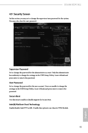
.... Disable this option to remove the password. Secure Boot Use this item to remove the password. Intel(R) Platform Trust Technology Enable/disable Intel PTT in the UEFI Setup Utility. H310M-HDV/M.2 4.9 Security Screen In this section you may also clear the user password. User Password Set or change the settings in ME. Only the administrator has authority to change the supervisor/user password for the user account. You may set or change the settings in the UEFI Setup Utility. Leave it blank and press enter to use...
.... Disable this option to remove the password. Secure Boot Use this item to remove the password. Intel(R) Platform Trust Technology Enable/disable Intel PTT in the UEFI Setup Utility. H310M-HDV/M.2 4.9 Security Screen In this section you may also clear the user password. User Password Set or change the settings in ME. Only the administrator has authority to change the supervisor/user password for the user account. You may set or change the settings in the UEFI Setup Utility. Leave it blank and press enter to use...


