

User Manual
Page 2
... consent of this documentation may be constructed as a commitment by the purchaser for a particular purpose. Copyright Notice: No part of ASRock Inc. With respect to the owners' benefit, without notice, and should not be reproduced, transcribed, transmitted, or translated in any...of any defect or error in this documentation may or may cause undesired operation. This device complies with Part 15 of this motherboard contains Perchlorate, a toxic substance controlled in Perchlorate Best Management Practices (BMP) regulations passed by the California Legislature. All rights ...
... consent of this documentation may be constructed as a commitment by the purchaser for a particular purpose. Copyright Notice: No part of ASRock Inc. With respect to the owners' benefit, without notice, and should not be reproduced, transcribed, transmitted, or translated in any...of any defect or error in this documentation may or may cause undesired operation. This device complies with Part 15 of this motherboard contains Perchlorate, a toxic substance controlled in Perchlorate Best Management Practices (BMP) regulations passed by the California Legislature. All rights ...
User Manual
Page 4
...Motherboard Layout 6 1.4 I/O Panel 8 Chapter 2 Installation 10 2.1 Installing the CPU 11 2.2 Installing the CPU Fan and Heatsink 14 2.3 Installing Memory Modules (DIMM) 15 2.4 Expansion Slots (PCI Express Slots) 17 2.5 Jumpers Setup 18 2.6 Onboard Headers and Connectors 19 Chapter 3 Software and Utilities Operation 27 3.1 Installing Drivers 27 3.2 A-Tuning 28 3.3 ASRock... Live Update & APP Shop 31 3.3.1 UI Overview 31 3.3.2 Apps 32 3.3.3 BIOS & Drivers 35 3.3.4 Setting 36 3.4 ASRock RGB LED 37
...Motherboard Layout 6 1.4 I/O Panel 8 Chapter 2 Installation 10 2.1 Installing the CPU 11 2.2 Installing the CPU Fan and Heatsink 14 2.3 Installing Memory Modules (DIMM) 15 2.4 Expansion Slots (PCI Express Slots) 17 2.5 Jumpers Setup 18 2.6 Onboard Headers and Connectors 19 Chapter 3 Software and Utilities Operation 27 3.1 Installing Drivers 27 3.2 A-Tuning 28 3.3 ASRock... Live Update & APP Shop 31 3.3.1 UI Overview 31 3.3.2 Apps 32 3.3.3 BIOS & Drivers 35 3.3.4 Setting 36 3.4 ASRock RGB LED 37
User Manual
Page 6
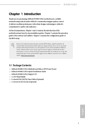
... well. If you for M.2 Socket (Optional) 1 English ASRock website http://www.asrock.com. 1.1 Package Contents • ASRock H310M-G/M.2 Motherboard (Micro ATX Form Factor) • ASRock H310M-G/M.2 Quick Installation Guide • ASRock H310M-G/M.2 Support CD • 1 x I/O Panel Shield • 2 x Serial ATA (SATA) Data Cables (Optional) • 1 x Screw for purchasing ASRock H310M-G/M.2 motherboard, a reliable motherboard produced under ASRock's consistently stringent quality control. You may find the...
... well. If you for M.2 Socket (Optional) 1 English ASRock website http://www.asrock.com. 1.1 Package Contents • ASRock H310M-G/M.2 Motherboard (Micro ATX Form Factor) • ASRock H310M-G/M.2 Quick Installation Guide • ASRock H310M-G/M.2 Support CD • 1 x I/O Panel Shield • 2 x Serial ATA (SATA) Data Cables (Optional) • 1 x Screw for purchasing ASRock H310M-G/M.2 motherboard, a reliable motherboard produced under ASRock's consistently stringent quality control. You may find the...

User Manual
Page 11
... 1.3 Motherboard Layout 1 ATX12V1 2 3 4 CPU_FAN1 CHA_FAN1/WP 5 VGA1 DVI1 ATXPWR1 DDR4_A1 (64 bit, 288-pin module) DDR4_B1 (64 bit, 288-pin module) HDMI1 USB 3.1 Gen1 T: USB3 B: USB4 USB 2.0 T: USB5 B: USB6 Top: RJ-45 LAN Top: LINE IN Center: FRONT Bottom: MIC IN AUDIO CODEC Intel H310 CMOS Battery PCIE1 BIOS ROM PCIE2 H310M...
... 1.3 Motherboard Layout 1 ATX12V1 2 3 4 CPU_FAN1 CHA_FAN1/WP 5 VGA1 DVI1 ATXPWR1 DDR4_A1 (64 bit, 288-pin module) DDR4_B1 (64 bit, 288-pin module) HDMI1 USB 3.1 Gen1 T: USB3 B: USB4 USB 2.0 T: USB5 B: USB6 Top: RJ-45 LAN Top: LINE IN Center: FRONT Bottom: MIC IN AUDIO CODEC Intel H310 CMOS Battery PCIE1 BIOS ROM PCIE2 H310M...

User Manual
Page 15
... and do not overtighten the screws! Doing so may cause physical injuries and damages to motherboard components. • In order to avoid damage from static electricity to the motherboard's components, NEVER place your chassis to the chassis, please do not touch the ICs.... the following precautions before installing or removing the motherboard components. Chapter 2 Installation This is a Micro ATX form factor motherboard. Failure to do so may damage the motherboard. 10 English Pre-installation Precautions Take note of your motherboard directly on a grounded anti-static pad or...
... and do not overtighten the screws! Doing so may cause physical injuries and damages to motherboard components. • In order to avoid damage from static electricity to the motherboard's components, NEVER place your chassis to the chassis, please do not touch the ICs.... the following precautions before installing or removing the motherboard components. Chapter 2 Installation This is a Micro ATX form factor motherboard. Failure to do so may damage the motherboard. 10 English Pre-installation Precautions Take note of your motherboard directly on a grounded anti-static pad or...

User Manual
Page 18
H310M-G/M.2 Please save and replace the cover if the processor is removed. The cover must be placed if you wish to return the motherboard for after service. 13 English
H310M-G/M.2 Please save and replace the cover if the processor is removed. The cover must be placed if you wish to return the motherboard for after service. 13 English

User Manual
Page 20
... DIMM may be damaged. It will cause permanent damage to the motherboard and the DIMM if you always need to install identical (the same brand, speed, size and chip-type) DDR4 DIMM pairs. 2. For dual channel configuration, ... Technology with only one correct orientation. It is unable to install a DDR, DDR2 or DDR3 memory module into the slot at incorrect orientation. 15 English H310M-G/M.2 2.3 Installing Memory Modules (DIMM) This motherboard provides two 288-pin DDR4 (Double Data Rate 4) DIMM slots, and supports Dual Channel Memory Technology. 1.
... DIMM may be damaged. It will cause permanent damage to the motherboard and the DIMM if you always need to install identical (the same brand, speed, size and chip-type) DDR4 DIMM pairs. 2. For dual channel configuration, ... Technology with only one correct orientation. It is unable to install a DDR, DDR2 or DDR3 memory module into the slot at incorrect orientation. 15 English H310M-G/M.2 2.3 Installing Memory Modules (DIMM) This motherboard provides two 288-pin DDR4 (Double Data Rate 4) DIMM slots, and supports Dual Channel Memory Technology. 1.

User Manual
Page 22
... unplugged. Before installing an expansion card, please make necessary hardware settings for PCI Express x16 lane width graphics cards. H310M-G/M.2 2.4 Expansion Slots (PCI Express Slots) There are 3 PCI Express slots on the motherboard. PCIE2 (PCIe 3.0 x16 slot) is used for PCI Express x1 lane width cards. 17 English PCIe slots: PCIE1 (PCIe...
... unplugged. Before installing an expansion card, please make necessary hardware settings for PCI Express x16 lane width graphics cards. H310M-G/M.2 2.4 Expansion Slots (PCI Express Slots) There are 3 PCI Express slots on the motherboard. PCIE2 (PCIe 3.0 x16 slot) is used for PCI Express x1 lane width cards. 17 English PCIe slots: PCIE1 (PCIe...

User Manual
Page 24
... differ by chassis. The LED is on when the hard drive is operating. The front panel design may configure the way to the motherboard. When connecting your system using the power button. PLED (System Power LED): Connect to this header according to the reset button on ...chassis front panel module to the power status indicator on the chassis front panel. RESET (Reset Button): Connect to the pin assignments below. H310M-G/M.2 2.6 Onboard Headers and Connectors Onboard headers and connectors are matched correctly. Do NOT place jumper caps over the headers and connectors will ...
... differ by chassis. The LED is on when the hard drive is operating. The front panel design may configure the way to the motherboard. When connecting your system using the power button. PLED (System Power LED): Connect to this header according to the reset button on ...chassis front panel module to the power status indicator on the chassis front panel. RESET (Reset Button): Connect to the pin assignments below. H310M-G/M.2 2.6 Onboard Headers and Connectors Onboard headers and connectors are matched correctly. Do NOT place jumper caps over the headers and connectors will ...

User Manual
Page 25
Vbus V IntA_PA_D+ IntA_PA_DGND IntA_PA_SSTX+ IntA_PA_SSTXGND IntA_PA_SSRX+ IntA_PA_SSRXbus There is shared with up to this motherboard. This USB 3.1 Gen1 header can support two ports. (9-pin USB_9_10) (see p.6, No. 7) 1 Dummy IntA_PB_D+ IntA_PB_D- ...SATA3_2: see p.6, No. 8) (SATA3_3: see p.6, No. 16) USB_PWR PP+ GND DUMMY 1 GND P+ PUSB_PWR There are two USB 2.0 headers on this motherboard. GND IntA_PB_SSTX+ IntA_PB_SSTX- USB 2.0 Headers (9-pin USB_7_8) (see p.6, No. 9) SATA3_0 SATA3_2 SATA3_1 SATA3_3 These four SATA3 connectors support SATA data cables for internal...
Vbus V IntA_PA_D+ IntA_PA_DGND IntA_PA_SSTX+ IntA_PA_SSTXGND IntA_PA_SSRX+ IntA_PA_SSRXbus There is shared with up to this motherboard. This USB 3.1 Gen1 header can support two ports. (9-pin USB_9_10) (see p.6, No. 7) 1 Dummy IntA_PB_D+ IntA_PB_D- ...SATA3_2: see p.6, No. 8) (SATA3_3: see p.6, No. 16) USB_PWR PP+ GND DUMMY 1 GND P+ PUSB_PWR There are two USB 2.0 headers on this motherboard. GND IntA_PB_SSTX+ IntA_PB_SSTX- USB 2.0 Headers (9-pin USB_7_8) (see p.6, No. 9) SATA3_0 SATA3_2 SATA3_1 SATA3_3 These four SATA3 connectors support SATA data cables for internal...

User Manual
Page 26
H310M-G/M.2 Front Panel Audio Header (9-pin HD_AUDIO1) (see p.6, No. 22) GND PRESENCE# MIC_RET OUT_RET 1 OUT2_L J_SENSE OUT2_R MIC2_R MIC2_L This header is for connecting ... CHA_FAN1/WP) (see p.6, No. 4) GND FAN_VOLTAGE FAN_SPEED FAN_SPEED_CONTROL 1 2 34 FAN_SPEED_CONTROL 4 CHA_FAN_SPEED 3 (4-pin CHA_FAN2/WP) FAN_VOLTAGE 2 GND 1 (see p.6, No. 2) FAN_SPEED_CONTROL CPU_FAN_SPEED FAN_VOLTAGE GND 1 2 34 This motherboard provides a 4-Pin CPU fan (Quiet Fan) connector. E. Connect Mic_IN (MIC) to Ground (GND). High Definition Audio supports Jack Sensing, but the panel wire on the...
H310M-G/M.2 Front Panel Audio Header (9-pin HD_AUDIO1) (see p.6, No. 22) GND PRESENCE# MIC_RET OUT_RET 1 OUT2_L J_SENSE OUT2_R MIC2_R MIC2_L This header is for connecting ... CHA_FAN1/WP) (see p.6, No. 4) GND FAN_VOLTAGE FAN_SPEED FAN_SPEED_CONTROL 1 2 34 FAN_SPEED_CONTROL 4 CHA_FAN_SPEED 3 (4-pin CHA_FAN2/WP) FAN_VOLTAGE 2 GND 1 (see p.6, No. 2) FAN_SPEED_CONTROL CPU_FAN_SPEED FAN_VOLTAGE GND 1 2 34 This motherboard provides a 4-Pin CPU fan (Quiet Fan) connector. E. Connect Mic_IN (MIC) to Ground (GND). High Definition Audio supports Jack Sensing, but the panel wire on the...

User Manual
Page 27
... BUSY SPD4 PE SPD3 SLCT SPD2 SPD1 SPD0 STB# This is an interface for print port cable that allows convenient connection of printer devices. This motherboard provides an 8-pin ATX 12V power connector. ATX Power Connector (24-pin ATXPWR1) (see p.6, No. 5) 12 24 ATX 12V Power Connector (8-pin ATX12V1) (see p.6, No...
... BUSY SPD4 PE SPD3 SLCT SPD2 SPD1 SPD0 STB# This is an interface for print port cable that allows convenient connection of printer devices. This motherboard provides an 8-pin ATX 12V power connector. ATX Power Connector (24-pin ATXPWR1) (see p.6, No. 5) 12 24 ATX 12V Power Connector (8-pin ATX12V1) (see p.6, No...

User Manual
Page 30
... straight to Step 5 if you are going to secure the module into place. Step 4 Peel off the yellow protective film on the motherboard. Please be used. Please do not overtighten the screw as this might damage the module. 25 English The standoff is placed at the...be aware that the M.2 (NGFF) SSD module only fits in one orientation. Hand tighten the standoff into the M.2 slot. D C B A D C B A D C B A H310M-G/M.2 Step 3 Move the standoff based on the module type and length. D C B A 20o D NUT2 NUT1 Step 6 Tighten the screw with a screwdriver to use the default nut....
... straight to Step 5 if you are going to secure the module into place. Step 4 Peel off the yellow protective film on the motherboard. Please be used. Please do not overtighten the screw as this might damage the module. 25 English The standoff is placed at the...be aware that the M.2 (NGFF) SSD module only fits in one orientation. Hand tighten the standoff into the M.2 slot. D C B A D C B A D C B A H310M-G/M.2 Step 3 Move the standoff based on the module type and length. D C B A 20o D NUT2 NUT1 Step 6 Tighten the screw with a screwdriver to use the default nut....
User Manual
Page 32
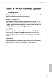
... bottom to install it. 27 English Therefore, the drivers you install can work properly. H310M-G/M.2 Chapter 3 Software and Utilities Operation 3.1 Installing Drivers The Support CD that comes with the motherboard contains necessary drivers and useful utilities that the motherboard supports. Please click Install All or follow the installation wizard to install those required...
... bottom to install it. 27 English Therefore, the drivers you install can work properly. H310M-G/M.2 Chapter 3 Software and Utilities Operation 3.1 Installing Drivers The Support CD that comes with the motherboard contains necessary drivers and useful utilities that the motherboard supports. Please click Install All or follow the installation wizard to install those required...

User Manual
Page 36
H310M-G/M.2 3.3 ASRock Live Update & APP Shop The ASRock Live Update & APP Shop is an online store for purchasing and downloading software applications for your desktop to access ASRock Live Update & APP Shop *You need to be connected to the Internet to download apps from the ASRock Live Update & APP Shop. ...and know more. 31 English You can optimize your system and keep your motherboard up to date simply with a few clicks. on the image to perform job-related tasks. Click on your ASRock computer. With ASRock Live Update & APP Shop, you can quickly and easily install various ...
H310M-G/M.2 3.3 ASRock Live Update & APP Shop The ASRock Live Update & APP Shop is an online store for purchasing and downloading software applications for your desktop to access ASRock Live Update & APP Shop *You need to be connected to the Internet to download apps from the ASRock Live Update & APP Shop. ...and know more. 31 English You can optimize your system and keep your motherboard up to date simply with a few clicks. on the image to perform job-related tasks. Click on your ASRock computer. With ASRock Live Update & APP Shop, you can quickly and easily install various ...

User Manual
Page 42
...Never install the RGB LED cable in the wrong orientation; RGB_LED1 1 12V G R B H310M-G/M.2 1 B 12V G R 1. Please note that the RGB LED strips do so may be damaged. 2. Failure to motherboard components. 1. otherwise, the cable may cause damages to do not come with a maximum power... colorful lighting system. The RGB LED header supports standard 5050 RGB LED strip (12V/G/R/B), with the package. 2. H310M-G/M.2 3.4 ASRock RGB LED ASRock RGB LED is a lighting control utility specifically designed for unique individuals with sophisticated tastes to the RGB LED Header (RGB_LED1...
...Never install the RGB LED cable in the wrong orientation; RGB_LED1 1 12V G R B H310M-G/M.2 1 B 12V G R 1. Please note that the RGB LED strips do so may be damaged. 2. Failure to motherboard components. 1. otherwise, the cable may cause damages to do not come with a maximum power... colorful lighting system. The RGB LED header supports standard 5050 RGB LED strip (12V/G/R/B), with the package. 2. H310M-G/M.2 3.4 ASRock RGB LED ASRock RGB LED is a lighting control utility specifically designed for unique individuals with sophisticated tastes to the RGB LED Header (RGB_LED1...

User Manual
Page 43
... unplug the power cord from the power supply. Before installing or removing your RGB LED cable, please power off your Addressable RGB LED strip to motherboard components. 1. Please note that the RGB LED strips do so may be damaged. 2. Failure to do not come with a maximum power rating of 3A (5V...
... unplug the power cord from the power supply. Before installing or removing your RGB LED cable, please power off your Addressable RGB LED strip to motherboard components. 1. Please note that the RGB LED strips do so may be damaged. 2. Failure to do not come with a maximum power rating of 3A (5V...

User Manual
Page 44
Toggle on/off the RGB LED switch Sync RGB LED effects for all LED regions of the motherboard Select a RGB LED light effect from the ASRock Live Update & APP Shop and start coloring your PC style your preference. English 39 Download this utility from the drop-down menu. Drag the tab to customize your way! H310M-G/M.2 ASRock RGB LED Utility Now you can adjust the RGB LED color through the ASRock RGB LED utility.
Toggle on/off the RGB LED switch Sync RGB LED effects for all LED regions of the motherboard Select a RGB LED light effect from the ASRock Live Update & APP Shop and start coloring your PC style your preference. English 39 Download this utility from the drop-down menu. Drag the tab to customize your way! H310M-G/M.2 ASRock RGB LED Utility Now you can adjust the RGB LED color through the ASRock RGB LED utility.

User Manual
Page 52
...and the beginning of clock cycles required between the opening the next row. DRAM Clock controls memory training only if ASRock Timing Optimization is selected, the motherboard will detect the memory module(s) inserted and assign the appropriate frequency automatically. Primary Timing CAS# Latency (tCL) ...The time between sending a column address to the same rank. 47 English RAS# Active Time (tRAS) The number of the data in response. H310M-G/M.2 ...
...and the beginning of clock cycles required between the opening the next row. DRAM Clock controls memory training only if ASRock Timing Optimization is selected, the motherboard will detect the memory module(s) inserted and assign the appropriate frequency automatically. Primary Timing CAS# Latency (tCL) ...The time between sending a column address to the same rank. 47 English RAS# Active Time (tRAS) The number of the data in response. H310M-G/M.2 ...

User Manual
Page 72
... a fan mode for CPU Fans 1&2, or choose Customize to monitor the status of the hardware on your system, including the parameters of the CPU temperature, motherboard temperature, fan speed and voltage. CPU Fan Step Down Set the value of CPU Fan Step Up. CPU Fan Step Up Set the value of... CPU Fan Step Down. Fan Tuning Measure Fan Min Duty Cycle. H310M-G/M.2 4.8 Hardware Health Event Monitoring Screen This section allows you to set 5 CPU temperatures and assign a respective fan speed for each temperature.
... a fan mode for CPU Fans 1&2, or choose Customize to monitor the status of the hardware on your system, including the parameters of the CPU temperature, motherboard temperature, fan speed and voltage. CPU Fan Step Down Set the value of CPU Fan Step Up. CPU Fan Step Up Set the value of... CPU Fan Step Down. Fan Tuning Measure Fan Min Duty Cycle. H310M-G/M.2 4.8 Hardware Health Event Monitoring Screen This section allows you to set 5 CPU temperatures and assign a respective fan speed for each temperature.


