
User Manual
Page 4
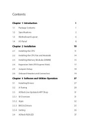
...Introduction 1 1.1 Package Contents 1 1.2 Specifications 2 1.3 Motherboard Layout 6 1.4 I/O Panel 8 Chapter 2 Installation 10 2.1 Installing the CPU 11 2.2 Installing the CPU Fan and Heatsink 14 2.3 Installing Memory Modules (DIMM) 15 2.4 Expansion Slots (PCI Express Slots) 17 2.5 Jumpers Setup 18 2.6 Onboard Headers and Connectors 19 Chapter 3 Software and Utilities Operation 27 3.1 Installing Drivers 27 3.2 A-Tuning 28 3.3 ASRock Live Update & APP Shop 31 3.3.1 UI Overview 31 3.3.2 Apps 32 3.3.3 BIOS & Drivers 35 3.3.4 Setting 36 3.4 ASRock RGB LED 37
...Introduction 1 1.1 Package Contents 1 1.2 Specifications 2 1.3 Motherboard Layout 6 1.4 I/O Panel 8 Chapter 2 Installation 10 2.1 Installing the CPU 11 2.2 Installing the CPU Fan and Heatsink 14 2.3 Installing Memory Modules (DIMM) 15 2.4 Expansion Slots (PCI Express Slots) 17 2.5 Jumpers Setup 18 2.6 Onboard Headers and Connectors 19 Chapter 3 Software and Utilities Operation 27 3.1 Installing Drivers 27 3.2 A-Tuning 28 3.3 ASRock Live Update & APP Shop 31 3.3.1 UI Overview 31 3.3.2 Apps 32 3.3.3 BIOS & Drivers 35 3.3.4 Setting 36 3.4 ASRock RGB LED 37
User Manual
Page 6
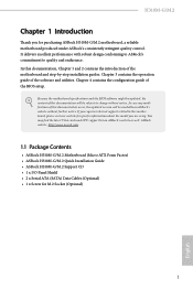
...Guide • ASRock H310M-G/M.2 Support CD • 1 x I/O Panel Shield • 2 x Serial ATA (SATA) Data Cables (Optional) • 1 x Screw for purchasing ASRock H310M-G/M.2 motherboard, a reliable motherboard produced under ASRock's consistently stringent quality control. You may find the latest VGA cards and CPU support list on ASRock's website without notice. Chapter 4 contains the configuration guide of the software and utilities. In case any modifications of the motherboard and step-by-step installation guides. Chapter 3 contains the operation guide of the BIOS setup...
...Guide • ASRock H310M-G/M.2 Support CD • 1 x I/O Panel Shield • 2 x Serial ATA (SATA) Data Cables (Optional) • 1 x Screw for purchasing ASRock H310M-G/M.2 motherboard, a reliable motherboard produced under ASRock's consistently stringent quality control. You may find the latest VGA cards and CPU support list on ASRock's website without notice. Chapter 4 contains the configuration guide of the software and utilities. In case any modifications of the motherboard and step-by-step installation guides. Chapter 3 contains the operation guide of the BIOS setup...

User Manual
Page 7
...; Turbo Boost 2.0 Technology Chipset • Intel® H310 Memory • Dual Channel DDR4 Memory Technology • 2 x DDR4 DIMM Slots • Supports DDR4 2666/2400/2133 non-ECC, un-buffered memory • Max. capacity of system memory: 32GB • Supports Intel® Extreme Memory Profile (XMP) 2.0 • 15μ Gold Contact in DIMM Slots Expansion Slot • 1 x PCI Express 3.0 x16 Slot (PCIE1: x16 mode)* * Supports NVMe SSD as boot disks • 2 x PCI Express 2.0 x1 Slots Graphics • Intel...
...; Turbo Boost 2.0 Technology Chipset • Intel® H310 Memory • Dual Channel DDR4 Memory Technology • 2 x DDR4 DIMM Slots • Supports DDR4 2666/2400/2133 non-ECC, un-buffered memory • Max. capacity of system memory: 32GB • Supports Intel® Extreme Memory Profile (XMP) 2.0 • 15μ Gold Contact in DIMM Slots Expansion Slot • 1 x PCI Express 3.0 x16 Slot (PCIE1: x16 mode)* * Supports NVMe SSD as boot disks • 2 x PCI Express 2.0 x1 Slots Graphics • Intel...

User Manual
Page 8
... enable the multi-channel audio feature through the audio driver. • Supports Surge Protection • ELNA Audio Caps LAN • Gigabit LAN 10/100/1000 Mb/s • Giga PHY Intel® I219V • Supports Wake-On-LAN • Supports Lightning/ESD Protection • Supports Energy Efficient Ethernet 802.3az • Supports PXE Rear Panel I/O • 1 x PS/2 Mouse/Keyboard Port • 1 x D-Sub Port • 1 x DVI-D Port • 1 x HDMI Port • 4 x USB 2.0 Ports (Supports ESD Protection) • 2 x USB 3.1 Gen1 Ports (Supports...
... enable the multi-channel audio feature through the audio driver. • Supports Surge Protection • ELNA Audio Caps LAN • Gigabit LAN 10/100/1000 Mb/s • Giga PHY Intel® I219V • Supports Wake-On-LAN • Supports Lightning/ESD Protection • Supports Energy Efficient Ethernet 802.3az • Supports PXE Rear Panel I/O • 1 x PS/2 Mouse/Keyboard Port • 1 x D-Sub Port • 1 x DVI-D Port • 1 x HDMI Port • 4 x USB 2.0 Ports (Supports ESD Protection) • 2 x USB 3.1 Gen1 Ports (Supports...

User Manual
Page 9
... PCI Express module up to Gen2 x4 (20 Gb/s)** ** Supports NVMe SSD as boot disks ** Supports ASRock U.2 Kit Connector • 1 x Print Port Header • 1 x COM Port Header • 1 x TPM Header • 1 x Chassis Intrusion and Speaker Header • 1 x RGB LED Header * Supports in total up to 5V/3A, 15W LED Strip • 1 x Addressable LED Header * Supports in total up to 12V/3A, 36W LED Strip • 1 x CPU Fan Connector (4-pin) * The CPU Fan Connector supports the CPU fan of maximum 1A (12W) fan power. • 2 x Chassis/Water Pump Fan Connectors (4-pin) (Smart Fan Speed Control...
... PCI Express module up to Gen2 x4 (20 Gb/s)** ** Supports NVMe SSD as boot disks ** Supports ASRock U.2 Kit Connector • 1 x Print Port Header • 1 x COM Port Header • 1 x TPM Header • 1 x Chassis Intrusion and Speaker Header • 1 x RGB LED Header * Supports in total up to 5V/3A, 15W LED Strip • 1 x Addressable LED Header * Supports in total up to 12V/3A, 36W LED Strip • 1 x CPU Fan Connector (4-pin) * The CPU Fan Connector supports the CPU fan of maximum 1A (12W) fan power. • 2 x Chassis/Water Pump Fan Connectors (4-pin) (Smart Fan Speed Control...
User Manual
Page 10
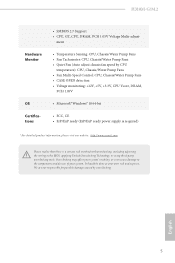
... damage caused by CPU temperature): CPU, Chassis/Water Pump Fans • Fan Multi-Speed Control: CPU, Chassis/Water Pump Fans • CASE OPEN detection • Voltage monitoring: +12V, +5V, +3.3V, CPU Vcore, DRAM, PCH 1.05V • Microsoft® Windows® 10 64-bit • FCC, CE • ErP/EuP ready (ErP/EuP ready power supply is required) * For detailed product information, please visit our website: http://www.asrock.com Please realize...
... damage caused by CPU temperature): CPU, Chassis/Water Pump Fans • Fan Multi-Speed Control: CPU, Chassis/Water Pump Fans • CASE OPEN detection • Voltage monitoring: +12V, +5V, +3.3V, CPU Vcore, DRAM, PCH 1.05V • Microsoft® Windows® 10 64-bit • FCC, CE • ErP/EuP ready (ErP/EuP ready power supply is required) * For detailed product information, please visit our website: http://www.asrock.com Please realize...

User Manual
Page 12
...pin DDR4 DIMM Slots (DDR4_A1, DDR4_B1) 4 Chassis/Water Pump Fan Connector (CHA_FAN1/WP) 5 ATX Power Connector (ATXPWR1) 6 USB 2.0 Header (USB_9_10) 7 USB 3.1 Gen1 Header (USB_11_12) 8 SATA3 Connector (SATA3_2) 9 SATA3 Connector (SATA3_3) 10 Clear CMOS Jumper (CLRMOS1) 11 SATA3 Connector (SATA3_0) 12 SATA3 Connector (SATA3_1) 13 Chassis/Water Pump Fan Connector (CHA_FAN2/WP) 14 System Panel Header (PANEL1) 15 Chassis Intrusion and Speaker Header (SPK_CI1) 16 USB 2.0 Header (USB_7_8) 17 Addressable LED Header (ADDR_LED1) 18 RGB LED Header (RGB_LED1) 19 COM Port Header (COM1) 20 Print Port Header...
...pin DDR4 DIMM Slots (DDR4_A1, DDR4_B1) 4 Chassis/Water Pump Fan Connector (CHA_FAN1/WP) 5 ATX Power Connector (ATXPWR1) 6 USB 2.0 Header (USB_9_10) 7 USB 3.1 Gen1 Header (USB_11_12) 8 SATA3 Connector (SATA3_2) 9 SATA3 Connector (SATA3_3) 10 Clear CMOS Jumper (CLRMOS1) 11 SATA3 Connector (SATA3_0) 12 SATA3 Connector (SATA3_1) 13 Chassis/Water Pump Fan Connector (CHA_FAN2/WP) 14 System Panel Header (PANEL1) 15 Chassis Intrusion and Speaker Header (SPK_CI1) 16 USB 2.0 Header (USB_7_8) 17 Addressable LED Header (ADDR_LED1) 18 RGB LED Header (RGB_LED1) 19 COM Port Header (COM1) 20 Print Port Header...

User Manual
Page 22
... PCIE3 (PCIe 2.0 x1 slot) is used for PCI Express x1 lane width cards. PCIE2 (PCIe 3.0 x16 slot) is unplugged. Please read the documentation of the expansion card and make sure that the power supply is switched off or the power cord is used for the card before you start the installation. Before installing an expansion card, please make necessary hardware settings for PCI Express x16 lane width graphics cards. H310M-G/M.2 2.4 Expansion Slots (PCI Express Slots) There are 3 PCI Express slots on the motherboard.
... PCIE3 (PCIe 2.0 x1 slot) is used for PCI Express x1 lane width cards. PCIE2 (PCIe 3.0 x16 slot) is unplugged. Please read the documentation of the expansion card and make sure that the power supply is switched off or the power cord is used for the card before you start the installation. Before installing an expansion card, please make necessary hardware settings for PCI Express x16 lane width graphics cards. H310M-G/M.2 2.4 Expansion Slots (PCI Express Slots) There are 3 PCI Express slots on the motherboard.

User Manual
Page 23
... 3 seconds. If no jumper cap is placed on the pins, the jumper is "Open". Clear CMOS Jumper (CLRCMOS1) (see p.6, No. 10) 2-pin Jumper Short: Clear CMOS Open: Default CLRCMOS1 allows you do the clear-CMOS action. To clear and reset the system parameters to default setup, please turn off the computer and unplug the power cord, then use a jumper cap to clear the CMOS when you just finish updating the BIOS, you must boot up the system...
... 3 seconds. If no jumper cap is placed on the pins, the jumper is "Open". Clear CMOS Jumper (CLRCMOS1) (see p.6, No. 10) 2-pin Jumper Short: Clear CMOS Open: Default CLRCMOS1 allows you do the clear-CMOS action. To clear and reset the system parameters to default setup, please turn off the computer and unplug the power cord, then use a jumper cap to clear the CMOS when you just finish updating the BIOS, you must boot up the system...

User Manual
Page 24
... connecting your system using the power button. You may differ by chassis. RESET (Reset Button): Connect to the reset button on the chassis to this header, make sure the wire assignments and the pin assignments are NOT jumpers. The LED is on when the hard drive is operating. Placing jumper caps over these headers and connectors. The LED is on when the system is reading or writing data. A front panel module mainly consists of power button, reset button, power LED, hard drive activity LED, speaker...
... connecting your system using the power button. You may differ by chassis. RESET (Reset Button): Connect to the reset button on the chassis to this header, make sure the wire assignments and the pin assignments are NOT jumpers. The LED is on when the hard drive is operating. Placing jumper caps over these headers and connectors. The LED is on when the system is reading or writing data. A front panel module mainly consists of power button, reset button, power LED, hard drive activity LED, speaker...
User Manual
Page 32
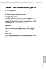
... auto-detected and listed on the support CD driver page. Please click Install All or follow the installation wizard to display the menu. Utilities Menu The Utilities Menu shows the application software that enhance the motherboard's features. Running The Support CD To begin using the support CD, insert the CD into your computer. Click on the file "ASRSETUP.EXE" in your CD-ROM drive. Therefore, the drivers you install can work properly. H310M-G/M.2 Chapter 3 Software...
... auto-detected and listed on the support CD driver page. Please click Install All or follow the installation wizard to display the menu. Utilities Menu The Utilities Menu shows the application software that enhance the motherboard's features. Running The Support CD To begin using the support CD, insert the CD into your computer. Click on the file "ASRSETUP.EXE" in your CD-ROM drive. Therefore, the drivers you install can work properly. H310M-G/M.2 Chapter 3 Software...

User Manual
Page 61
... line while retrieving the currently requested cache line. CPU Thermal Throttling Enable CPU internal thermal control mechanisms to run multiple operating systems and applications in independent partitions, so that one computer system can function as multiple virtual systems. Hardware Prefetcher Automatically prefetch data and code for the processor. Enable for better performance. Intel Virtualization Technology Intel Virtualization Technology allows a platform to keep the...
... line while retrieving the currently requested cache line. CPU Thermal Throttling Enable CPU internal thermal control mechanisms to run multiple operating systems and applications in independent partitions, so that one computer system can function as multiple virtual systems. Hardware Prefetcher Automatically prefetch data and code for the processor. Enable for better performance. Intel Virtualization Technology Intel Virtualization Technology allows a platform to keep the...

User Manual
Page 62
Above 4G Decoding Enable or disable 64bit capable Devices to be decoded in OS. 57 English PCI Express Native Control Select Enable for enhanced PCI Express power saving in Above 4G Address Space (only if the system supports 64 bit PCI decoding). VT-d Intel® Virtualization Technology for PCIE1. PCIE1 Link Speed Select the link speed for Directed I/O helps your virtual machine monitor better utilize hardware by improving application compatibility and reliability...
Above 4G Decoding Enable or disable 64bit capable Devices to be decoded in OS. 57 English PCI Express Native Control Select Enable for enhanced PCI Express power saving in Above 4G Address Space (only if the system supports 64 bit PCI decoding). VT-d Intel® Virtualization Technology for PCIE1. PCIE1 Link Speed Select the link speed for Directed I/O helps your virtual machine monitor better utilize hardware by improving application compatibility and reliability...

User Manual
Page 63
... onboard network interface controller (Intel® I219V). Onboard HDMI HD Audio Enable audio for all PCH PCIE devices. If [Power Off] is selected, the power will start to disable the integrated graphics when an external graphics card is shut down. Share Memory Configure the size of the DMI Link. Set to Auto to the integrated graphics processor when the system boots up when the power recovers. 58 English Deep Sleep Configure deep sleep mode for all CPU downstream devices. PCH PCIE ASPM Support This option enables/disables...
... onboard network interface controller (Intel® I219V). Onboard HDMI HD Audio Enable audio for all PCH PCIE devices. If [Power Off] is selected, the power will start to disable the integrated graphics when an external graphics card is shut down. Share Memory Configure the size of the DMI Link. Set to Auto to the integrated graphics processor when the system boots up when the power recovers. 58 English Deep Sleep Configure deep sleep mode for all CPU downstream devices. PCH PCIE ASPM Support This option enables/disables...

User Manual
Page 65
Device Mode Select the device mode according to Auto. 60 English PS2 Y-Cable Enable the PS2 Y-Cable or set this option to your connected device. Change Settings Select the address of the Serial port. Serial Port Address Select the address of the Parallel port. 4.6.4 Super IO Configuration Serial Port Enable or disable the Serial port. Parallel Port Enable or disable the Parallel port.
Device Mode Select the device mode according to Auto. 60 English PS2 Y-Cable Enable the PS2 Y-Cable or set this option to your connected device. Change Settings Select the address of the Serial port. Serial Port Address Select the address of the Parallel port. 4.6.4 Super IO Configuration Serial Port Enable or disable the Serial port. Parallel Port Enable or disable the Parallel port.

User Manual
Page 68
XHCI Hand-off support. The XHCI ownership change should be claimed by XHCI driver. 63 English 4.6.6 USB Configuration H310M-G/M.2 Legacy USB Support Enable or disable Legacy OS Support for OSes without XHCI hand-off This is recommended to support USB devices under the UEFI setup and Windows/Linux operating systems only. Select UEFI Setup Only to disable legacy USB support. If you encounter USB compatibility issues it is a workaround for USB 2.0 devices.
XHCI Hand-off support. The XHCI ownership change should be claimed by XHCI driver. 63 English 4.6.6 USB Configuration H310M-G/M.2 Legacy USB Support Enable or disable Legacy OS Support for OSes without XHCI hand-off This is recommended to support USB devices under the UEFI setup and Windows/Linux operating systems only. Select UEFI Setup Only to disable legacy USB support. If you encounter USB compatibility issues it is a workaround for USB 2.0 devices.
User Manual
Page 70
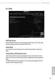
... Flash - DHCP (Auto IP), Auto ASRock Internet Flash downloads and updates the latest UEFI firmware version from our servers for you are having trouble with your PC. Please setup network configuration before using Internet Flash. *For BIOS backup and recovery purpose, it is recommended to plug in your USB storage device and run Instant Flash to update your USB pen drive before using this function. 65 English Please setup network configuration before using UEFI Tech Service. Instant Flash Save UEFI files in your UEFI. 4.7 Tools H310M-G/M.2 UEFI Tech Service Contact ASRock...
... Flash - DHCP (Auto IP), Auto ASRock Internet Flash downloads and updates the latest UEFI firmware version from our servers for you are having trouble with your PC. Please setup network configuration before using Internet Flash. *For BIOS backup and recovery purpose, it is recommended to plug in your USB storage device and run Instant Flash to update your USB pen drive before using this function. 65 English Please setup network configuration before using UEFI Tech Service. Instant Flash Save UEFI files in your UEFI. 4.7 Tools H310M-G/M.2 UEFI Tech Service Contact ASRock...

User Manual
Page 71
UEFI Download Server Select a server to configure internet connection settings for Internet Flash. Internet Setting Enable or disable sound effects in the setup utility. Network Configuration Use this to download the UEFI firmware. 66 English
UEFI Download Server Select a server to configure internet connection settings for Internet Flash. Internet Setting Enable or disable sound effects in the setup utility. Network Configuration Use this to download the UEFI firmware. 66 English

User Manual
Page 73
... Control Mode Select PWM mode or DC mode for Chassis Fan 2. Chassis Fan 2 Step Down Set the value of Chassis Fan 1 Step Down. Over Temperature Protection When Over Temperature Protection is enabled, the system automatically shuts down when the motherboard is overheated. English CHA_FAN2 / W_Pump Switch Select CHA_FAN2 / W_Pump mode. Chassis Fan 1 Step Up Set the value of Chassis Fan 2 Step Up. Case Open Feature Enable or disable Case Open Feature to set 5 CPU temperatures and assign a respective fan speed for...
... Control Mode Select PWM mode or DC mode for Chassis Fan 2. Chassis Fan 2 Step Down Set the value of Chassis Fan 1 Step Down. Over Temperature Protection When Over Temperature Protection is enabled, the system automatically shuts down when the motherboard is overheated. English CHA_FAN2 / W_Pump Switch Select CHA_FAN2 / W_Pump mode. Chassis Fan 1 Step Up Set the value of Chassis Fan 2 Step Up. Case Open Feature Enable or disable Case Open Feature to set 5 CPU temperatures and assign a respective fan speed for...
User Manual
Page 74
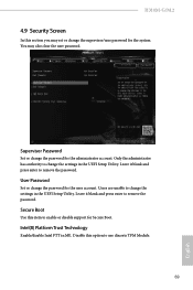
... remove the password. Leave it blank and press enter to change the settings in the UEFI Setup Utility. Disable this option to change the settings in ME. Leave it blank and press enter to enable or disable support for the system. Supervisor Password Set or change the password for the user account. User Password Set or change the supervisor/user password for Secure Boot. You may set or change the password for the administrator account. Secure Boot Use this item to remove the password. H310M-G/M.2 4.9 Security Screen...
... remove the password. Leave it blank and press enter to change the settings in the UEFI Setup Utility. Disable this option to change the settings in ME. Leave it blank and press enter to enable or disable support for the system. Supervisor Password Set or change the password for the user account. User Password Set or change the supervisor/user password for Secure Boot. You may set or change the password for the administrator account. Secure Boot Use this item to remove the password. H310M-G/M.2 4.9 Security Screen...


