

User Manual
Page 4
... 1 1.2 Speciications 2 1.3 Motherboard Layout 6 1.4 I/O Panel 8 Chapter 2 Installation 10 2.1 Installing the CPU 11 2.2 Installing the CPU Fan and Heatsink 14 2.3 Installing Memory Modules (DIMM) 15 2.4 Expansion Slots (PCI Express Slots) 17 2.5 Jumpers Setup 18 2.6 Onboard Headers and Connectors 19 Chapter 3 Software and Utilities Operation 23 3.1 Installing Drivers 23 3.2 A-Tuning 24 3.3 ASRock Live Update & APP Shop 28 3.3.1 UI Overview 28 3.3.2 Apps 29 3.3.3 BIOS & Drivers 32 3.3.4 Setting 33 3.4 Enabling USB Ports for Windows® 7 Installation 34
... 1 1.2 Speciications 2 1.3 Motherboard Layout 6 1.4 I/O Panel 8 Chapter 2 Installation 10 2.1 Installing the CPU 11 2.2 Installing the CPU Fan and Heatsink 14 2.3 Installing Memory Modules (DIMM) 15 2.4 Expansion Slots (PCI Express Slots) 17 2.5 Jumpers Setup 18 2.6 Onboard Headers and Connectors 19 Chapter 3 Software and Utilities Operation 23 3.1 Installing Drivers 23 3.2 A-Tuning 24 3.3 ASRock Live Update & APP Shop 28 3.3.1 UI Overview 28 3.3.2 Apps 29 3.3.3 BIOS & Drivers 32 3.3.4 Setting 33 3.4 Enabling USB Ports for Windows® 7 Installation 34
User Manual
Page 6
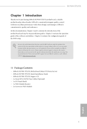
... http://www.asrock.com. 1.1 Package Contents • ASRock H170M-ITX/DL Motherboard (Mini-ITX Form Factor) • ASRock H170M-ITX/DL Quick Installation Guide • ASRock H170M-ITX/DL Support CD • 2 x Serial ATA (SATA) Data Cables (Optional) • 1 x I/O Panel Shield • 1 x WiFi Module Bracket • 2 x Screws for speciic information about the model you for purchasing ASRock H170M-ITX/DL motherboard, a reliable motherboard produced under ASRock's consistently stringent quality control. H170M-ITX/DL Chapter 1 Introduction hank you are using. In case any modiications...
... http://www.asrock.com. 1.1 Package Contents • ASRock H170M-ITX/DL Motherboard (Mini-ITX Form Factor) • ASRock H170M-ITX/DL Quick Installation Guide • ASRock H170M-ITX/DL Support CD • 2 x Serial ATA (SATA) Data Cables (Optional) • 1 x I/O Panel Shield • 1 x WiFi Module Bracket • 2 x Screws for speciic information about the model you for purchasing ASRock H170M-ITX/DL motherboard, a reliable motherboard produced under ASRock's consistently stringent quality control. H170M-ITX/DL Chapter 1 Introduction hank you are using. In case any modiications...
User Manual
Page 8
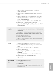
...; Supports DVI-D with max. H170M-ITX/DL • Supports HDMI with max. resolution up to use an HD front panel audio module and enable the multi-channel audio feature through the audio driver. • Premium Blu-ray Audio support • Supports Surge Protection (ASRock Full Spike Protection) • ELNA Audio Caps LAN • 1 x Intel® I219V (Gigabit LAN PHY 10/100/1000 Mb/s) • 1 x Realtek RTL8111H (PCIE x1 Gigabit LAN 10/100/1000 Mb/s) • Supports Wake...
...; Supports DVI-D with max. H170M-ITX/DL • Supports HDMI with max. resolution up to use an HD front panel audio module and enable the multi-channel audio feature through the audio driver. • Premium Blu-ray Audio support • Supports Surge Protection (ASRock Full Spike Protection) • ELNA Audio Caps LAN • 1 x Intel® I219V (Gigabit LAN PHY 10/100/1000 Mb/s) • 1 x Realtek RTL8111H (PCIE x1 Gigabit LAN 10/100/1000 Mb/s) • Supports Wake...

User Manual
Page 9
..., AHCI and Hot Plug • 1 x mSATA Connector (shared with Mini-PCI Express Slot), support RAID (RAID 0, RAID 1, RAID 5, RAID 10, Intel Rapid Storage Technology 14 and Intel Smart Response Technology), NCQ, AHCI and Hot Plug Connector • 1 x TPM Header • 1 x Chassis Intrusion Header • 1 x CPU Fan Connector (4-pin) (Smart Fan Speed Control) • 1 x Chassis Fan Connector (4-pin) (Smart Fan Speed Control) • 1 x 20 pin ATX Power Connector • 1 x 4 pin 12V Power Connector • 1 x Front Panel Audio Connector • 1 x USB 2.0 Header (Supports 2 USB 2.0 ports...
..., AHCI and Hot Plug • 1 x mSATA Connector (shared with Mini-PCI Express Slot), support RAID (RAID 0, RAID 1, RAID 5, RAID 10, Intel Rapid Storage Technology 14 and Intel Smart Response Technology), NCQ, AHCI and Hot Plug Connector • 1 x TPM Header • 1 x Chassis Intrusion Header • 1 x CPU Fan Connector (4-pin) (Smart Fan Speed Control) • 1 x Chassis Fan Connector (4-pin) (Smart Fan Speed Control) • 1 x 20 pin ATX Power Connector • 1 x 4 pin 12V Power Connector • 1 x Front Panel Audio Connector • 1 x USB 2.0 Header (Supports 2 USB 2.0 ports...
User Manual
Page 10
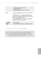
... to page 34 for more detailed instructions. * For the updated Windows® 10 driver, please visit ASRock's website for possible damage caused by overclocking. H170M-ITX/DL OS Certiications • CPU/Chassis Fan multi-speed control • CASE OPEN detection • Voltage monitoring: +12V, +5V, +3.3V, CPU Vcore • Microsot® Windows® 10 64-bit / 8.1 64-bit / 7 32-bit / 7 64bit * To install Windows® 7 OS, a modiied installation disk with xHCI drivers packed into the ISO ile...
... to page 34 for more detailed instructions. * For the updated Windows® 10 driver, please visit ASRock's website for possible damage caused by overclocking. H170M-ITX/DL OS Certiications • CPU/Chassis Fan multi-speed control • CASE OPEN detection • Voltage monitoring: +12V, +5V, +3.3V, CPU Vcore • Microsot® Windows® 10 64-bit / 8.1 64-bit / 7 32-bit / 7 64bit * To install Windows® 7 OS, a modiied installation disk with xHCI drivers packed into the ISO ile...

User Manual
Page 11
1.3 Motherboard Layout 1 2 3 PS2 Keyboard /Mouse Front USB 3.0 DDR4_A1 (64 bit, 288-pin module) DDR4_B1 (64 bit, 288-pin module) USB 2.0 T: USB1 B: USB2 17 DVI1 CHA_FAN1 CPU_FAN1 USB_3_4 4 1 HDMI1 ATXPWR1 USB 3.0 T: USB1 B: USB2 Top: RJ-45 LAN USB 3.0 T: USB3 B: USB4 Top: RJ-45 LAN USB 3.0 T: USB5 B: USB6 HD_AUDIO1 AUDIO CODEC 1 RoHS PCI Express 3.0 Intel H170 MINI_PCIE1 128Mb BIOS H170M-ITX/DL PCIE1 16 15 14 13 12 11 SATA3_3 SATA3_2 SATA3_1 SATA3_0 SPEAKER1...
1.3 Motherboard Layout 1 2 3 PS2 Keyboard /Mouse Front USB 3.0 DDR4_A1 (64 bit, 288-pin module) DDR4_B1 (64 bit, 288-pin module) USB 2.0 T: USB1 B: USB2 17 DVI1 CHA_FAN1 CPU_FAN1 USB_3_4 4 1 HDMI1 ATXPWR1 USB 3.0 T: USB1 B: USB2 Top: RJ-45 LAN USB 3.0 T: USB3 B: USB4 Top: RJ-45 LAN USB 3.0 T: USB5 B: USB6 HD_AUDIO1 AUDIO CODEC 1 RoHS PCI Express 3.0 Intel H170 MINI_PCIE1 128Mb BIOS H170M-ITX/DL PCIE1 16 15 14 13 12 11 SATA3_3 SATA3_2 SATA3_1 SATA3_0 SPEAKER1...

User Manual
Page 22
... of the expansion card and make sure that the power supply is switched of or the power cord is used for PCI Express x16 lane width graphics cards. Before installing an expansion card, please make necessary hardware settings for the card before you start the installation. PCIe slot: PCIE1 (PCIe 3.0 x16 slot) is 1 PCI Express slot and 1 mini-PCI Express slot on the motherboard. H170M-ITX/DL 2.4 Expansion Slots (PCI Express Slots) here is used for WiFi module. * his Mini-PCI Express Slot supports WiFi and mSATA devices. 17 English
... of the expansion card and make sure that the power supply is switched of or the power cord is used for PCI Express x16 lane width graphics cards. Before installing an expansion card, please make necessary hardware settings for the card before you start the installation. PCIe slot: PCIE1 (PCIe 3.0 x16 slot) is 1 PCI Express slot and 1 mini-PCI Express slot on the motherboard. H170M-ITX/DL 2.4 Expansion Slots (PCI Express Slots) here is used for WiFi module. * his Mini-PCI Express Slot supports WiFi and mSATA devices. 17 English

User Manual
Page 23
... chassis intrusion status. When the jumper cap is placed on the pins, the jumper is removed. To clear and reset the system parameters to clear the data in CMOS. If you need to clear the record of the computer and unplug the power cord from the power supply. Please be noted that the password, date, time, and user default proile will be detected. Please adjust the BIOS option "Clear...
... chassis intrusion status. When the jumper cap is placed on the pins, the jumper is removed. To clear and reset the system parameters to clear the data in CMOS. If you need to clear the record of the computer and unplug the power cord from the power supply. Please be noted that the password, date, time, and user default proile will be detected. Please adjust the BIOS option "Clear...

User Manual
Page 24
... wire assignments and the pin assignments are NOT jumpers. PLED (System Power LED): Connect to the reset switch on the chassis front panel. he LED keeps blinking when the system is in S4 sleep state or powered of when the system is in S1/S3 sleep state. English 19 RESET (Reset Switch): Connect to the power status indicator on the chassis front panel. PWRBTN (Power Switch): Connect to the motherboard. When connecting your system using the power switch. H170M-ITX/DL 2.6 Onboard Headers and Connectors Onboard headers...
... wire assignments and the pin assignments are NOT jumpers. PLED (System Power LED): Connect to the reset switch on the chassis front panel. he LED keeps blinking when the system is in S4 sleep state or powered of when the system is in S1/S3 sleep state. English 19 RESET (Reset Switch): Connect to the power status indicator on the chassis front panel. PWRBTN (Power Switch): Connect to the motherboard. When connecting your system using the power switch. H170M-ITX/DL 2.6 Onboard Headers and Connectors Onboard headers...

User Manual
Page 26
...fan cables to the fan connectors and match the black wire to Pin 1-3. ATX Power Connector (20-pin ATXPWR1) (see p.6, No. 5) 10 20 1 11 his motherboard provides a 4-Pin CPU fan (Quiet Fan) connector. H170M-ITX/DL Chassis Speaker Header (4-pin SPEAKER1) (see p.6, No. 11) SPEAKER DUMMY DUMMY +5V 1 Please connect the chassis speaker to this connector. 21 his motherboard provides a 20-pin ATX power connector. Using a 24-pin ATX power supply: English ATX 12V Power Connector (4-pin ATX12V1) (see p.6, No. 17) Please connect an ATX 12V power supply to connect a 3-Pin CPU fan...
...fan cables to the fan connectors and match the black wire to Pin 1-3. ATX Power Connector (20-pin ATXPWR1) (see p.6, No. 5) 10 20 1 11 his motherboard provides a 4-Pin CPU fan (Quiet Fan) connector. H170M-ITX/DL Chassis Speaker Header (4-pin SPEAKER1) (see p.6, No. 11) SPEAKER DUMMY DUMMY +5V 1 Please connect the chassis speaker to this connector. 21 his motherboard provides a 20-pin ATX power connector. Using a 24-pin ATX power supply: English ATX 12V Power Connector (4-pin ATX12V1) (see p.6, No. 17) Please connect an ATX 12V power supply to connect a 3-Pin CPU fan...
User Manual
Page 28
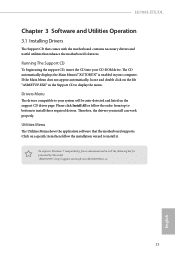
H170M-ITX/DL Chapter 3 Software and Utilities Operation 3.1 Installing Drivers he drivers compatible to your system will be auto-detected and listed on the support CD driver page. Drivers Menu he Support CD that comes with the motherboard contains necessary drivers and useful utilities that the motherboard supports. Click on the ile "ASRSETUP.EXE" in your CD-ROM drive. To improve Windows 7 compatibility, please download and install the following hot ix provided by Microsot. he Utilities Menu shows the application sotware...
H170M-ITX/DL Chapter 3 Software and Utilities Operation 3.1 Installing Drivers he drivers compatible to your system will be auto-detected and listed on the support CD driver page. Drivers Menu he Support CD that comes with the motherboard contains necessary drivers and useful utilities that the motherboard supports. Click on the ile "ASRSETUP.EXE" in your CD-ROM drive. To improve Windows 7 compatibility, please download and install the following hot ix provided by Microsot. he Utilities Menu shows the application sotware...

User Manual
Page 39
... UEFI SETUP UTILITY > Advanced > USB Coniguration, which allows the USB port to function as a PS/2 port, and then you can skip the instructions below to install Windows® 7 OS. Please set PS/S Simulator back to install Windows 7 operating system because the USB ports on their support for the Enhanced Host Controller Interface (EHCI - In order for the USB ports to install Windows® 7 OS. 34 English hen use the new patched Windows® 7 installation USB drive...
... UEFI SETUP UTILITY > Advanced > USB Coniguration, which allows the USB port to function as a PS/2 port, and then you can skip the instructions below to install Windows® 7 OS. Please set PS/S Simulator back to install Windows 7 operating system because the USB ports on their support for the Enhanced Host Controller Interface (EHCI - In order for the USB ports to install Windows® 7 OS. 34 English hen use the new patched Windows® 7 installation USB drive...
User Manual
Page 40
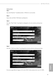
Step 4 Select the "USB Driver Folder" by clicking the red circle as shown as the picture below . If you are using ASRock's Support CD for the USB 3.0 driver, please select your system. Step 2 Extract the tool (Win7 USB Patcher) and launch it. H170M-ITX/DL Instructions Step 1 Insert the Windows® 7 installation disk or USB drive to your CD-ROM. 35 English Step 3 Select the "Win7 Folder" from Step1 by clicking the red circle as shown as the picture below .
Step 4 Select the "USB Driver Folder" by clicking the red circle as shown as the picture below . If you are using ASRock's Support CD for the USB 3.0 driver, please select your system. Step 2 Extract the tool (Win7 USB Patcher) and launch it. H170M-ITX/DL Instructions Step 1 Insert the Windows® 7 installation disk or USB drive to your CD-ROM. 35 English Step 3 Select the "Win7 Folder" from Step1 by clicking the red circle as shown as the picture below .

User Manual
Page 42
... see on . H170M-ITX/DL Chapter 4 UEFI SETUP UTILITY 4.1 Introduction his section explains how to use the UEFI SETUP UTILITY to enter the UEFI SETUP UTILITY ater POST, restart the system by pressing + + , or by pressing the reset button on the system chassis. You may not exactly match what you power on the computer, otherwise, the Power-On-Self-Test (POST) will continue with the following selections: Main For setting system time/date...
... see on . H170M-ITX/DL Chapter 4 UEFI SETUP UTILITY 4.1 Introduction his section explains how to use the UEFI SETUP UTILITY to enter the UEFI SETUP UTILITY ater POST, restart the system by pressing + + , or by pressing the reset button on the system chassis. You may not exactly match what you power on the computer, otherwise, the Power-On-Self-Test (POST) will continue with the following selections: Main For setting system time/date...

User Manual
Page 57
... installed. PCH DMI ASPM Support his option enables/disables the ASPM support for lower power consumption. Onboard LAN Enable or disable the onboard network interface controller. Set to Auto to disable the integrated graphics when an external graphics card is selected, the power will start to keep the integrated graphics enabled at all PCH DMI devices. Restore on AC/Power Loss Select the power state ater a power failure. Select enable to boot up . IGPU Multi-Monitor Select disable to enable onboard HD audio and automatically disable it...
... installed. PCH DMI ASPM Support his option enables/disables the ASPM support for lower power consumption. Onboard LAN Enable or disable the onboard network interface controller. Set to Auto to disable the integrated graphics when an external graphics card is selected, the power will start to keep the integrated graphics enabled at all PCH DMI devices. Restore on AC/Power Loss Select the power state ater a power failure. Select enable to boot up . IGPU Multi-Monitor Select disable to enable onboard HD audio and automatically disable it...
User Manual
Page 64
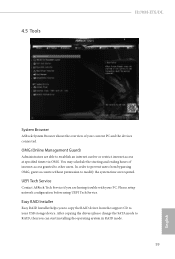
... setup network coniguration before using UEFI Tech Service. In order to prevent users from the support CD to your PC. Easy RAID Installer Easy RAID Installer helps you can start installing the operating system in RAID mode. 59 English Ater copying the drivers please change the SATA mode to RAID, then you to copy the RAID driver from bypassing OMG, guest accounts without permission to modify the system time are required. 4.5 Tools H170M-ITX/DL...
... setup network coniguration before using UEFI Tech Service. In order to prevent users from the support CD to your PC. Easy RAID Installer Easy RAID Installer helps you can start installing the operating system in RAID mode. 59 English Ater copying the drivers please change the SATA mode to RAID, then you to copy the RAID driver from bypassing OMG, guest accounts without permission to modify the system time are required. 4.5 Tools H170M-ITX/DL...

User Manual
Page 65
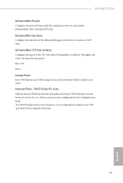
... UEFI that installs the LAN driver to dehumidify the system ater entering S4/S5 state. 60 English Dehumidiier Function If Dehumidiier Function is speciically designed for the Boot Manager. Timeout Seconds Conigure the number of seconds to wait for the dual OS platform/multi-OS platform users to easily customize and manage the boot menu. *Please connect more than one boot devices to use...
... UEFI that installs the LAN driver to dehumidify the system ater entering S4/S5 state. 60 English Dehumidiier Function If Dehumidiier Function is speciically designed for the Boot Manager. Timeout Seconds Conigure the number of seconds to wait for the dual OS platform/multi-OS platform users to easily customize and manage the boot menu. *Please connect more than one boot devices to use...
User Manual
Page 66
... updates the latest UEFI irmware version from our servers for you. Please setup network coniguration before using Internet Flash. *For BIOS backup and recovery purpose, it returns to update your UEFI. Max: 255 Min: 1 Instant Flash Save UEFI iles in your USB storage device and run Instant Flash to S4/S5 state. Internet Flash - Dehumidiier CPU Fan Setting Conigure the speed of time until the computer powers on and enables Dehumidiier ater entering S4/S5 state. H170M-ITX/DL...
... updates the latest UEFI irmware version from our servers for you. Please setup network coniguration before using Internet Flash. *For BIOS backup and recovery purpose, it returns to update your UEFI. Max: 255 Min: 1 Instant Flash Save UEFI iles in your USB storage device and run Instant Flash to S4/S5 state. Internet Flash - Dehumidiier CPU Fan Setting Conigure the speed of time until the computer powers on and enables Dehumidiier ater entering S4/S5 state. H170M-ITX/DL...

User Manual
Page 67
Network Coniguration Use this to download the UEFI irmware. 62 English UEFI Download Server Select a server to conigure internet connection settings for Internet Flash. Internet Setting Enable or disable sound efects in the setup utility.
Network Coniguration Use this to download the UEFI irmware. 62 English UEFI Download Server Select a server to conigure internet connection settings for Internet Flash. Internet Setting Enable or disable sound efects in the setup utility.

User Manual
Page 70
... password. User Password Set or change the password for the user account. Leave it blank and press enter to change the settings in ME. Supervisor Password Set or change the password for the administrator account. Disable this option to remove the password. Intel(R) Platform Trust Technology Enable/disable Intel PTT in the UEFI Setup Utility. Leave it blank and press enter to use discrete TPM Module. 65 English You may set or change the supervisor/user password for Windows 8.1 Secure Boot. H170M-ITX/DL 4.7 Security Screen...
... password. User Password Set or change the password for the user account. Leave it blank and press enter to change the settings in ME. Supervisor Password Set or change the password for the administrator account. Disable this option to remove the password. Intel(R) Platform Trust Technology Enable/disable Intel PTT in the UEFI Setup Utility. Leave it blank and press enter to use discrete TPM Module. 65 English You may set or change the supervisor/user password for Windows 8.1 Secure Boot. H170M-ITX/DL 4.7 Security Screen...


