

User Manual
Page 2
... in this device must accept any kind, either expressed or implied, including but not limited to the contents of this motherboard contains Perchlorate, a toxic substance controlled in advance. With respect to the implied warranties or conditions of merchantability or fitness ...may not cause harmful interference, and (2) this documentation may or may apply, see www.dtsc.ca.gov/hazardouswaste/ perchlorate" ASRock Website: http://www.asrock.com "Perchlorate Material-special handling may not be constructed as a commitment by the California Legislature. CALIFORNIA, USA ONLY The...
... in this device must accept any kind, either expressed or implied, including but not limited to the contents of this motherboard contains Perchlorate, a toxic substance controlled in advance. With respect to the implied warranties or conditions of merchantability or fitness ...may not cause harmful interference, and (2) this documentation may or may apply, see www.dtsc.ca.gov/hazardouswaste/ perchlorate" ASRock Website: http://www.asrock.com "Perchlorate Material-special handling may not be constructed as a commitment by the California Legislature. CALIFORNIA, USA ONLY The...

User Manual
Page 4
... Contents 1 1.2 Specifications 2 1.3 Motherboard Layout 6 1.4 I/O Panel 8 Chapter 2 Installation 10 2.1 Installing the CPU 11 2.2 Installing the CPU Fan and Heatsink 14 2.3 Installing Memory Modules (DIMM) 15 2.4 Expansion Slots (PCI and PCI Express Slots) 17 2.5 Jumpers Setup 18 2.6 Onboard Headers and Connectors 19 Chapter 3 Software and Utilities Operation 23 3.1 Installing Drivers 23 3.2 ASRock Live Update...
... Contents 1 1.2 Specifications 2 1.3 Motherboard Layout 6 1.4 I/O Panel 8 Chapter 2 Installation 10 2.1 Installing the CPU 11 2.2 Installing the CPU Fan and Heatsink 14 2.3 Installing Memory Modules (DIMM) 15 2.4 Expansion Slots (PCI and PCI Express Slots) 17 2.5 Jumpers Setup 18 2.6 Onboard Headers and Connectors 19 Chapter 3 Software and Utilities Operation 23 3.1 Installing Drivers 23 3.2 ASRock Live Update...
User Manual
Page 6
... software and utilities. In this documentation, Chapter 1 and 2 contains the introduction of this documentation will be subject to quality and endurance. ASRock website http://www.asrock.com. 1.1 Package Contents • ASRock H110M-HDVP Motherboard (Micro ATX Form Factor) • ASRock H110M-HDVP Quick Installation Guide • ASRock H110M-HDVP Support CD • 2 x Serial ATA (SATA) Data Cables (Optional) • 1 x I/O Panel Shield 1 English
... software and utilities. In this documentation, Chapter 1 and 2 contains the introduction of this documentation will be subject to quality and endurance. ASRock website http://www.asrock.com. 1.1 Package Contents • ASRock H110M-HDVP Motherboard (Micro ATX Form Factor) • ASRock H110M-HDVP Quick Installation Guide • ASRock H110M-HDVP Support CD • 2 x Serial ATA (SATA) Data Cables (Optional) • 1 x I/O Panel Shield 1 English

User Manual
Page 11
1.3 Motherboard Layout 1 2 3 PS2 Mouse PS2 Keyboard ATX12V1 CPU_FAN1 VGA1 DVI1 DDR4_A1 (64 bit, 288-pin module) DDR4_B1 (64 bit, 288-pin module) ATXPWR1 COM1 HDMI1 4 USB 3.0 T: USB0 B: USB1 USB 2.0 T: USB0 B: USB1 Top: RJ-45 HD_AUDIO1 CHA_FAN1 CMOS Battery H110M-HDVP RoHS CHA_FAN2 Top: LINE IN Center: FRONT Bottom: MIC IN 20 1 PCIE1 5 19 PCI...
1.3 Motherboard Layout 1 2 3 PS2 Mouse PS2 Keyboard ATX12V1 CPU_FAN1 VGA1 DVI1 DDR4_A1 (64 bit, 288-pin module) DDR4_B1 (64 bit, 288-pin module) ATXPWR1 COM1 HDMI1 4 USB 3.0 T: USB0 B: USB1 USB 2.0 T: USB0 B: USB1 Top: RJ-45 HD_AUDIO1 CHA_FAN1 CMOS Battery H110M-HDVP RoHS CHA_FAN2 Top: LINE IN Center: FRONT Bottom: MIC IN 20 1 PCIE1 5 19 PCI...

User Manual
Page 15
... cord before you handle the components. • Hold components by the edges and do not overtighten the screws! Before you install the motherboard, study the configuration of the following precautions before you uninstall any components, place them on a carpet. Failure to the chassis, please ...do not touch the ICs. • Whenever you install motherboard components or change any motherboard settings. • Make sure to use a grounded wrist strap or touch a safety grounded object before installing or removing the...
... cord before you handle the components. • Hold components by the edges and do not overtighten the screws! Before you install the motherboard, study the configuration of the following precautions before you uninstall any components, place them on a carpet. Failure to the chassis, please ...do not touch the ICs. • Whenever you install motherboard components or change any motherboard settings. • Make sure to use a grounded wrist strap or touch a safety grounded object before installing or removing the...

User Manual
Page 18
H110M-HDVP Please save and replace the cover if the processor is removed. The cover must be placed if you wish to return the motherboard for after service. 13 English
H110M-HDVP Please save and replace the cover if the processor is removed. The cover must be placed if you wish to return the motherboard for after service. 13 English

User Manual
Page 20
H110M-HDVP 2.3 Installing Memory Modules (DIMM) This motherboard provides two 288-pin DDR4 (Double Data Rate 4) DIMM slots, and supports Dual Channel Memory Technology. 1. It is not allowed to install identical (the same brand, speed, size and chip-type) DDR4 DIMM pairs. 2. otherwise, this motherboard and DIMM may be ...only one correct orientation. The DIMM only fits in one memory module installed. 3. It will cause permanent damage to the motherboard and the DIMM if you always need to install a DDR, DDR2 or DDR3 memory module into the slot at incorrect orientation. 15 ...
H110M-HDVP 2.3 Installing Memory Modules (DIMM) This motherboard provides two 288-pin DDR4 (Double Data Rate 4) DIMM slots, and supports Dual Channel Memory Technology. 1. It is not allowed to install identical (the same brand, speed, size and chip-type) DDR4 DIMM pairs. 2. otherwise, this motherboard and DIMM may be ...only one correct orientation. The DIMM only fits in one memory module installed. 3. It will cause permanent damage to the motherboard and the DIMM if you always need to install a DDR, DDR2 or DDR3 memory module into the slot at incorrect orientation. 15 ...
User Manual
Page 22
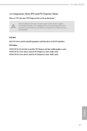
... for PCI Express x16 lane width graphics cards. Please read the documentation of the expansion card and make sure that have 32-bit PCI interface. H110M-HDVP 2.4 Expansion Slots (PCI and PCI Express Slots) There is unplugged. PCIe slots: PCIE1 (PCIe 3.0 x16 slot) is used for the card before you ... to install expansion cards that the power supply is switched off or the power cord is 1 PCI slot and 3 PCI Express slots on the motherboard. PCI slot: The PCI1 slot is used for PCI Express x1 lane width cards. 17 English Before installing an expansion card, please make necessary...
... for PCI Express x16 lane width graphics cards. Please read the documentation of the expansion card and make sure that have 32-bit PCI interface. H110M-HDVP 2.4 Expansion Slots (PCI and PCI Express Slots) There is unplugged. PCIe slots: PCIE1 (PCIe 3.0 x16 slot) is used for the card before you ... to install expansion cards that the power supply is switched off or the power cord is 1 PCI slot and 3 PCI Express slots on the motherboard. PCI slot: The PCI1 slot is used for PCI Express x1 lane width cards. 17 English Before installing an expansion card, please make necessary...

User Manual
Page 24
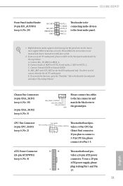
... caps over the headers and connectors will cause permanent damage to the pin assignments below. The LED is on the chassis front panel. English 19 H110M-HDVP 2.6 Onboard Headers and Connectors Onboard headers and connectors are matched correctly. System Panel Header (9-pin PANEL1) (see p.6, No. 11) PLED+ PLEDPWRBTN# GND 1 GND RESET# GND... NOT jumpers. When connecting your system using the power switch. The LED is off your chassis front panel module to this header according to the motherboard. Placing jumper caps over these headers and connectors.
... caps over the headers and connectors will cause permanent damage to the pin assignments below. The LED is on the chassis front panel. English 19 H110M-HDVP 2.6 Onboard Headers and Connectors Onboard headers and connectors are matched correctly. System Panel Header (9-pin PANEL1) (see p.6, No. 11) PLED+ PLEDPWRBTN# GND 1 GND RESET# GND... NOT jumpers. When connecting your system using the power switch. The LED is off your chassis front panel module to this header according to the motherboard. Placing jumper caps over these headers and connectors.

User Manual
Page 25
... IntA_P_SSTXIntA_P_SSTX+ GND IntA_P_DIntA_P_D+ ID Besides two USB 3.0 ports on the I/O panel, there is shared with up to this motherboard. English 20 Each USB 2.0 header can support two ports. * USB3_2_3 is one header on this motherboard. Each USB 3.0 header can support two ports. USB_PWR PP+ GND DUMMY 1 GND P+ PUSB_PWR There are two headers...
... IntA_P_SSTXIntA_P_SSTX+ GND IntA_P_DIntA_P_D+ ID Besides two USB 3.0 ports on the I/O panel, there is shared with up to this motherboard. English 20 Each USB 2.0 header can support two ports. * USB3_2_3 is one header on this motherboard. Each USB 3.0 header can support two ports. USB_PWR PP+ GND DUMMY 1 GND P+ PUSB_PWR There are two headers...
User Manual
Page 26
...Audio_L (LIN) to Ground (GND). Connect Ground (GND) to OUT2_L. ATX Power Connector (24-pin ATXPWR1) (see p.6, No. 2) FAN_SPEED This motherboard pro- Connect Mic_IN (MIC) to the "FrontMic" Tab in our manual and chassis manual to function correctly. B. To activate the front mic, go...(4-pin CPU_FAN1) (see p.6, No. 4) 12 24 1 13 This motherboard provides a 24-pin ATX power connector. E. If you plan to connect a 3-Pin CPU fan, please connect it to Pin 1-3. You don't need to the ground pin. H110M-HDVP Front Panel Audio Header (9-pin HD_AUDIO1) (see p.6, No. 20) ...
...Audio_L (LIN) to Ground (GND). Connect Ground (GND) to OUT2_L. ATX Power Connector (24-pin ATXPWR1) (see p.6, No. 2) FAN_SPEED This motherboard pro- Connect Mic_IN (MIC) to the "FrontMic" Tab in our manual and chassis manual to function correctly. B. To activate the front mic, go...(4-pin CPU_FAN1) (see p.6, No. 4) 12 24 1 13 This motherboard provides a 24-pin ATX power connector. E. If you plan to connect a 3-Pin CPU fan, please connect it to Pin 1-3. You don't need to the ground pin. H110M-HDVP Front Panel Audio Header (9-pin HD_AUDIO1) (see p.6, No. 20) ...

User Manual
Page 27
... cable that allows convenient connection of printer devices. ATX 12V Power Connector (4-pin ATX12V1) (see p.6, No. 1) Serial Port Header (9-pin COM2) (see p.6, No. 18) This motherboard provides an 4-pin ATX 12V power connector. RRXD1 DDTR#1 DDSR#1 CCTS#1 1 RRI#1 RRTS#1 GND TTXD1 DDCD#1 This COM2 header supports a serial port module.
... cable that allows convenient connection of printer devices. ATX 12V Power Connector (4-pin ATX12V1) (see p.6, No. 1) Serial Port Header (9-pin COM2) (see p.6, No. 18) This motherboard provides an 4-pin ATX 12V power connector. RRXD1 DDTR#1 DDSR#1 CCTS#1 1 RRI#1 RRTS#1 GND TTXD1 DDCD#1 This COM2 header supports a serial port module.
User Manual
Page 28
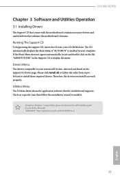
...ROM drive. Therefore, the drivers you install can work properly. Utilities Menu The Utilities Menu shows the application software that enhance the motherboard's features. To improve Windows 7 compatibility, please download and install the following hot fix provided by Microsoft. "KB2720599": http://support....page. Running The Support CD To begin using the support CD, insert the CD into your computer. H110M-HDVP Chapter 3 Software and Utilities Operation 3.1 Installing Drivers The Support CD that comes with the motherboard contains necessary drivers and useful utilities that the...
...ROM drive. Therefore, the drivers you install can work properly. Utilities Menu The Utilities Menu shows the application software that enhance the motherboard's features. To improve Windows 7 compatibility, please download and install the following hot fix provided by Microsoft. "KB2720599": http://support....page. Running The Support CD To begin using the support CD, insert the CD into your computer. H110M-HDVP Chapter 3 Software and Utilities Operation 3.1 Installing Drivers The Support CD that comes with the motherboard contains necessary drivers and useful utilities that the...

User Manual
Page 29
...users to perform job-related tasks. Double-click utility. Click on your desktop to access ASRock Live Update & APP Shop *You need to be connected to the Internet to download apps from the ASRock Live Update & APP Shop. 3.2.1 UI Overview Category Panel Hot News Information Panel Category...news and know more . You can optimize your system and keep your ASRock computer. 3.2 ASRock Live Update & APP Shop The ASRock Live Update & APP Shop is an online store for purchasing and downloading software applications for your motherboard up to date simply with a few clicks. Hot News: The ...
...users to perform job-related tasks. Double-click utility. Click on your desktop to access ASRock Live Update & APP Shop *You need to be connected to the Internet to download apps from the ASRock Live Update & APP Shop. 3.2.1 UI Overview Category Panel Hot News Information Panel Category...news and know more . You can optimize your system and keep your ASRock computer. 3.2 ASRock Live Update & APP Shop The ASRock Live Update & APP Shop is an online store for purchasing and downloading software applications for your motherboard up to date simply with a few clicks. Hot News: The ...

User Manual
Page 35
...Controller Interface (EHCI - Requirements • A Windows® 7 installation disk or USB drive • USB 3.0 drivers (included in the ASRock Support CD or website) • A Windows® PC • Win7 USB Patcher (included in UEFI SETUP UTILITY > Advanced > USB...7 operating system because the USB ports on your computer, please enable the "PS/2 Simulator" option in the ASRock Support CD or website) Scenarios You have an ODD and PS/2 ports: If there is an optical disc drive... for Windows® 7 Installation Intel® Braswell and Skylake has removed their motherboard won't work.
...Controller Interface (EHCI - Requirements • A Windows® 7 installation disk or USB drive • USB 3.0 drivers (included in the ASRock Support CD or website) • A Windows® PC • Win7 USB Patcher (included in UEFI SETUP UTILITY > Advanced > USB...7 operating system because the USB ports on your computer, please enable the "PS/2 Simulator" option in the ASRock Support CD or website) Scenarios You have an ODD and PS/2 ports: If there is an optical disc drive... for Windows® 7 Installation Intel® Braswell and Skylake has removed their motherboard won't work.

User Manual
Page 44
..., the motherboard will be set. Primary Timing CAS# Latency (tCL) The time between sending a column address to the memory and the beginning of the integrated GPU. GT Frequency Configure the frequency of the data in response. 39 English DRAM Reference Clock Select Auto for overclocking will be lowered immediately. H110M-HDVP Long Duration...
..., the motherboard will be set. Primary Timing CAS# Latency (tCL) The time between sending a column address to the memory and the beginning of the integrated GPU. GT Frequency Configure the frequency of the data in response. 39 English DRAM Reference Clock Select Auto for overclocking will be lowered immediately. H110M-HDVP Long Duration...

User Manual
Page 66
... to set 5 CPU temperatures and assign a respective fan speed for each temperature. 61 English Chassis Fan 1 Temp Source Select a fan temperature source for each temperature. H110M-HDVP 4.8 Hardware Health Event Monitoring Screen This section allows you to set 5 CPU temperatures and assign a respective fan speed for each temperature. Fan-Tastic Tuning Select... a fan mode for CPU Fan 1, or choose Customize to monitor the status of the hardware on your system, including the parameters of the CPU temperature, motherboard temperature, fan speed and voltage.
... to set 5 CPU temperatures and assign a respective fan speed for each temperature. 61 English Chassis Fan 1 Temp Source Select a fan temperature source for each temperature. H110M-HDVP 4.8 Hardware Health Event Monitoring Screen This section allows you to set 5 CPU temperatures and assign a respective fan speed for each temperature. Fan-Tastic Tuning Select... a fan mode for CPU Fan 1, or choose Customize to monitor the status of the hardware on your system, including the parameters of the CPU temperature, motherboard temperature, fan speed and voltage.

User Manual
Page 67
Case Open Feature Enable or disable Case Open Feature to detect whether the chassis cover has been removed. 62 English Over Temperature Protection When Over Temperature Protection is enabled, the system automatically shuts down when the motherboard is overheated. Chassis Fan 2 Temp Source Select a fan temperature source for Chassis Fan 2.
Case Open Feature Enable or disable Case Open Feature to detect whether the chassis cover has been removed. 62 English Over Temperature Protection When Over Temperature Protection is enabled, the system automatically shuts down when the motherboard is overheated. Chassis Fan 2 Temp Source Select a fan temperature source for Chassis Fan 2.


