

User Manual
Page 4
... Specifications 2 1.3 Motherboard Layout 6 1.4 I/O Panel 8 Chapter 2 Installation 10 2.1 Installing the CPU 11 2.2 Installing the CPU Fan and Heatsink 14 2.3 Installing Memory Modules (DIMM) 15 2.4 Expansion Slots (PCI and PCI Express Slots) 17 2.5 Jumpers Setup 18 2.6 Onboard Headers and Connectors 19 Chapter 3 Software and Utilities Operation 23 3.1 Installing Drivers 23 3.2 ASRock Live Update & APP Shop 24 3.2.1 UI Overview 24 3.2.2 Apps 25 3.2.3 BIOS & Drivers 28 3.2.4 Setting 29 3.3 Enabling USB Ports for Windows® 7 Installation 30 Chapter 4 UEFI...
... Specifications 2 1.3 Motherboard Layout 6 1.4 I/O Panel 8 Chapter 2 Installation 10 2.1 Installing the CPU 11 2.2 Installing the CPU Fan and Heatsink 14 2.3 Installing Memory Modules (DIMM) 15 2.4 Expansion Slots (PCI and PCI Express Slots) 17 2.5 Jumpers Setup 18 2.6 Onboard Headers and Connectors 19 Chapter 3 Software and Utilities Operation 23 3.1 Installing Drivers 23 3.2 ASRock Live Update & APP Shop 24 3.2.1 UI Overview 24 3.2.2 Apps 25 3.2.3 BIOS & Drivers 28 3.2.4 Setting 29 3.3 Enabling USB Ports for Windows® 7 Installation 30 Chapter 4 UEFI...
User Manual
Page 6
... software and utilities. In case any modifications of the BIOS setup. Chapter 4 contains the configuration guide of this documentation occur, the updated version will be available on ASRock's website as well. If you are using. ASRock website http://www.asrock.com. 1.1 Package Contents • ASRock H110M-HDVP Motherboard (Micro ATX Form Factor) • ASRock H110M-HDVP Quick Installation Guide • ASRock H110M-HDVP Support CD • 2 x Serial ATA (SATA) Data Cables (Optional) • 1 x I/O Panel Shield 1 English H110M-HDVP Chapter 1 Introduction Thank you for specific...
... software and utilities. In case any modifications of the BIOS setup. Chapter 4 contains the configuration guide of this documentation occur, the updated version will be available on ASRock's website as well. If you are using. ASRock website http://www.asrock.com. 1.1 Package Contents • ASRock H110M-HDVP Motherboard (Micro ATX Form Factor) • ASRock H110M-HDVP Quick Installation Guide • ASRock H110M-HDVP Support CD • 2 x Serial ATA (SATA) Data Cables (Optional) • 1 x I/O Panel Shield 1 English H110M-HDVP Chapter 1 Introduction Thank you for specific...
User Manual
Page 8
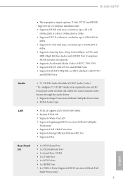
...; Realtek RTL8111E • Supports Wake-On-LAN • Supports Lightning/ESD Protection (ASRock Full Spike Protection) • Supports LAN Cable Detection • Supports Energy Efficient Ethernet 802.3az • Supports PXE Rear Panel I/O • 1 x PS/2 Mouse Port • 1 x PS/2 Keyboard Port • 1 x Serial Port: COM1 • 1 x D-Sub Port • 1 x DVI-D Port • 1 x HDMI Port • 4 x USB 2.0 Ports (Supports ESD Protection (ASRock Full Spike Protection)) 3 English H110M-HDVP • Three graphics output options: D-Sub, DVI-D and HDMI * Supports up to 4K...
...; Realtek RTL8111E • Supports Wake-On-LAN • Supports Lightning/ESD Protection (ASRock Full Spike Protection) • Supports LAN Cable Detection • Supports Energy Efficient Ethernet 802.3az • Supports PXE Rear Panel I/O • 1 x PS/2 Mouse Port • 1 x PS/2 Keyboard Port • 1 x Serial Port: COM1 • 1 x D-Sub Port • 1 x DVI-D Port • 1 x HDMI Port • 4 x USB 2.0 Ports (Supports ESD Protection (ASRock Full Spike Protection)) 3 English H110M-HDVP • Three graphics output options: D-Sub, DVI-D and HDMI * Supports up to 4K...

User Manual
Page 9
...8226; AMI UEFI Legal BIOS with USB_6_7. • 2 x USB 3.0 Ports (Supports ESD Protection (ASRock Full Spike Protection)) • 1 x RJ-45 LAN Port with LED (ACT/LINK LED and SPEED LED) • HD Audio Jacks: Line in / Front Speaker / Microphone Storage • 4 x SATA3 6.0 Gb/s Connectors, support NCQ, AHCI and Hot Plug Connector • 1 x Print Port Header • 1 x COM Port Header • 1 x TPM Header • 1 x Chassis Intrusion and Speaker Header • 1 x CPU Fan Connector (4-pin) • 2 x Chassis Fan Connectors (4-pin) * The CPU Fan Connector supports the CPU fan of...
...8226; AMI UEFI Legal BIOS with USB_6_7. • 2 x USB 3.0 Ports (Supports ESD Protection (ASRock Full Spike Protection)) • 1 x RJ-45 LAN Port with LED (ACT/LINK LED and SPEED LED) • HD Audio Jacks: Line in / Front Speaker / Microphone Storage • 4 x SATA3 6.0 Gb/s Connectors, support NCQ, AHCI and Hot Plug Connector • 1 x Print Port Header • 1 x COM Port Header • 1 x TPM Header • 1 x Chassis Intrusion and Speaker Header • 1 x CPU Fan Connector (4-pin) • 2 x Chassis Fan Connectors (4-pin) * The CPU Fan Connector supports the CPU fan of...
User Manual
Page 10
bit * To install Windows® 7 OS, a modified installation disk with xHCI drivers packed into the ISO file is a certain risk involved with overclocking, including adjusting the setting in the BIOS, applying Untied Overclocking Technology, or using third-party overclocking tools. Please refer to the components and devices of your system. We are not responsible for details: http://www.asrock.com Certifications • FCC, CE, WHQL • ErP...
bit * To install Windows® 7 OS, a modified installation disk with xHCI drivers packed into the ISO file is a certain risk involved with overclocking, including adjusting the setting in the BIOS, applying Untied Overclocking Technology, or using third-party overclocking tools. Please refer to the components and devices of your system. We are not responsible for details: http://www.asrock.com Certifications • FCC, CE, WHQL • ErP...

User Manual
Page 12
...) 2 CPU Fan Connector (CPU_FAN1) 3 2 x 288-pin DDR4 DIMM Slots (DDR4_A1, DDR4_B1) 4 ATX Power Connector (ATXPWR1) 5 Chassis Fan Connector (CHA_FAN2) 6 SATA3 Connector (SATA3_0) 7 SATA3 Connector (SATA3_1) 8 SATA3 Connector (SATA3_2) 9 SATA3 Connector (SATA3_3) 10 Clear CMOS Jumper (CLRMOS1) 11 System Panel Header (PANEL1) 12 USB 3.0 Header (USB3_2_3) 13 USB 2.0 Header (USB_6_7) 14 USB 2.0 Header (USB_4_5) 15 Chassis Intrusion and Speaker Header (SPK_CI1) 16 Print Port Header (LPT1) 17 TPM Header (TPMS1) 18 COM Port Header (COM2) 19 Chassis Fan Connector (CHA_FAN1) 20 Front Panel Audio Header...
...) 2 CPU Fan Connector (CPU_FAN1) 3 2 x 288-pin DDR4 DIMM Slots (DDR4_A1, DDR4_B1) 4 ATX Power Connector (ATXPWR1) 5 Chassis Fan Connector (CHA_FAN2) 6 SATA3 Connector (SATA3_0) 7 SATA3 Connector (SATA3_1) 8 SATA3 Connector (SATA3_2) 9 SATA3 Connector (SATA3_3) 10 Clear CMOS Jumper (CLRMOS1) 11 System Panel Header (PANEL1) 12 USB 3.0 Header (USB3_2_3) 13 USB 2.0 Header (USB_6_7) 14 USB 2.0 Header (USB_4_5) 15 Chassis Intrusion and Speaker Header (SPK_CI1) 16 Print Port Header (LPT1) 17 TPM Header (TPMS1) 18 COM Port Header (COM2) 19 Chassis Fan Connector (CHA_FAN1) 20 Front Panel Audio Header...
User Manual
Page 22
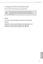
... 32-bit PCI interface. H110M-HDVP 2.4 Expansion Slots (PCI and PCI Express Slots) There is unplugged. Before installing an expansion card, please make necessary hardware settings for PCI Express x16 lane width graphics cards. PCI slot: The PCI1 slot is used for PCI Express x1 lane width cards. 17 English PCIe slots: PCIE1 (PCIe 3.0 x16 slot) is used for the card before you start the installation. PCIE3 (PCIe 2.0 x1 slot) is used for PCI Express x1 lane width cards. PCIE2 (PCIe 2.0 x1 slot) is used to install expansion cards that the power supply is switched...
... 32-bit PCI interface. H110M-HDVP 2.4 Expansion Slots (PCI and PCI Express Slots) There is unplugged. Before installing an expansion card, please make necessary hardware settings for PCI Express x16 lane width graphics cards. PCI slot: The PCI1 slot is used for PCI Express x1 lane width cards. 17 English PCIe slots: PCIE1 (PCIe 3.0 x16 slot) is used for the card before you start the installation. PCIE3 (PCIe 2.0 x1 slot) is used for PCI Express x1 lane width cards. PCIE2 (PCIe 2.0 x1 slot) is used to install expansion cards that the power supply is switched...

User Manual
Page 23
... power cord from the power supply. Clear CMOS Jumper (CLRMOS1) (see p.6, No. 10) Default Clear CMOS CLRMOS1 allows you update the BIOS. However, please do the clear-CMOS action. English 18 If no jumper cap is placed on the pins, the jumper is "Short". The illustration shows a 3-pin jumper whose pin1 and pin2 are setup. Please adjust the BIOS option "Clear Status" to short pin2 and pin3 on CLRMOS1 for 15 seconds, use a jumper cap to clear...
... power cord from the power supply. Clear CMOS Jumper (CLRMOS1) (see p.6, No. 10) Default Clear CMOS CLRMOS1 allows you update the BIOS. However, please do the clear-CMOS action. English 18 If no jumper cap is placed on the pins, the jumper is "Short". The illustration shows a 3-pin jumper whose pin1 and pin2 are setup. Please adjust the BIOS option "Clear Status" to short pin2 and pin3 on CLRMOS1 for 15 seconds, use a jumper cap to clear...

User Manual
Page 24
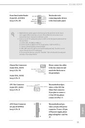
... sleep state or powered off (S5). When connecting your system using the power switch. The LED keeps blinking when the system is operating. HDLED (Hard Drive Activity LED): Connect to the pin assignments below. H110M-HDVP 2.6 Onboard Headers and Connectors Onboard headers and connectors are matched correctly. System Panel Header (9-pin PANEL1) (see p.6, No. 11) PLED+ PLEDPWRBTN# GND 1 GND RESET# GND HDLEDHDLED+ Connect the power switch, reset switch and system status indicator on the chassis to this header, make sure the wire...
... sleep state or powered off (S5). When connecting your system using the power switch. The LED keeps blinking when the system is operating. HDLED (Hard Drive Activity LED): Connect to the pin assignments below. H110M-HDVP 2.6 Onboard Headers and Connectors Onboard headers and connectors are matched correctly. System Panel Header (9-pin PANEL1) (see p.6, No. 11) PLED+ PLEDPWRBTN# GND 1 GND RESET# GND HDLEDHDLED+ Connect the power switch, reset switch and system status indicator on the chassis to this header, make sure the wire...
User Manual
Page 26
... don't need to Pin 1-3. ATX Power Connector (24-pin ATXPWR1) (see p.6, No. 2) FAN_SPEED This motherboard pro- D. To activate the front mic, go to install your system. 2. If you use a 20-pin ATX power supply, please plug it to connect them for the HD audio panel only. E. FAN_VOLTAGE_CONTROL GND FAN_SPEED_CONTROL vides a 4-Pin CPU fan (Quiet Fan) connector. Please follow the instructions in our manual and chassis manual to the "FrontMic" Tab in the Realtek Control panel and adjust "Recording...
... don't need to Pin 1-3. ATX Power Connector (24-pin ATXPWR1) (see p.6, No. 2) FAN_SPEED This motherboard pro- D. To activate the front mic, go to install your system. 2. If you use a 20-pin ATX power supply, please plug it to connect them for the HD audio panel only. E. FAN_VOLTAGE_CONTROL GND FAN_SPEED_CONTROL vides a 4-Pin CPU fan (Quiet Fan) connector. Please follow the instructions in our manual and chassis manual to the "FrontMic" Tab in the Realtek Control panel and adjust "Recording...
User Manual
Page 28
H110M-HDVP Chapter 3 Software and Utilities Operation 3.1 Installing Drivers The Support CD that comes with the motherboard contains necessary drivers and useful utilities that the motherboard supports. Drivers Menu The drivers compatible to display the menu. Therefore, the drivers you install can work properly. To improve Windows 7 compatibility, please download and install the following hot fix provided by Microsoft. If the Main Menu does not appear automatically, locate and double click on the file "ASRSETUP.EXE" in your computer. Utilities Menu The Utilities Menu shows...
H110M-HDVP Chapter 3 Software and Utilities Operation 3.1 Installing Drivers The Support CD that comes with the motherboard contains necessary drivers and useful utilities that the motherboard supports. Drivers Menu The drivers compatible to display the menu. Therefore, the drivers you install can work properly. To improve Windows 7 compatibility, please download and install the following hot fix provided by Microsoft. If the Main Menu does not appear automatically, locate and double click on the file "ASRSETUP.EXE" in your computer. Utilities Menu The Utilities Menu shows...

User Manual
Page 35
... in UEFI SETUP UTILITY > Advanced > USB Configuration, which allows the USB port to function as a PS/2 port, and then you can install the Windows® 7 OS. 3.3 Enabling USB Ports for Windows® 7 Installation Intel® Braswell and Skylake has removed their motherboard won't work. Then use the new patched Windows® 7 installation USB drive to disabled after the installation. You only have an optical disc drive, please find it difficult to install Windows 7 operating system because the USB ports on...
... in UEFI SETUP UTILITY > Advanced > USB Configuration, which allows the USB port to function as a PS/2 port, and then you can install the Windows® 7 OS. 3.3 Enabling USB Ports for Windows® 7 Installation Intel® Braswell and Skylake has removed their motherboard won't work. Then use the new patched Windows® 7 installation USB drive to disabled after the installation. You only have an optical disc drive, please find it difficult to install Windows 7 operating system because the USB ports on...
User Manual
Page 36
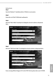
Step 3 Select the "Win7 Folder" from Step1 by clicking the red circle as shown as the picture below . If you are using ASRock's Support CD for the USB 3.0 driver, please select your system. Step 4 Select the "USB Driver Folder" by clicking the red circle as shown as the picture below . H110M-HDVP Instructions Step 1 Insert the Windows® 7 installation disk or USB drive to your CD-ROM. 31 English Step 2 Extract the tool (Win7 USB Patcher) and launch it.
Step 3 Select the "Win7 Folder" from Step1 by clicking the red circle as shown as the picture below . If you are using ASRock's Support CD for the USB 3.0 driver, please select your system. Step 4 Select the "USB Driver Folder" by clicking the red circle as shown as the picture below . H110M-HDVP Instructions Step 1 Insert the Windows® 7 installation disk or USB drive to your CD-ROM. 31 English Step 2 Extract the tool (Win7 USB Patcher) and launch it.

User Manual
Page 55
... power will start to boot up . Onboard LAN Enable or disable the onboard network interface controller. Onboard HD Audio Enable/disable onboard HD audio. Deep Sleep Configure deep sleep mode for the onboard digital outputs. Select enable to the integrated graphics processor when the system boots up when the power recovers. 50 English If [Power Off] is selected, the system will remain off when the power recovers. PCH DMI ASPM Support This option enables/disables the ASPM support for all times. Front Panel Enable/disable front panel...
... power will start to boot up . Onboard LAN Enable or disable the onboard network interface controller. Onboard HD Audio Enable/disable onboard HD audio. Deep Sleep Configure deep sleep mode for the onboard digital outputs. Select enable to the integrated graphics processor when the system boots up when the power recovers. 50 English If [Power Off] is selected, the system will remain off when the power recovers. PCH DMI ASPM Support This option enables/disables the ASPM support for all times. Front Panel Enable/disable front panel...

User Manual
Page 59
... be waked up by a PCI device and enable wake on LAN. USB Keyboard/Remote Power On Allow the system to select auto for better performance. PCI Devices Power On Allow the system to let it be waked up by a PS/2 Keyboard. Set it to By OS to be waked up by an USB keyboard or remote controller. 54 English ACPI HEPT Table Enable the High Precision Event Timer for ACPI S3 power saving. PS/2 Keyboard Power On...
... be waked up by a PCI device and enable wake on LAN. USB Keyboard/Remote Power On Allow the system to select auto for better performance. PCI Devices Power On Allow the system to let it be waked up by a PS/2 Keyboard. Set it to By OS to be waked up by an USB keyboard or remote controller. 54 English ACPI HEPT Table Enable the High Precision Event Timer for ACPI S3 power saving. PS/2 Keyboard Power On...

User Manual
Page 61
This should be enabled for the complete USB keyboard legacy support for USB 2.0 devices. If you install Windows 7. 56 English PS/2 Simulator Enable PS/2 Simulator. Select UEFI Setup Only to disable legacy USB support. 4.6.6 USB Configuration Legacy USB Support Enable or disable Legacy OS Support for non-USB aware OSes. *Enable this option if you encounter USB compatibility issues it is recommended to support USB devices under the UEFI setup and Windows/Linux operating systems only.
This should be enabled for the complete USB keyboard legacy support for USB 2.0 devices. If you install Windows 7. 56 English PS/2 Simulator Enable PS/2 Simulator. Select UEFI Setup Only to disable legacy USB support. 4.6.6 USB Configuration Legacy USB Support Enable or disable Legacy OS Support for non-USB aware OSes. *Enable this option if you encounter USB compatibility issues it is recommended to support USB devices under the UEFI setup and Windows/Linux operating systems only.
User Manual
Page 63
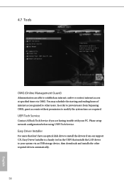
Easy Driver Installer For users that installs the LAN driver to establish an internet curfew or restrict internet access at specified times via an USB storage device, then downloads and installs the other users. UEFI Tech Service Contact ASRock Tech Service if you are required. 4.7 Tools OMG (Online Management Guard) Administrators are able to your PC. Please setup network configuration before using UEFI Tech Service. In order to prevent users from our support CD, Easy Driver Installer is...
Easy Driver Installer For users that installs the LAN driver to establish an internet curfew or restrict internet access at specified times via an USB storage device, then downloads and installs the other users. UEFI Tech Service Contact ASRock Tech Service if you are required. 4.7 Tools OMG (Online Management Guard) Administrators are able to your PC. Please setup network configuration before using UEFI Tech Service. In order to prevent users from our support CD, Easy Driver Installer is...
User Manual
Page 64
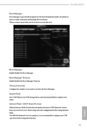
.... Internet Flash - DHCP (Auto IP), Auto ASRock Internet Flash downloads and updates the latest UEFI firmware version from our servers for the Boot Manager. Please setup network configuration before using this tool. Boot Manager Enable/disable the Boot Manager. H110M-HDVP Boot Manager Boot Manager is recommended to plug in your USB storage device and run Instant Flash to update your USB pen drive before using Internet Flash. *For BIOS backup and recovery purpose, it is specifically designed for the dual OS platform/multi-OS platform users to...
.... Internet Flash - DHCP (Auto IP), Auto ASRock Internet Flash downloads and updates the latest UEFI firmware version from our servers for the Boot Manager. Please setup network configuration before using this tool. Boot Manager Enable/disable the Boot Manager. H110M-HDVP Boot Manager Boot Manager is recommended to plug in your USB storage device and run Instant Flash to update your USB pen drive before using Internet Flash. *For BIOS backup and recovery purpose, it is specifically designed for the dual OS platform/multi-OS platform users to...

User Manual
Page 65
UEFI Download Server Select a server to configure internet connection settings for Internet Flash. Internet Setting Enable or disable sound effects in the setup utility. Network Configuration Use this to download the UEFI firmware. 60 English
UEFI Download Server Select a server to configure internet connection settings for Internet Flash. Internet Setting Enable or disable sound effects in the setup utility. Network Configuration Use this to download the UEFI firmware. 60 English

User Manual
Page 68
H110M-HDVP 4.9 Security Screen In this item to enable or disable support for Windows 8.1 Secure Boot. You may set or change the supervisor/user password for the system. Secure Boot Use this section you may also clear the user password. Only the administrator has authority to change the settings in the UEFI Setup Utility. Intel(R) Platform Trust Technology Enable/disable Intel PTT in the UEFI Setup Utility. Disable this option to remove the password. User Password Set or change the password for the user account. Supervisor Password Set or change the password for...
H110M-HDVP 4.9 Security Screen In this item to enable or disable support for Windows 8.1 Secure Boot. You may set or change the supervisor/user password for the system. Secure Boot Use this section you may also clear the user password. Only the administrator has authority to change the settings in the UEFI Setup Utility. Intel(R) Platform Trust Technology Enable/disable Intel PTT in the UEFI Setup Utility. Disable this option to remove the password. User Password Set or change the password for the user account. Supervisor Password Set or change the password for...


