
User Manual
Page 4
... 2 1.3 Motherboard Layout 6 1.4 I/O Panel 10 Chapter 2 Installation 14 2.1 Installing the CPU 15 2.2 Installing the CPU Fan and Heatsink 18 2.3 Installing Memory Modules (DIMM) 19 2.4 Expansion Slots (PCI Express Slots) 21 2.5 Onboard Headers and Connectors 22 Chapter 3 Software and Utilities Operation 26 3.1 Installing Drivers 26 3.2 ASRock Live Update & APP Shop 27 3.2.1 UI Overview 27 3.2.2 Apps...
... 2 1.3 Motherboard Layout 6 1.4 I/O Panel 10 Chapter 2 Installation 14 2.1 Installing the CPU 15 2.2 Installing the CPU Fan and Heatsink 18 2.3 Installing Memory Modules (DIMM) 19 2.4 Expansion Slots (PCI Express Slots) 21 2.5 Onboard Headers and Connectors 22 Chapter 3 Software and Utilities Operation 26 3.1 Installing Drivers 26 3.2 ASRock Live Update & APP Shop 27 3.2.1 UI Overview 27 3.2.2 Apps...

User Manual
Page 5
4.3 Advanced Mode 38 4.3.1 UEFI Menu Bar 38 4.3.2 Navigation Keys 39 4.4 Main Screen 40 4.5 OC Tweaker Screen 41 4.6 Advanced Screen 49 4.6.1 CPU Configuration 50 4.6.2 Chipset Configuration 52 4.6.3 Storage Configuration 54 4.6.4 ACPI Configuration 55 4.6.5 USB Configuration 56 4.6.6 Trusted Computing 57 4.7 Tools 58 4.8 Hardware Health Event Monitoring Screen 61 4.9 Security Screen 63 4.10 Boot Screen 64 4.11 Exit Screen 67
4.3 Advanced Mode 38 4.3.1 UEFI Menu Bar 38 4.3.2 Navigation Keys 39 4.4 Main Screen 40 4.5 OC Tweaker Screen 41 4.6 Advanced Screen 49 4.6.1 CPU Configuration 50 4.6.2 Chipset Configuration 52 4.6.3 Storage Configuration 54 4.6.4 ACPI Configuration 55 4.6.5 USB Configuration 56 4.6.6 Trusted Computing 57 4.7 Tools 58 4.8 Hardware Health Event Monitoring Screen 61 4.9 Security Screen 63 4.10 Boot Screen 64 4.11 Exit Screen 67
User Manual
Page 6
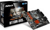
... VGA cards and CPU support list on ASRock's website without notice. Chapter 4 contains the configuration guide of the software and utilities. In this documentation, Chapter 1 and 2 contains the introduction of this motherboard, please visit our website for purchasing ASRock H110M-HDS R3.0 / H110M-DVS R3.0 / H110MDGS R3.0 motherboard, a reliable motherboard produced under ASRock's consistently stringent quality control. ASRock website http://www...
... VGA cards and CPU support list on ASRock's website without notice. Chapter 4 contains the configuration guide of the software and utilities. In this documentation, Chapter 1 and 2 contains the introduction of this motherboard, please visit our website for purchasing ASRock H110M-HDS R3.0 / H110M-DVS R3.0 / H110MDGS R3.0 motherboard, a reliable motherboard produced under ASRock's consistently stringent quality control. ASRock website http://www...

User Manual
Page 7
...6th Generation Intel® CoreTM i7/i5/i3/Pentium®/ Celeron® Processors (Socket 1151) • 4 Power Phase design • Supports CPU up to 95W • Supports Intel® Turbo Boost 2.0 Technology Chipset • Intel® H110 Memory • Dual Channel DDR4 Memory Technology... 510/530 • Pixel Shader 5.0, DirectX 12 • Max. capacity of maximum shared memory may vary from different operating systems. H110M-HDS R3.0: • Dual graphics output: Support DVI-D and HDMI ports by independent display controllers 2 English shared memory 1024MB * The size of...
...6th Generation Intel® CoreTM i7/i5/i3/Pentium®/ Celeron® Processors (Socket 1151) • 4 Power Phase design • Supports CPU up to 95W • Supports Intel® Turbo Boost 2.0 Technology Chipset • Intel® H110 Memory • Dual Channel DDR4 Memory Technology... 510/530 • Pixel Shader 5.0, DirectX 12 • Max. capacity of maximum shared memory may vary from different operating systems. H110M-HDS R3.0: • Dual graphics output: Support DVI-D and HDMI ports by independent display controllers 2 English shared memory 1024MB * The size of...
User Manual
Page 9
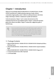
.... • 2 x USB 3.0 Ports (Supports ESD Protection (ASRock Full Spike Protection)) • 1 x RJ-45 LAN Port with LED (ACT/LINK LED and SPEED LED) • HD Audio Jacks: Line in / Front Speaker / Microphone H110M-HDS R3.0: • 1 x DVI-D Port • 1 x HDMI Port H110M-DVS R3.0: • 1 x D-Sub Port • 1 x DVI-D Port H110M-DGS R3.0: • 1 x DVI-D Port Storage •...
.... • 2 x USB 3.0 Ports (Supports ESD Protection (ASRock Full Spike Protection)) • 1 x RJ-45 LAN Port with LED (ACT/LINK LED and SPEED LED) • HD Audio Jacks: Line in / Front Speaker / Microphone H110M-HDS R3.0: • 1 x DVI-D Port • 1 x HDMI Port H110M-DVS R3.0: • 1 x D-Sub Port • 1 x DVI-D Port H110M-DGS R3.0: • 1 x DVI-D Port Storage •...

User Manual
Page 10
... setting in the BIOS, applying Untied Overclocking Technology, or using third-party overclocking tools. H110M-HDS R3.0 / H110M-DVS R3.0 / H110M-DGS R3.0 • 1 x USB 2.0 Header (Supports 2 USB 2.0 ports) (Supports ESD Protection (ASRock Full Spike Protection)) • 1 x USB 3.0 Header (Supports 2 USB 3.0 ports) (Supports ESD Protection (ASRock Full Spike Protection)) BIOS Feature • AMI UEFI Legal BIOS with multilingual GUI...
... setting in the BIOS, applying Untied Overclocking Technology, or using third-party overclocking tools. H110M-HDS R3.0 / H110M-DVS R3.0 / H110M-DGS R3.0 • 1 x USB 2.0 Header (Supports 2 USB 2.0 ports) (Supports ESD Protection (ASRock Full Spike Protection)) • 1 x USB 3.0 Header (Supports 2 USB 3.0 ports) (Supports ESD Protection (ASRock Full Spike Protection)) BIOS Feature • AMI UEFI Legal BIOS with multilingual GUI...

User Manual
Page 14
H110M-HDS R3.0 / H110M-DVS R3.0 / H110M-DGS R3.0 No. Description 1 ATX 12V Power Connector (ATX12V1) 2 CPU Fan Connector (CPU_FAN1) 3 2 x 288-pin DDR4 DIMM Slots (DDR4_A1, DDR4_B1) 4 Chassis Fan Connector (CHA_FAN1) 5 ATX Power Connector (ATXPWR1) 6 SATA3 Connectors (SATA3_2_3) 7 SATA3 Connectors (SATA3_0_1) 8 USB 3.0 Header (USB3_3_4) 9 USB 2.0 Header (USB_4_5) 10 System Panel Header (PANEL1) 11 Chassis Intrusion and Speaker Header (SPK_CI1) 12 TPM Header (TPMS1) 13 Front Panel Audio Header (HD_AUDIO1) 9 English
H110M-HDS R3.0 / H110M-DVS R3.0 / H110M-DGS R3.0 No. Description 1 ATX 12V Power Connector (ATX12V1) 2 CPU Fan Connector (CPU_FAN1) 3 2 x 288-pin DDR4 DIMM Slots (DDR4_A1, DDR4_B1) 4 Chassis Fan Connector (CHA_FAN1) 5 ATX Power Connector (ATXPWR1) 6 SATA3 Connectors (SATA3_2_3) 7 SATA3 Connectors (SATA3_0_1) 8 USB 3.0 Header (USB3_3_4) 9 USB 2.0 Header (USB_4_5) 10 System Panel Header (PANEL1) 11 Chassis Intrusion and Speaker Header (SPK_CI1) 12 TPM Header (TPMS1) 13 Front Panel Audio Header (HD_AUDIO1) 9 English

User Manual
Page 20
Before you insert the 1151-Pin CPU into the socket if above situation is unclean, or if there are any bent pins in the socket. Otherwise, the CPU will be seriously damaged. 2. H110M-HDS R3.0 / H110M-DVS R3.0 / H110M-DGS R3.0 2.1 Installing the CPU 1. Unplug all power cables before installing the CPU. 1 A B 2 15 English Do not force to insert the CPU into the socket, please check if the PnP cap is on the socket, if the CPU surface is found.
Before you insert the 1151-Pin CPU into the socket if above situation is unclean, or if there are any bent pins in the socket. Otherwise, the CPU will be seriously damaged. 2. H110M-HDS R3.0 / H110M-DVS R3.0 / H110M-DGS R3.0 2.1 Installing the CPU 1. Unplug all power cables before installing the CPU. 1 A B 2 15 English Do not force to insert the CPU into the socket, please check if the PnP cap is on the socket, if the CPU surface is found.

User Manual
Page 23
2.2 Installing the CPU Fan and Heatsink 1 2 CPU_FAN English 18
2.2 Installing the CPU Fan and Heatsink 1 2 CPU_FAN English 18

User Manual
Page 29
...Audio_L (LIN) to function correctly. ATX Power Connector (24-pin ATXPWR1) (see p.6, 7, 8, No. 2) FAN_SPEED This motherboard pro- D. FAN_VOLTAGE_CONTROL GND FAN_SPEED_CONTROL vides a 4-Pin CPU fan (Quiet Fan) connector. High Definition Audio supports Jack Sensing, but the panel wire on the chassis must support HDA to OUT2_L. MIC_RET and OUT_RET...) FAN_VOLTAGE_CONTROL GND FAN_SPEED_CONTROL (see p.6, 7, 8, No. 4) Please connect fan cables to the fan connector and match the black wire to connect a 3-Pin CPU fan, please connect it along Pin 1 and Pin 13. 24 English
...Audio_L (LIN) to function correctly. ATX Power Connector (24-pin ATXPWR1) (see p.6, 7, 8, No. 2) FAN_SPEED This motherboard pro- D. FAN_VOLTAGE_CONTROL GND FAN_SPEED_CONTROL vides a 4-Pin CPU fan (Quiet Fan) connector. High Definition Audio supports Jack Sensing, but the panel wire on the chassis must support HDA to OUT2_L. MIC_RET and OUT_RET...) FAN_VOLTAGE_CONTROL GND FAN_SPEED_CONTROL (see p.6, 7, 8, No. 4) Please connect fan cables to the fan connector and match the black wire to connect a 3-Pin CPU fan, please connect it along Pin 1 and Pin 13. 24 English
User Manual
Page 42
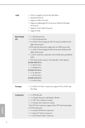
... the upper right corner of your system, such as CPU speed, DRAM frequency, SATA information, fan speed, etc. Function 1 Help 2 Load UEFI Defaults 3 Save Changes and Exit 4 Discard Changes 5 Change Language 6 Switch to "Advanced Mode" for more options. 1234 5 6 No. H110M-HDS R3.0 / H110M-DVS R3.0 / H110M-DGS R3.0 4.2 EZ Mode The EZ Mode screen appears when you...
... the upper right corner of your system, such as CPU speed, DRAM frequency, SATA information, fan speed, etc. Function 1 Help 2 Load UEFI Defaults 3 Save Changes and Exit 4 Discard Changes 5 Change Language 6 Switch to "Advanced Mode" for more options. 1234 5 6 No. H110M-HDS R3.0 / H110M-DVS R3.0 / H110M-DGS R3.0 4.2 EZ Mode The EZ Mode screen appears when you...

User Manual
Page 46
... run above its base operating frequency when the operating system requests the highest performance state. Because the UEFI software is exceeded, the CPU ratio will be lowered after a period of time. Long Duration Power Limit Configure Package Power Limit 1 in watts. When the ... frequencies and voltage points for reference purpose only, and they may improve performance. 41 English H110M-HDS R3.0 / H110M-DVS R3.0 / H110M-DGS R3.0 4.5 OC Tweaker Screen In the OC Tweaker screen, you can protect the CPU and save power, while a higher limit may not exactly match what you see on your...
... run above its base operating frequency when the operating system requests the highest performance state. Because the UEFI software is exceeded, the CPU ratio will be lowered after a period of time. Long Duration Power Limit Configure Package Power Limit 1 in watts. When the ... frequencies and voltage points for reference purpose only, and they may improve performance. 41 English H110M-HDS R3.0 / H110M-DVS R3.0 / H110M-DGS R3.0 4.5 OC Tweaker Screen In the OC Tweaker screen, you can protect the CPU and save power, while a higher limit may not exactly match what you see on your...

User Manual
Page 47
...response. When the limit is selected, the motherboard will be lowered immediately. DRAM Frequency If [Auto] is exceeded, the CPU ratio will detect the memory module(s) inserted and assign the appropriate frequency automatically. GT Frequency Configure the frequency of time until the... CPU ratio is lowered when the Long Duration Power Limit is exceeded. Short Duration Power Limit Configure Package Power Limit 2 in checkboxes. A lower limit can protect the CPU and save power, while a higher limit may improve ...
...response. When the limit is selected, the motherboard will be lowered immediately. DRAM Frequency If [Auto] is exceeded, the CPU ratio will detect the memory module(s) inserted and assign the appropriate frequency automatically. GT Frequency Configure the frequency of time until the... CPU ratio is lowered when the Long Duration Power Limit is exceeded. Short Duration Power Limit Configure Package Power Limit 2 in checkboxes. A lower limit can protect the CPU and save power, while a higher limit may improve ...

User Manual
Page 54
H110M-HDS R3.0 / H110M-DVS R3.0 / H110M-DGS R3.0 4.6 Advanced Screen In this section may set the configurations for the following items: CPU Configuration, Chipset Configuration, Storage Configuration, ACPI Configuration, USB Configuration and Trusted Computing. Active Page on Entry Select the default page when entering the UEFI setup utility. 49 English UEFI Configuration UEFI Setup Style Select the default mode when entering the UEFI setup utility. Setting wrong values in this section, you may cause the system to malfunction.
H110M-HDS R3.0 / H110M-DVS R3.0 / H110M-DGS R3.0 4.6 Advanced Screen In this section may set the configurations for the following items: CPU Configuration, Chipset Configuration, Storage Configuration, ACPI Configuration, USB Configuration and Trusted Computing. Active Page on Entry Select the default page when entering the UEFI setup utility. 49 English UEFI Configuration UEFI Setup Style Select the default mode when entering the UEFI setup utility. Setting wrong values in this section, you may cause the system to malfunction.

User Manual
Page 55
Enhanced Halt State (C1E) Enable Enhanced Halt State (C1E) for lower power consumption. 50 English It is improved. 4.6.1 CPU Configuration Intel Hyper Threading Technology Intel Hyper Threading Technology allows multiple threads to run on each core, so that the overall performance... on threaded software is recommended to enable in each processor package. CPU C7 State Support Enable C7 deep sleep state for lower power consumption. CPU C6 State Support Enable C6 deep sleep state for power saving. Active Processor Cores Select the number of...
Enhanced Halt State (C1E) Enable Enhanced Halt State (C1E) for lower power consumption. 50 English It is improved. 4.6.1 CPU Configuration Intel Hyper Threading Technology Intel Hyper Threading Technology allows multiple threads to run on each core, so that the overall performance... on threaded software is recommended to enable in each processor package. CPU C7 State Support Enable C7 deep sleep state for lower power consumption. CPU C6 State Support Enable C6 deep sleep state for power saving. Active Processor Cores Select the number of...

User Manual
Page 56
H110M-HDS R3.0 / H110M-DVS R3.0 / H110M-DGS R3.0 Package C State Support Enable CPU, PCIe, Memory, Graphics C State Support for better performance. Enable for power saving. Enable for the processor. Intel Virtualization Technology Intel Virtualization ... buffer overflow attacks. Adjacent Cache Line Prefetch Automatically prefetch the subsequent cache line while retrieving the currently requested cache line. CPU Thermal Throttling Enable CPU internal thermal control mechanisms to set of new CPU instructions that one computer system can be used by applications to keep the...
H110M-HDS R3.0 / H110M-DVS R3.0 / H110M-DGS R3.0 Package C State Support Enable CPU, PCIe, Memory, Graphics C State Support for better performance. Enable for power saving. Enable for the processor. Intel Virtualization Technology Intel Virtualization ... buffer overflow attacks. Adjacent Cache Line Prefetch Automatically prefetch the subsequent cache line while retrieving the currently requested cache line. CPU Thermal Throttling Enable CPU internal thermal control mechanisms to set of new CPU instructions that one computer system can be used by applications to keep the...

User Manual
Page 57
PCIE2 Link Speed Select the link speed for all CPU downstream devices. 52 English VT-d Intel® Virtualization Technology for PCIE1. PCIE ASPM Support This option enables/disables the ASPM support for PCIE2. PCIE1 Link ...
PCIE2 Link Speed Select the link speed for all CPU downstream devices. 52 English VT-d Intel® Virtualization Technology for PCIE1. PCIE ASPM Support This option enables/disables the ASPM support for PCIE2. PCIE1 Link ...

User Manual
Page 58
H110M-HDS R3.0 / H110M-DVS R3.0 / H110M-DGS R3.0 PCH PCIE ASPM Support This option enables/disables the ASPM support for all PCH DMI devices. PCH DMI ASPM Support This option enables/disables the ... disable to disable the integrated graphics when an external graphics card is selected, the power will start to one or more local APICs. Restore on CPU side of memory that is installed. Enable/disable IOAPIC 24-119 Entries to expand to the integrated graphics processor when the system boots up when...
H110M-HDS R3.0 / H110M-DVS R3.0 / H110M-DGS R3.0 PCH PCIE ASPM Support This option enables/disables the ASPM support for all PCH DMI devices. PCH DMI ASPM Support This option enables/disables the ... disable to disable the integrated graphics when an external graphics card is selected, the power will start to one or more local APICs. Restore on CPU side of memory that is installed. Enable/disable IOAPIC 24-119 Entries to expand to the integrated graphics processor when the system boots up when...

User Manual
Page 66
... a fan temperature source for each temperature. Fan-Tastic Tuning Select a fan mode for CPU Fan 1, or choose Customize to set 5 CPU temperatures and assign a respective fan speed for Chassis Fan 1. H110M-HDS R3.0 / H110M-DVS R3.0 / H110M-DGS R3.0 4.8 Hardware Health Event Monitoring Screen This section allows you to set 5 CPU temperatures and assign a respective fan speed for each temperature...
... a fan temperature source for each temperature. Fan-Tastic Tuning Select a fan mode for CPU Fan 1, or choose Customize to set 5 CPU temperatures and assign a respective fan speed for Chassis Fan 1. H110M-HDS R3.0 / H110M-DVS R3.0 / H110M-DGS R3.0 4.8 Hardware Health Event Monitoring Screen This section allows you to set 5 CPU temperatures and assign a respective fan speed for each temperature...


