

User Manual
Page 3
...Contents 1 1.2 Specifications 2 1.3 Motherboard Layout 5 1.4 I/O Panel 7 Chapter 2 Installation 9 2.1 Installing the CPU 10 2.2 Installing the CPU Fan and Heatsink 13 2.3 Installing Memory Modules (DIMM) 14 2.4 Expansion Slots (PCI Express Slots) 16 2.5 Onboard Headers and Connectors 17 Chapter 3 Software and Utilities Operation 21 3.1 Installing Drivers 21 3.2 ASRock Live Update & APP Shop 22 3.2.1 UI Overview 22 3.2.2 Apps 23 3.2.3 BIOS & Drivers 26 3.2.4 Setting 27 3.3 Enabling USB Ports for Windows® 7 Installation 28 Chapter 4 UEFI SETUP UTILITY 31...
...Contents 1 1.2 Specifications 2 1.3 Motherboard Layout 5 1.4 I/O Panel 7 Chapter 2 Installation 9 2.1 Installing the CPU 10 2.2 Installing the CPU Fan and Heatsink 13 2.3 Installing Memory Modules (DIMM) 14 2.4 Expansion Slots (PCI Express Slots) 16 2.5 Onboard Headers and Connectors 17 Chapter 3 Software and Utilities Operation 21 3.1 Installing Drivers 21 3.2 ASRock Live Update & APP Shop 22 3.2.1 UI Overview 22 3.2.2 Apps 23 3.2.3 BIOS & Drivers 26 3.2.4 Setting 27 3.3 Enabling USB Ports for Windows® 7 Installation 28 Chapter 4 UEFI SETUP UTILITY 31...

User Manual
Page 5
... specific information about the model you for purchasing ASRock H110M-DGS/D3 motherboard, a reliable motherboard produced under ASRock's consistently stringent quality control. In case any modifications of the software and utilities. You may find the latest VGA cards and CPU support list on ASRock's website without notice. If you require technical support related to this documentation occur, the updated version will be subject to quality and endurance. Chapter 4 contains the configuration guide of the motherboard...
... specific information about the model you for purchasing ASRock H110M-DGS/D3 motherboard, a reliable motherboard produced under ASRock's consistently stringent quality control. In case any modifications of the software and utilities. You may find the latest VGA cards and CPU support list on ASRock's website without notice. If you require technical support related to this documentation occur, the updated version will be subject to quality and endurance. Chapter 4 contains the configuration guide of the motherboard...
User Manual
Page 7
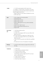
...; 2 x USB 3.0 Ports (Supports ESD Protection (ASRock Full Spike Protection)) • 1 x RJ-45 LAN Port with LED (ACT/LINK LED and SPEED LED) • HD Audio Jacks: Line in / Front Speaker / Microphone Storage • 4 x SATA3 6.0 Gb/s Connectors, support NCQ, AHCI and Hot Plug Connector • 1 x TPM Header • 1 x Chassis Intrusion and Speaker Header • 1 x CPU Fan Connector (4-pin) • 1 x Chassis Fan Connector (4-pin) * The CPU Fan Connector supports the CPU fan of maximum 1A (12W) fan power. • 1 x 24 pin ATX Power Connector • 1 x 4 pin 12V Power Connector...
...; 2 x USB 3.0 Ports (Supports ESD Protection (ASRock Full Spike Protection)) • 1 x RJ-45 LAN Port with LED (ACT/LINK LED and SPEED LED) • HD Audio Jacks: Line in / Front Speaker / Microphone Storage • 4 x SATA3 6.0 Gb/s Connectors, support NCQ, AHCI and Hot Plug Connector • 1 x TPM Header • 1 x Chassis Intrusion and Speaker Header • 1 x CPU Fan Connector (4-pin) • 1 x Chassis Fan Connector (4-pin) * The CPU Fan Connector supports the CPU fan of maximum 1A (12W) fan power. • 1 x 24 pin ATX Power Connector • 1 x 4 pin 12V Power Connector...

User Manual
Page 8
... detailed instructions. * For the updated Windows® 10 driver, please visit ASRock's website for possible damage caused by CPU temperature) • CPU/Chassis Fan multi-speed control • CASE OPEN detection • Voltage monitoring: +12V, +5V, +3.3V, CPU Vcore OS • Microsoft® Windows® 10 64-bit / 8.1 64-bit / 7 32-bit / 7 64- Please refer to the components and devices of your own risk and expense. bit * To install Windows® 7 OS, a modified installation disk with overclocking...
... detailed instructions. * For the updated Windows® 10 driver, please visit ASRock's website for possible damage caused by CPU temperature) • CPU/Chassis Fan multi-speed control • CASE OPEN detection • Voltage monitoring: +12V, +5V, +3.3V, CPU Vcore OS • Microsoft® Windows® 10 64-bit / 8.1 64-bit / 7 32-bit / 7 64- Please refer to the components and devices of your own risk and expense. bit * To install Windows® 7 OS, a modified installation disk with overclocking...
User Manual
Page 9
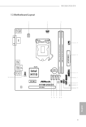
1.3 Motherboard Layout 1 2 H110M-DGS/D3 3 USB 2.0 T: USB0 B: USB1 PS2 Keyboard /Mouse ATX12V1 CPU_FAN1 4 CHA_FAN1 DVI1 DDR3_A1 (64 bit, 240-pin module) DDR3_B1 (64 bit, 240-pin module) ATXPWR1 5 USB 3.0 T: USB1 B: USB2 USB 2.0 T: USB2 B: USB3 Top: RJ-45 RoHS Intel Top: LINE IN Center: FRONT Bottom: MIC IN 1 H110 HD_AUDIO1 16 SATA3_3 SATA3_2 SATA3_1 SATA3_0 USB3_3_4 1 CMOS Battery 6 1 7 PANEL1 SPK_CI1 PLED PWRBTN HDLED RESET PCIE1 1 BIOS TPMS1 1 ROM 8 1 H110M-DGS/D3 USB4_5 9 CLRMOS1 Audio CODEC PCIE2 10 15 14 13 12 11 English 5
1.3 Motherboard Layout 1 2 H110M-DGS/D3 3 USB 2.0 T: USB0 B: USB1 PS2 Keyboard /Mouse ATX12V1 CPU_FAN1 4 CHA_FAN1 DVI1 DDR3_A1 (64 bit, 240-pin module) DDR3_B1 (64 bit, 240-pin module) ATXPWR1 5 USB 3.0 T: USB1 B: USB2 USB 2.0 T: USB2 B: USB3 Top: RJ-45 RoHS Intel Top: LINE IN Center: FRONT Bottom: MIC IN 1 H110 HD_AUDIO1 16 SATA3_3 SATA3_2 SATA3_1 SATA3_0 USB3_3_4 1 CMOS Battery 6 1 7 PANEL1 SPK_CI1 PLED PWRBTN HDLED RESET PCIE1 1 BIOS TPMS1 1 ROM 8 1 H110M-DGS/D3 USB4_5 9 CLRMOS1 Audio CODEC PCIE2 10 15 14 13 12 11 English 5

User Manual
Page 10
No. Description 1 ATX 12V Power Connector (ATX12V1) 2 CPU Fan Connector (CPU_FAN1) 3 2 x 240-pin DDR3/DDR3L DIMM Slots (DDR3_A1, DDR3_B1) 4 Chassis Fan Connector (CHA_FAN1) 5 ATX Power Connector (ATXPWR1) 6 USB 3.0 Header (USB3_3_4) 7 TPM Header (TPMS1) 8 USB 2.0 Header (USB4_5) 9 Clear CMOS Pad (CLRMOS1) 10 System Panel Header (PANEL1) 11 Chassis Intrusion and Speaker Header (SPK_CI1) 12 SATA3 Connector (SATA3_0) 13 SATA3 Connector (SATA3_1) 14 SATA3 Connector (SATA3_2) 15 SATA3 Connector (SATA3_3) 16 Front Panel Audio Header (HD_AUDIO1) 6 English
No. Description 1 ATX 12V Power Connector (ATX12V1) 2 CPU Fan Connector (CPU_FAN1) 3 2 x 240-pin DDR3/DDR3L DIMM Slots (DDR3_A1, DDR3_B1) 4 Chassis Fan Connector (CHA_FAN1) 5 ATX Power Connector (ATXPWR1) 6 USB 3.0 Header (USB3_3_4) 7 TPM Header (TPMS1) 8 USB 2.0 Header (USB4_5) 9 Clear CMOS Pad (CLRMOS1) 10 System Panel Header (PANEL1) 11 Chassis Intrusion and Speaker Header (SPK_CI1) 12 SATA3 Connector (SATA3_0) 13 SATA3 Connector (SATA3_1) 14 SATA3 Connector (SATA3_2) 15 SATA3 Connector (SATA3_3) 16 Front Panel Audio Header (HD_AUDIO1) 6 English
User Manual
Page 11
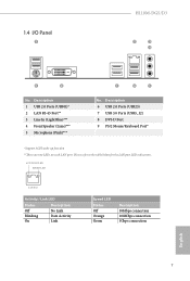
1.4 I/O Panel 1 H110M-DGS/D3 2 3 4 9 8 No. Description 6 USB 2.0 Ports (USB23) 7 USB 3.0 Ports (USB3_12) 8 DVI-D Port 9 PS/2 Mouse/Keyboard Port* * Support ACPI wake-up function ** There are two LEDs on each LAN port. ACT/LINK LED SPEED LED LAN Port Activity / Link LED Status Off Blinking On Description No Link Data Activity Link Speed LED Status Off Orange Green Description 10Mbps connection 100Mbps connection 1Gbps connection English 7 Description 1 USB 2.0 Ports (USB01)* 2 LAN RJ-45 Port** 3 Line In (Light Blue)*** 4 Front Speaker (Lime)*** 5 Microphone (Pink)*** 7 6 5...
1.4 I/O Panel 1 H110M-DGS/D3 2 3 4 9 8 No. Description 6 USB 2.0 Ports (USB23) 7 USB 3.0 Ports (USB3_12) 8 DVI-D Port 9 PS/2 Mouse/Keyboard Port* * Support ACPI wake-up function ** There are two LEDs on each LAN port. ACT/LINK LED SPEED LED LAN Port Activity / Link LED Status Off Blinking On Description No Link Data Activity Link Speed LED Status Off Orange Green Description 10Mbps connection 100Mbps connection 1Gbps connection English 7 Description 1 USB 2.0 Ports (USB01)* 2 LAN RJ-45 Port** 3 Line In (Light Blue)*** 4 Front Speaker (Lime)*** 5 Microphone (Pink)*** 7 6 5...

User Manual
Page 13
... bag that the motherboard fits into it. H110M-DGS/D3 Chapter 2 Installation This is a Micro ATX form factor motherboard. Doing so may cause physical injuries and damages to motherboard components. • In order to avoid damage from static electricity to unplug the power cord before you uninstall any motherboard settings. • Make sure to the motherboard's components, NEVER place your chassis to ensure...
... bag that the motherboard fits into it. H110M-DGS/D3 Chapter 2 Installation This is a Micro ATX form factor motherboard. Doing so may cause physical injuries and damages to motherboard components. • In order to avoid damage from static electricity to unplug the power cord before you uninstall any motherboard settings. • Make sure to the motherboard's components, NEVER place your chassis to ensure...

User Manual
Page 20
PCIe slots: PCIE1 (PCIe 2.0 x1 slot) is used for PCI Express x16 lane width graphics cards. 16 English Please read the documentation of the expansion card and make sure that the power supply is switched off or the power cord is used for the card before you start the installation. Before installing an expansion card, please make necessary hardware settings for PCI Express x1 lane width cards PCIE2 (PCIe 3.0 x16 slot) is unplugged. 2.4 Expansion Slots (PCI Express Slots) There are 2 PCI Express slots on the motherboard.
PCIe slots: PCIE1 (PCIe 2.0 x1 slot) is used for PCI Express x16 lane width graphics cards. 16 English Please read the documentation of the expansion card and make sure that the power supply is switched off or the power cord is used for the card before you start the installation. Before installing an expansion card, please make necessary hardware settings for PCI Express x1 lane width cards PCIE2 (PCIe 3.0 x16 slot) is unplugged. 2.4 Expansion Slots (PCI Express Slots) There are 2 PCI Express slots on the motherboard.

User Manual
Page 21
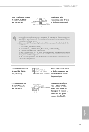
... jumper caps over the headers and connectors will cause permanent damage to turn off (S5). A front panel module mainly consists of power switch, reset switch, power LED, hard drive activity LED, speaker and etc. H110M-DGS/D3 2.5 Onboard Headers and Connectors Onboard headers and connectors are matched correctly. PWRBTN (Power Switch): Connect to the power status indicator on the chassis front panel. You may differ by chassis. RESET (Reset Switch): Connect to the hard drive activity LED on the chassis front panel. HDLED (Hard Drive Activity LED): Connect to the reset switch...
... jumper caps over the headers and connectors will cause permanent damage to turn off (S5). A front panel module mainly consists of power switch, reset switch, power LED, hard drive activity LED, speaker and etc. H110M-DGS/D3 2.5 Onboard Headers and Connectors Onboard headers and connectors are matched correctly. PWRBTN (Power Switch): Connect to the power status indicator on the chassis front panel. You may differ by chassis. RESET (Reset Switch): Connect to the hard drive activity LED on the chassis front panel. HDLED (Hard Drive Activity LED): Connect to the reset switch...
User Manual
Page 23
... audio panel. MIC_RET and OUT_RET are for the HD audio panel only. You don't need to OUT2_L. CPU Fan Connector (4-pin CPU_FAN1) (see p.5, No. 2) This motherboard pro- D. C. Chassis Fan Connector (4-pin CHA_FAN1) (see p.5, No. 4) GND FAN_VOLTAGE CHA_FAN_SPEED Please connect fan cables to the fan connector and FAN_SPEED_CONTROL match the black wire to the front audio panel. English 19 H110M-DGS/D3 Front Panel Audio Header (9-pin HD_AUDIO1) (see p.5, No. 16) OUT_RET MIC_RET PRESENCE# GN D This header is for OUT2_L J_SENSE connecting audio devices...
... audio panel. MIC_RET and OUT_RET are for the HD audio panel only. You don't need to OUT2_L. CPU Fan Connector (4-pin CPU_FAN1) (see p.5, No. 2) This motherboard pro- D. C. Chassis Fan Connector (4-pin CHA_FAN1) (see p.5, No. 4) GND FAN_VOLTAGE CHA_FAN_SPEED Please connect fan cables to the fan connector and FAN_SPEED_CONTROL match the black wire to the front audio panel. English 19 H110M-DGS/D3 Front Panel Audio Header (9-pin HD_AUDIO1) (see p.5, No. 16) OUT_RET MIC_RET PRESENCE# GN D This header is for OUT2_L J_SENSE connecting audio devices...

User Manual
Page 25
... system will be auto-detected and listed on a specific item then follow the order from top to bottom to install it. Please click Install All or follow the installation wizard to install those required drivers. H110M-DGS/D3 Chapter 3 Software and Utilities Operation 3.1 Installing Drivers The Support CD that comes with the motherboard contains necessary drivers and useful utilities that the motherboard supports. If the Main Menu does not appear automatically, locate and double click...
... system will be auto-detected and listed on a specific item then follow the order from top to bottom to install it. Please click Install All or follow the installation wizard to install those required drivers. H110M-DGS/D3 Chapter 3 Software and Utilities Operation 3.1 Installing Drivers The Support CD that comes with the motherboard contains necessary drivers and useful utilities that the motherboard supports. If the Main Menu does not appear automatically, locate and double click...
User Manual
Page 32
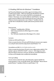
3.3 Enabling USB Ports for Windows® 7 Installation Intel® Braswell and Skylake has removed their motherboard won't work. USB2.0) and only kept the eXtensible Host Controller Interface (XHCI - Requirements • A Windows® 7 installation disk or USB drive • USB 3.0 drivers (included in the ASRock Support CD or website) • A Windows® PC • Win7 USB Patcher (included in the ASRock Support CD or website) Scenarios You have an optical disc drive, please find it...
3.3 Enabling USB Ports for Windows® 7 Installation Intel® Braswell and Skylake has removed their motherboard won't work. USB2.0) and only kept the eXtensible Host Controller Interface (XHCI - Requirements • A Windows® 7 installation disk or USB drive • USB 3.0 drivers (included in the ASRock Support CD or website) • A Windows® PC • Win7 USB Patcher (included in the ASRock Support CD or website) Scenarios You have an optical disc drive, please find it...

User Manual
Page 33
Step 4 Select the "USB Driver Folder" by clicking the red circle as shown as the picture below . Step 2 Extract the tool (Win7 USB Patcher) and launch it. If you are using ASRock's Support CD for the USB 3.0 driver, please select your system. H110M-DGS/D3 Instructions Step 1 Insert the Windows® 7 installation disk or USB drive to your CD-ROM. 29 English Step 3 Select the "Win7 Folder" from Step1 by clicking the red circle as shown as the picture below .
Step 4 Select the "USB Driver Folder" by clicking the red circle as shown as the picture below . Step 2 Extract the tool (Win7 USB Patcher) and launch it. If you are using ASRock's Support CD for the USB 3.0 driver, please select your system. H110M-DGS/D3 Instructions Step 1 Insert the Windows® 7 installation disk or USB drive to your CD-ROM. 29 English Step 3 Select the "Win7 Folder" from Step1 by clicking the red circle as shown as the picture below .

User Manual
Page 41
... the CPU and save power, while a higher limit may improve performance. Primary Timing CAS# Latency (tCL) The time between a bank active command and issuing the precharge command. 37 English H110M-DGS/D3 Long Duration Maintained Configure the period of the data in watts. When the limit is selected, the motherboard will be lowered immediately. DRAM Reference Clock Select Auto for optimized settings.
... the CPU and save power, while a higher limit may improve performance. Primary Timing CAS# Latency (tCL) The time between a bank active command and issuing the precharge command. 37 English H110M-DGS/D3 Long Duration Maintained Configure the period of the data in watts. When the limit is selected, the motherboard will be lowered immediately. DRAM Reference Clock Select Auto for optimized settings.
User Manual
Page 52
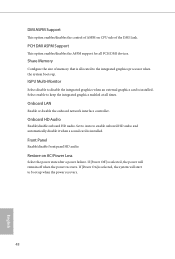
... power will start to keep the integrated graphics enabled at all PCH DMI devices. Onboard HD Audio Enable/disable onboard HD audio. Front Panel Enable/disable front panel HD audio. Restore on CPU side of the DMI Link. If [Power Off] is installed. Onboard LAN Enable or disable the onboard network interface controller. If [Power On] is installed. DMI ASPM Support This option enables/disables the control of ASPM on AC/Power Loss Select the power state after a power failure. Select enable to boot up . Set to Auto to the integrated graphics processor...
... power will start to keep the integrated graphics enabled at all PCH DMI devices. Onboard HD Audio Enable/disable onboard HD audio. Front Panel Enable/disable front panel HD audio. Restore on CPU side of the DMI Link. If [Power Off] is installed. Onboard LAN Enable or disable the onboard network interface controller. If [Power On] is installed. DMI ASPM Support This option enables/disables the control of ASPM on AC/Power Loss Select the power state after a power failure. Select enable to boot up . Set to Auto to the integrated graphics processor...
User Manual
Page 59
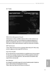
Please setup network configuration before using UEFI Tech Service. Easy Driver Installer For users that installs the LAN driver to your PC. In order to prevent users from our support CD, Easy Driver Installer is specifically designed for the dual OS platform/multi-OS platform users to easily customize and manage the boot menu. *Please connect more than one boot devices to other required drivers automatically. UEFI Tech Service Contact ASRock Tech Service if you are required. You may schedule...
Please setup network configuration before using UEFI Tech Service. Easy Driver Installer For users that installs the LAN driver to your PC. In order to prevent users from our support CD, Easy Driver Installer is specifically designed for the dual OS platform/multi-OS platform users to easily customize and manage the boot menu. *Please connect more than one boot devices to other required drivers automatically. UEFI Tech Service Contact ASRock Tech Service if you are required. You may schedule...
User Manual
Page 60
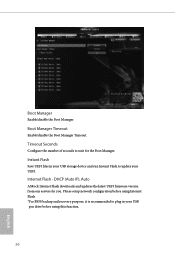
... update your UEFI. Internet Flash - Instant Flash Save UEFI files in your USB storage device and run Instant Flash to wait for you. Boot Manager Enable/disable the Boot Manager. DHCP (Auto IP), Auto ASRock Internet Flash downloads and updates the latest UEFI firmware version from our servers for the Boot Manager. Please setup network configuration before using Internet Flash. *For BIOS backup and recovery purpose, it is recommended to plug in your USB pen drive before using this function. 56 English Boot Manager Timeout Enable/disable the Boot...
... update your UEFI. Internet Flash - Instant Flash Save UEFI files in your USB storage device and run Instant Flash to wait for you. Boot Manager Enable/disable the Boot Manager. DHCP (Auto IP), Auto ASRock Internet Flash downloads and updates the latest UEFI firmware version from our servers for the Boot Manager. Please setup network configuration before using Internet Flash. *For BIOS backup and recovery purpose, it is recommended to plug in your USB pen drive before using this function. 56 English Boot Manager Timeout Enable/disable the Boot...

User Manual
Page 61
UEFI Download Server Select a server to configure internet connection settings for Internet Flash. Internet Setting Enable or disable sound effects in the setup utility. H110M-DGS/D3 Network Configuration Use this to download the UEFI firmware. 57 English
UEFI Download Server Select a server to configure internet connection settings for Internet Flash. Internet Setting Enable or disable sound effects in the setup utility. H110M-DGS/D3 Network Configuration Use this to download the UEFI firmware. 57 English

User Manual
Page 64
... and press enter to enable or disable support for the administrator account. Intel(R) Platform Trust Technology Enable/disable Intel PTT in the UEFI Setup Utility. Users are unable to use discrete TPM Module. 60 English You may set or change the password for the system. Supervisor Password Set or change the settings in the UEFI Setup Utility. Secure Boot Use this option to change the password for Windows 8.1 Secure Boot. User Password Set or change the supervisor/user password for the user account. 4.9 Security Screen In this...
... and press enter to enable or disable support for the administrator account. Intel(R) Platform Trust Technology Enable/disable Intel PTT in the UEFI Setup Utility. Users are unable to use discrete TPM Module. 60 English You may set or change the password for the system. Supervisor Password Set or change the settings in the UEFI Setup Utility. Secure Boot Use this option to change the password for Windows 8.1 Secure Boot. User Password Set or change the supervisor/user password for the user account. 4.9 Security Screen In this...


