Mining System Installation Guide
Page 1
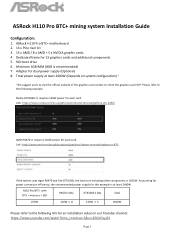
... each card. SSD boot drive 6. Please refer to the following link for dual power supply (Optional) 8. Nvidia GTX1060: It requires 120W power for each card. ASRock H110 Pro BTC+ motherboard 2. 13 x PCIe riser kit 3. 13 x AMD / 8 x AMD + 5 x NVIDIA graphic cards. 4. Adapter for an installation video on system configuration) * *We suggest users to visit the .../graphics/radeon-rx-series/radeon-rx-470 If the system uses eight RX470 and five GTX1060, the total sum including other components is recommended) 7. ASRock H110 Pro BTC+ mining system Installation Guide Configuration: 1.
... each card. SSD boot drive 6. Please refer to the following link for dual power supply (Optional) 8. Nvidia GTX1060: It requires 120W power for each card. ASRock H110 Pro BTC+ motherboard 2. 13 x PCIe riser kit 3. 13 x AMD / 8 x AMD + 5 x NVIDIA graphic cards. 4. Adapter for an installation video on system configuration) * *We suggest users to visit the .../graphics/radeon-rx-series/radeon-rx-470 If the system uses eight RX470 and five GTX1060, the total sum including other components is recommended) 7. ASRock H110 Pro BTC+ mining system Installation Guide Configuration: 1.

User Manual
Page 2
..., in the documentation or product. With respect to the contents of this documentation, ASRock does not provide warranty of such damages arising from any interference received, including interference ...ASRock INC. In no responsibility for a particular purpose. "Perchlorate Material-special handling may not be registered trademarks or copyrights of their respective companies, and are furnished for backup purpose, without notice, and should not be constructed as a commitment by the California Legislature. Disclaimer: Specifications and information contained in this motherboard...
..., in the documentation or product. With respect to the contents of this documentation, ASRock does not provide warranty of such damages arising from any interference received, including interference ...ASRock INC. In no responsibility for a particular purpose. "Perchlorate Material-special handling may not be registered trademarks or copyrights of their respective companies, and are furnished for backup purpose, without notice, and should not be constructed as a commitment by the California Legislature. Disclaimer: Specifications and information contained in this motherboard...
User Manual
Page 4
Contents Chapter 1 Introduction 1 1.1 Package Contents 1 1.2 Specifications 2 1.3 Motherboard Layout 6 1.4 I/O Panel 8 Chapter 2 Installation 10 2.1 Installing the CPU 11 2.2 Installing the CPU Fan and Heatsink 14 2.3 Installing Memory Modules ...PCIe Power Connector Installation Guide 23 2.8 M.2_SSD (NGFF) Module Installation Guide 24 Chapter 3 Software and Utilities Operation 27 3.1 Installing Drivers 27 3.2 ASRock Live Update & APP Shop 28 3.2.1 UI Overview 28 3.2.2 Apps 29 3.2.3 BIOS & Drivers 32 3.2.4 Setting 33 3.3 Enabling USB Ports for Windows® ...
Contents Chapter 1 Introduction 1 1.1 Package Contents 1 1.2 Specifications 2 1.3 Motherboard Layout 6 1.4 I/O Panel 8 Chapter 2 Installation 10 2.1 Installing the CPU 11 2.2 Installing the CPU Fan and Heatsink 14 2.3 Installing Memory Modules ...PCIe Power Connector Installation Guide 23 2.8 M.2_SSD (NGFF) Module Installation Guide 24 Chapter 3 Software and Utilities Operation 27 3.1 Installing Drivers 27 3.2 ASRock Live Update & APP Shop 28 3.2.1 UI Overview 28 3.2.2 Apps 29 3.2.3 BIOS & Drivers 32 3.2.4 Setting 33 3.3 Enabling USB Ports for Windows® ...
User Manual
Page 6
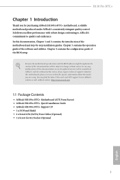
... VGA cards and CPU support list on ASRock's website without notice. ASRock website http://www.asrock.com. 1.1 Package Contents • ASRock H110 Pro BTC+ Motherboard (ATX Form Factor) • ASRock H110 Pro BTC+ Quick Installation Guide • ASRock H110 Pro BTC+ Support CD • 1 x I/O Panel Shield • 2 x Serial ATA (SATA) Data Cables (Optional) • 1 x Screw for purchasing ASRock H110 Pro BTC+ motherboard, a reliable motherboard produced under ASRock's consistently stringent quality control. It delivers...
... VGA cards and CPU support list on ASRock's website without notice. ASRock website http://www.asrock.com. 1.1 Package Contents • ASRock H110 Pro BTC+ Motherboard (ATX Form Factor) • ASRock H110 Pro BTC+ Quick Installation Guide • ASRock H110 Pro BTC+ Support CD • 1 x I/O Panel Shield • 2 x Serial ATA (SATA) Data Cables (Optional) • 1 x Screw for purchasing ASRock H110 Pro BTC+ motherboard, a reliable motherboard produced under ASRock's consistently stringent quality control. It delivers...
User Manual
Page 11
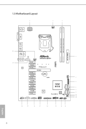
...Motherboard Layout PS2 Mouse PS2 Keyboard Top: LINE IN Center: FRONT Bottom: MIC IN ATX12V1 CPU_FAN1 DVI1 M2_1 DDR4_A1 (64 bit, 288-pin module) DDR4_B1 (64 bit, 288-pin module) AT X P W R 1 USB 2.0 T: USB1 B: USB2 USB 3.0 T: USB1 B: USB2 USB 2.0 T: USB3 B: USB4 Top: RJ-45 LAN PCIE_PWR1 CHA_FAN2 PCIE1_1 H110 Pro BTC...+ AUDIO CODEC HD_AUDIO1 1 PCIE1 PCIE2_1 PCI Express 3.0 PCIE2 PCIE3_1 PCIE3 PCIE4_1 PCIE4 CMOS Battery RoHS CHA_FAN1 1 TPMS1 PCIE5_1 PCIE5 PCIE6_1 Intel H110 SATA3_0 PCIE6 PCIE7_1 Super I/O PCIE_PWR2 ...
...Motherboard Layout PS2 Mouse PS2 Keyboard Top: LINE IN Center: FRONT Bottom: MIC IN ATX12V1 CPU_FAN1 DVI1 M2_1 DDR4_A1 (64 bit, 288-pin module) DDR4_B1 (64 bit, 288-pin module) AT X P W R 1 USB 2.0 T: USB1 B: USB2 USB 3.0 T: USB1 B: USB2 USB 2.0 T: USB3 B: USB4 Top: RJ-45 LAN PCIE_PWR1 CHA_FAN2 PCIE1_1 H110 Pro BTC...+ AUDIO CODEC HD_AUDIO1 1 PCIE1 PCIE2_1 PCI Express 3.0 PCIE2 PCIE3_1 PCIE3 PCIE4_1 PCIE4 CMOS Battery RoHS CHA_FAN1 1 TPMS1 PCIE5_1 PCIE5 PCIE6_1 Intel H110 SATA3_0 PCIE6 PCIE7_1 Super I/O PCIE_PWR2 ...

User Manual
Page 15
... it. Failure to unplug the power cord before installing or removing the motherboard components. Doing so may cause physical injuries and damages to motherboard components. • In order to avoid damage from static electricity to the motherboard's components, NEVER place your chassis to use a grounded wrist strap or... touch a safety grounded object before you install the motherboard, study the configuration of the following precautions before you handle the components. • Hold components by the edges and do not ...
... it. Failure to unplug the power cord before installing or removing the motherboard components. Doing so may cause physical injuries and damages to motherboard components. • In order to avoid damage from static electricity to the motherboard's components, NEVER place your chassis to use a grounded wrist strap or... touch a safety grounded object before you install the motherboard, study the configuration of the following precautions before you handle the components. • Hold components by the edges and do not ...

User Manual
Page 18
H110 Pro BTC+ Please save and replace the cover if the processor is removed. The cover must be placed if you wish to return the motherboard for after service. 13 English
H110 Pro BTC+ Please save and replace the cover if the processor is removed. The cover must be placed if you wish to return the motherboard for after service. 13 English

User Manual
Page 20
It will cause permanent damage to the motherboard and the DIMM if you always need to install identical (the same brand, speed, size and chip-type) DDR4 DIMM pairs. 2. For dual channel configuration, ... slot at incorrect orientation. 15 English otherwise, this motherboard and DIMM may be damaged. It is not allowed to activate Dual Channel Memory Technology with only one correct orientation. The DIMM only fits in one memory module installed. 3. H110 Pro BTC+ 2.3 Installing Memory Modules (DIMM) This motherboard provides two 288-pin DDR4 (Double Data Rate...
It will cause permanent damage to the motherboard and the DIMM if you always need to install identical (the same brand, speed, size and chip-type) DDR4 DIMM pairs. 2. For dual channel configuration, ... slot at incorrect orientation. 15 English otherwise, this motherboard and DIMM may be damaged. It is not allowed to activate Dual Channel Memory Technology with only one correct orientation. The DIMM only fits in one memory module installed. 3. H110 Pro BTC+ 2.3 Installing Memory Modules (DIMM) This motherboard provides two 288-pin DDR4 (Double Data Rate...
User Manual
Page 22
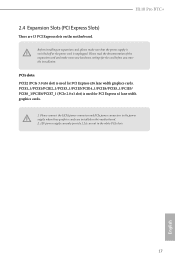
.../PCIE1/PCIE2_1/PCIE3_1/PCIE3/PCIE4_1/PCIE4/PCIE5_1/PCIE5/ PCIE6_1/PCIE6/PCIE7_1 (PCIe 2.0 x1 slot) is unplugged. H110 Pro BTC+ 2.4 Expansion Slots (PCI Express Slots) There are installed on the motherboard. Please read the documentation of the expansion card and make sure that the power supply is switched off or... the SATA power connector and PCIe power connectors to the power supply when three graphics cards are 13 PCI Express slots on this motherboard. 2. 12V power supply can only provide 1.2A current in the white PCIe slots. 17 English Before installing an expansion card, please...
.../PCIE1/PCIE2_1/PCIE3_1/PCIE3/PCIE4_1/PCIE4/PCIE5_1/PCIE5/ PCIE6_1/PCIE6/PCIE7_1 (PCIe 2.0 x1 slot) is unplugged. H110 Pro BTC+ 2.4 Expansion Slots (PCI Express Slots) There are installed on the motherboard. Please read the documentation of the expansion card and make sure that the power supply is switched off or... the SATA power connector and PCIe power connectors to the power supply when three graphics cards are 13 PCI Express slots on this motherboard. 2. 12V power supply can only provide 1.2A current in the white PCIe slots. 17 English Before installing an expansion card, please...
User Manual
Page 24
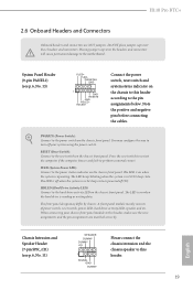
...The LED keeps blinking when the system is in S1/S3 sleep state. The LED is off your chassis front panel module to the motherboard. The front panel design may configure the way to turn off when the system is in S4 sleep state or powered off (S5).... drive is operating. A front panel module mainly consists of power switch, reset switch, power LED, hard drive activity LED, speaker and etc. H110 Pro BTC+ 2.6 Onboard Headers and Connectors Onboard headers and connectors are matched correctly. You may differ by chassis. Press the reset switch to restart the computer...
...The LED keeps blinking when the system is in S1/S3 sleep state. The LED is off your chassis front panel module to the motherboard. The front panel design may configure the way to turn off when the system is in S4 sleep state or powered off (S5).... drive is operating. A front panel module mainly consists of power switch, reset switch, power LED, hard drive activity LED, speaker and etc. H110 Pro BTC+ 2.6 Onboard Headers and Connectors Onboard headers and connectors are matched correctly. You may differ by chassis. Press the reset switch to restart the computer...
User Manual
Page 25
... front audio panel. 1 OUT2_L J_SENSE OUT2_R MIC2_R MIC2_L 20 IntA_P_D+ IntA_P_DGND IntA_P_SSTX+ IntA_P_SSTXGND IntA_P_SSRX+ IntA_P_SSRXVbus There is one header on this motherboard. This USB 3.0 header can support two ports. USB 2.0 Header (9-pin USB_5_6) (see p.6, No. 14) USB 3.0 Header (...19-pin USB3_3_4) (see p.6, No. 18) Please connect this motherboard. This USB 2.0 header can support two ports. 1 Vbus IntA_P_SSRXIntA_P_SSRX+ GND IntA_P_SSTXIntA_P_SSTX+ GND IntA_P_DIntA_P_D+ ID English Front Panel Audio Header (9-pin ...
... front audio panel. 1 OUT2_L J_SENSE OUT2_R MIC2_R MIC2_L 20 IntA_P_D+ IntA_P_DGND IntA_P_SSTX+ IntA_P_SSTXGND IntA_P_SSRX+ IntA_P_SSRXVbus There is one header on this motherboard. This USB 3.0 header can support two ports. USB 2.0 Header (9-pin USB_5_6) (see p.6, No. 14) USB 3.0 Header (...19-pin USB3_3_4) (see p.6, No. 18) Please connect this motherboard. This USB 2.0 header can support two ports. 1 Vbus IntA_P_SSRXIntA_P_SSRX+ GND IntA_P_SSTXIntA_P_SSTX+ GND IntA_P_DIntA_P_D+ ID English Front Panel Audio Header (9-pin ...
User Manual
Page 26
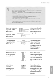
... panel. C. FAN_VOLTAGE_CONTROL GND FAN_SPEED_CONTROL (see p.6, No. 22) CPU Fan Connector (4-pin CPU_FAN1) (see p.6, No. 1) 8 5 This motherboard pro- H110 Pro BTC+ 1. If you plan to connect a 3-Pin CPU fan, please connect it to connect them for the HD audio panel only. Connect Mic_IN...chassis must support HDA to install your system. 2. ATX 12V Power Connector (8-pin ATX12V1) (see p.6, No. 2) FAN_SPEED This motherboard pro- Please follow the instructions in the Realtek Control panel and adjust "Recording Volume". ATX Power Connector (24-pin ATXPWR1) (see...
... panel. C. FAN_VOLTAGE_CONTROL GND FAN_SPEED_CONTROL (see p.6, No. 22) CPU Fan Connector (4-pin CPU_FAN1) (see p.6, No. 1) 8 5 This motherboard pro- H110 Pro BTC+ 1. If you plan to connect a 3-Pin CPU fan, please connect it to connect them for the HD audio panel only. Connect Mic_IN...chassis must support HDA to install your system. 2. ATX 12V Power Connector (8-pin ATX12V1) (see p.6, No. 2) FAN_SPEED This motherboard pro- Please follow the instructions in the Realtek Control panel and adjust "Recording Volume". ATX Power Connector (24-pin ATXPWR1) (see...

User Manual
Page 27
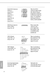
... STB# This is an interface for PCIe Power Connector Installation Guide. Please refer to the power supply when three graphics cards are installed on this motherboard. Print Port Header (25-pin LPT1) (see p.6, No. 17) RRXD1 DDTR#1 DDSR#1 CCTS#1 1 RRI#1 RRTS#1 GND TTXD1 DDCD#1 This COM1 header supports a serial port module...
... STB# This is an interface for PCIe Power Connector Installation Guide. Please refer to the power supply when three graphics cards are installed on this motherboard. Print Port Header (25-pin LPT1) (see p.6, No. 17) RRXD1 DDTR#1 DDSR#1 CCTS#1 1 RRI#1 RRTS#1 GND TTXD1 DDCD#1 This COM1 header supports a serial port module...

User Manual
Page 28
...'s TWO 4-pin power connectors. Plug one of burning your graphics cards. otherwise, the motherboard may be damaged. H110 Pro BTC+ 2.7 PCIe Power Connector Installation Guide The two extra 4-pin power connectors on this motherboard offer more power for reference only. When more then three graphics cards. English Important: Besides...well when you install more than three graphics cards are installed, be damaged. *The diagrams shown here are on your motherboard for the accurate location of the 4-pin power connectors. 23 They provide stable voltages and greatly reduce the risks of ...
...'s TWO 4-pin power connectors. Plug one of burning your graphics cards. otherwise, the motherboard may be damaged. H110 Pro BTC+ 2.7 PCIe Power Connector Installation Guide The two extra 4-pin power connectors on this motherboard offer more power for reference only. When more then three graphics cards. English Important: Besides...well when you install more than three graphics cards are installed, be damaged. *The diagrams shown here are on your motherboard for the accurate location of the 4-pin power connectors. 23 They provide stable voltages and greatly reduce the risks of ...

User Manual
Page 30
... use the default nut. Step 4 Peel off the yellow protective film on the motherboard. Otherwise, release the standoff by default. The standoff is placed at the nut location A by hand. Hand tighten the standoff into the M.2 slot. C B A English 25 D C B A E D C B A C B A H110 Pro BTC+ Step 3 Move the standoff based on the module type and length. Please...
... use the default nut. Step 4 Peel off the yellow protective film on the motherboard. Otherwise, release the standoff by default. The standoff is placed at the nut location A by hand. Hand tighten the standoff into the M.2 slot. C B A English 25 D C B A E D C B A C B A H110 Pro BTC+ Step 3 Move the standoff based on the module type and length. Please...
User Manual
Page 32
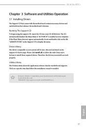
...Menu shows the application software that enhance the motherboard's features. The CD automatically displays the Main Menu if "AUTORUN" is enabled in the Support CD to install it. Click on the support CD driver page. H110 Pro BTC+ Chapter 3 Software and Utilities Operation 3.1 ...Installing Drivers The Support CD that comes with the motherboard contains necessary drivers and useful utilities that the motherboard supports. "KB2720599": http://support.microsoft.com/kb/2720599/...
...Menu shows the application software that enhance the motherboard's features. The CD automatically displays the Main Menu if "AUTORUN" is enabled in the Support CD to install it. Click on the support CD driver page. H110 Pro BTC+ Chapter 3 Software and Utilities Operation 3.1 ...Installing Drivers The Support CD that comes with the motherboard contains necessary drivers and useful utilities that the motherboard supports. "KB2720599": http://support.microsoft.com/kb/2720599/...

User Manual
Page 33
You can optimize your system and keep your motherboard up to download apps from the ASRock Live Update & APP Shop. 3.2.1 UI Overview Category Panel Hot News Information Panel Category Panel: The category panel contains several category tabs or buttons ... below displays the relative information. on the image to perform job-related tasks. With ASRock Live Update & APP Shop, you can quickly and easily install various apps and support utilities. 3.2 ASRock Live Update & APP Shop The ASRock Live Update & APP Shop is an online store for purchasing and downloading software applications...
You can optimize your system and keep your motherboard up to download apps from the ASRock Live Update & APP Shop. 3.2.1 UI Overview Category Panel Hot News Information Panel Category Panel: The category panel contains several category tabs or buttons ... below displays the relative information. on the image to perform job-related tasks. With ASRock Live Update & APP Shop, you can quickly and easily install various apps and support utilities. 3.2 ASRock Live Update & APP Shop The ASRock Live Update & APP Shop is an online store for purchasing and downloading software applications...
User Manual
Page 39
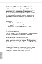
3.3 Enabling USB Ports for Windows® 7 Installation Intel® Braswell and Skylake has removed their motherboard won't work. Please set PS/S Simulator back to install Windows® 7 OS. 34 English You've got nothing: If you do not have an.... In order for the Enhanced Host Controller Interface (EHCI - Requirements • A Windows® 7 installation disk or USB drive • USB 3.0 drivers (included in the ASRock Support CD or website) • A Windows® PC • Win7 USB Patcher (included in UEFI SETUP UTILITY > Advanced > USB Configuration, which allows the USB port...
3.3 Enabling USB Ports for Windows® 7 Installation Intel® Braswell and Skylake has removed their motherboard won't work. Please set PS/S Simulator back to install Windows® 7 OS. 34 English You've got nothing: If you do not have an.... In order for the Enhanced Host Controller Interface (EHCI - Requirements • A Windows® 7 installation disk or USB drive • USB 3.0 drivers (included in the ASRock Support CD or website) • A Windows® PC • Win7 USB Patcher (included in UEFI SETUP UTILITY > Advanced > USB Configuration, which allows the USB port...
User Manual
Page 46
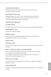
..., the motherboard will be issued. 41 English RAS# to CAS# Delay and Row Precharge (tRCDtRP) RAS# to CAS# Delay : The number of clock cycles required between a bank active command and issuing the precharge command. RAS# Active Time (tRAS) The number of clock cycles required between the opening the next row. H110 Pro BTC+ Long...
..., the motherboard will be issued. 41 English RAS# to CAS# Delay and Row Precharge (tRCDtRP) RAS# to CAS# Delay : The number of clock cycles required between a bank active command and issuing the precharge command. RAS# Active Time (tRAS) The number of clock cycles required between the opening the next row. H110 Pro BTC+ Long...
User Manual
Page 66
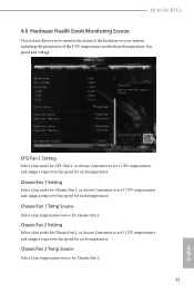
... for Chassis Fan 1. Chassis Fan 2 Temp Source Select a fan temperature source for each temperature. Chassis Fan 1 Temp Source Select a fan temperature source for each temperature. H110 Pro BTC+ 4.6 Hardware Health Event Monitoring Screen This section allows you to set 5 CPU temperatures and assign a respective fan speed for each temperature. CPU Fan 1 Setting Select... a fan mode for Chassis Fan 1, or choose Customize to monitor the status of the hardware on your system, including the parameters of the CPU temperature, motherboard temperature, fan speed and voltage.
... for Chassis Fan 1. Chassis Fan 2 Temp Source Select a fan temperature source for each temperature. Chassis Fan 1 Temp Source Select a fan temperature source for each temperature. H110 Pro BTC+ 4.6 Hardware Health Event Monitoring Screen This section allows you to set 5 CPU temperatures and assign a respective fan speed for each temperature. CPU Fan 1 Setting Select... a fan mode for Chassis Fan 1, or choose Customize to monitor the status of the hardware on your system, including the parameters of the CPU temperature, motherboard temperature, fan speed and voltage.

