
User Manual
Page 3
... 4 1.2 Specifications 4 1.3 Motherboard Layout (GE Pro-M 6 1.4 Motherboard Layout (GE Pro-HT 7 1.5 ASRock I/OTM (GE Pro-M / GE Pro-HT 8 2 Installation 9 2.1 Screw Holes 9 2.2 Pre-installation Precautions 9 2.3 CPU Installation 9 2.4 Installation of Heatsink and CPU fan 10 2.5 Installation of Memory Modules (DIMM 10 2.6 Expansion Slots 11 2.7 Jumpers Setup 12 2.8 Connectors 12 3 BIOS Setup 15 3.1 BIOS Setup Utility 15 3.1.1 BIOS Menu Bar 15 3.1.2 Legend Bar 15 3.2 Main Menu 16 3.3 Advanced, Security, Power, Boot, and Exit Menus ..... 18 4 Software Support 19 4.1 Installing...
... 4 1.2 Specifications 4 1.3 Motherboard Layout (GE Pro-M 6 1.4 Motherboard Layout (GE Pro-HT 7 1.5 ASRock I/OTM (GE Pro-M / GE Pro-HT 8 2 Installation 9 2.1 Screw Holes 9 2.2 Pre-installation Precautions 9 2.3 CPU Installation 9 2.4 Installation of Heatsink and CPU fan 10 2.5 Installation of Memory Modules (DIMM 10 2.6 Expansion Slots 11 2.7 Jumpers Setup 12 2.8 Connectors 12 3 BIOS Setup 15 3.1 BIOS Setup Utility 15 3.1.1 BIOS Menu Bar 15 3.1.2 Legend Bar 15 3.2 Main Menu 16 3.3 Advanced, Security, Power, Boot, and Exit Menus ..... 18 4 Software Support 19 4.1 Installing...

User Manual
Page 4
... BIOS setup information. 1.1 Package Contents ASRock GE Pro-M or GE Pro-HT motherboard (Micro ATX form factor: 9.6" x 9.6", 24.4 x 24.4 cm) ASRock GE Pro-M / GE Pro-HT Quick Installation Guide ASRock Intel-SiS Support CD 1 cable for IDE devices (1 x ATA 66/100/133) 1 cable for floppy drive (1 x ribbon cable) 1 ASRock I/O shield 1 COM port bracket 1.2 Specifications Platform: Micro ATX form factor (9.6" x 9.6", 24.4 x 24.4 cm) CPU: Socket 478 for SDR: DIMM3 and DIMM4 (PC100/ PC133), Max. 2GB IDE: IDE1: ATA 133 / Ultra DMA Mode 6; Chapter 3 and 4 contain basic BIOS setup and Support...
... BIOS setup information. 1.1 Package Contents ASRock GE Pro-M or GE Pro-HT motherboard (Micro ATX form factor: 9.6" x 9.6", 24.4 x 24.4 cm) ASRock GE Pro-M / GE Pro-HT Quick Installation Guide ASRock Intel-SiS Support CD 1 cable for IDE devices (1 x ATA 66/100/133) 1 cable for floppy drive (1 x ribbon cable) 1 ASRock I/O shield 1 COM port bracket 1.2 Specifications Platform: Micro ATX form factor (9.6" x 9.6", 24.4 x 24.4 cm) CPU: Socket 478 for SDR: DIMM3 and DIMM4 (PC100/ PC133), Max. 2GB IDE: IDE1: ATA 133 / Ultra DMA Mode 6; Chapter 3 and 4 contain basic BIOS setup and Support...

User Manual
Page 5
... heatsink when you resume the system. ACPI 1.1 compliance wake up events; About the setting of the system or damage the CPU. 5 Although GE Pro-M/GE Pro-HT offers stepless control, it is detected, the system will automatically shutdown. CPU fan tachometer; Supports "Plug and Play"; Supports jumperfree; Please refer to protect CPU life (ASRock U-COP) (see CAUTION 2);Chassis temperature sensing; Frequencies other than the recommended CPU bus frequency may not work properly under Microsoft® Windows...
... heatsink when you resume the system. ACPI 1.1 compliance wake up events; About the setting of the system or damage the CPU. 5 Although GE Pro-M/GE Pro-HT offers stepless control, it is detected, the system will automatically shutdown. CPU fan tachometer; Supports "Plug and Play"; Supports jumperfree; Please refer to protect CPU life (ASRock U-COP) (see CAUTION 2);Chassis temperature sensing; Frequencies other than the recommended CPU bus frequency may not work properly under Microsoft® Windows...

User Manual
Page 6
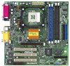
... IDE connector (IDE1, Blue) 8 Secondary IDE connector (IDE2, Black) 9 Chassis fan connector (CHA_FAN1) 10 Floppy connector (FLOPPY1) 11 Flash Memory 12 System panel connector (PANEL1) 13 USB 2.0 header (USB45) 14 Infrared module connector (IR1) 15 Chassis speaker connector (SPEAKER1) 16 South Bridge controller 17 Clear CMOS (CLRCMOS1) 18 PCI slots (PCI 1- 3) 19 AUDIO CODEC 20 Front panel audio connector (AUDIO1) 21 LAN PHY 22 PS2_USB_PWR1 jumper 23 Internal audio connector: AUX1(white) 24 Internal audio connector: CD1 (black) 25 Serial port connector (COM1) 26 AMR slot 27 AGP slot...
... IDE connector (IDE1, Blue) 8 Secondary IDE connector (IDE2, Black) 9 Chassis fan connector (CHA_FAN1) 10 Floppy connector (FLOPPY1) 11 Flash Memory 12 System panel connector (PANEL1) 13 USB 2.0 header (USB45) 14 Infrared module connector (IR1) 15 Chassis speaker connector (SPEAKER1) 16 South Bridge controller 17 Clear CMOS (CLRCMOS1) 18 PCI slots (PCI 1- 3) 19 AUDIO CODEC 20 Front panel audio connector (AUDIO1) 21 LAN PHY 22 PS2_USB_PWR1 jumper 23 Internal audio connector: AUX1(white) 24 Internal audio connector: CD1 (black) 25 Serial port connector (COM1) 26 AMR slot 27 AGP slot...

User Manual
Page 7
... IDE connector (IDE1, Blue) 8 Secondary IDE connector (IDE2, Black) 9 Chassis fan connector (CHA_FAN1) 10 Floppy connector (FLOPPY1) 11 Flash Memory 12 System panel connector (PANEL1) 13 USB 2.0 header (USB45) 14 Infrared module connector (IR1) 15 Chassis speaker connector (SPEAKER1) 16 South Bridge controller 17 Clear CMOS (CLRCMOS1) 18 PCI slots (PCI 1- 3) 19 AUDIO CODEC 20 Front panel audio connector (AUDIO1) 21 LAN PHY 22 PS2_USB_PWR1 jumper 23 Internal audio connector: AUX1(white) 24 Internal audio connector: CD1 (black) 25 Serial port connector (COM1) 26 AMR slot 27 AGP slot...
... IDE connector (IDE1, Blue) 8 Secondary IDE connector (IDE2, Black) 9 Chassis fan connector (CHA_FAN1) 10 Floppy connector (FLOPPY1) 11 Flash Memory 12 System panel connector (PANEL1) 13 USB 2.0 header (USB45) 14 Infrared module connector (IR1) 15 Chassis speaker connector (SPEAKER1) 16 South Bridge controller 17 Clear CMOS (CLRCMOS1) 18 PCI slots (PCI 1- 3) 19 AUDIO CODEC 20 Front panel audio connector (AUDIO1) 21 LAN PHY 22 PS2_USB_PWR1 jumper 23 Internal audio connector: AUX1(white) 24 Internal audio connector: CD1 (black) 25 Serial port connector (COM1) 26 AMR slot 27 AGP slot...
User Manual
Page 9
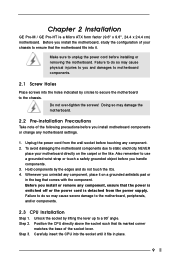
... switched off or the power cord is a Micro ATX form factor (9.6" x 9.6", 24.4 x 24.4 cm) motherboard. Step 2. To avoid damaging the motherboard components due to use a grounded wrist strap or touch a safety grounded object before installing or removing the motherboard. Whenever you uninstall any motherboard settings. 1. Failure to do not touch the ICs. 4. Chapter 2 Installation GE Pro-M / GE Pro-HT is detached from the wall socket before you install motherboard components or change...
... switched off or the power cord is a Micro ATX form factor (9.6" x 9.6", 24.4 x 24.4 cm) motherboard. Step 2. To avoid damaging the motherboard components due to use a grounded wrist strap or touch a safety grounded object before installing or removing the motherboard. Whenever you uninstall any motherboard settings. 1. Failure to do not touch the ICs. 4. Chapter 2 Installation GE Pro-M / GE Pro-HT is detached from the wall socket before you install motherboard components or change...

User Manual
Page 10
... sure to the instruction manuals of vendors of CPU fan and heatsink. 2.5 Installation of the DIMMs at the same time. Step 1 Step 2, 3 Step 4 2.4 Installation of the pins. Please do not use two different models of Memory Modules (DIMM) SDRAM (Synchronous DRAM) DIMM (Dual In-line Memory Module) has 168 pinsand DDR (Double Data Rate) SDRAM DIMM has 184 pins. To optimize the compatibility, it is in...
... sure to the instruction manuals of vendors of CPU fan and heatsink. 2.5 Installation of the DIMMs at the same time. Step 1 Step 2, 3 Step 4 2.4 Installation of the pins. Please do not use two different models of Memory Modules (DIMM) SDRAM (Synchronous DRAM) DIMM (Dual In-line Memory Module) has 168 pinsand DDR (Double Data Rate) SDRAM DIMM has 184 pins. To optimize the compatibility, it is in...

User Manual
Page 11
... for the card. Step 5. Fasten the card to install a graphics card. Step 6. PCI slots: PCI slots are 3 PCI slots, 1 AMR slot, and 1 AGP slot on both GE Pro-M and GE Pro-HT motherboards. Step 3. Align the card connector with the slot and press firmly until the retaining clip snap back in a chassis). Installing an expansion card Step 1. Step 2. Replace the system cover. 11 Step 1. Firmly insert the DIMM into the slot until the card is used to the chassis with...
... for the card. Step 5. Fasten the card to install a graphics card. Step 6. PCI slots: PCI slots are 3 PCI slots, 1 AMR slot, and 1 AGP slot on both GE Pro-M and GE Pro-HT motherboards. Step 3. Align the card connector with the slot and press firmly until the retaining clip snap back in a chassis). Installing an expansion card Step 1. Step 2. Replace the system cover. 11 Step 1. Firmly insert the DIMM into the slot until the card is used to the chassis with...

User Manual
Page 13
... USB header is an interface for 2 additional USB ports. System panel connector (9-pin PANEL1) (see p.6/p.7 item 8) PIN1 IDE1 Blue Connect to the motherboard PIN1 IDE2 Black Connect to the IDE devices 80-Pin ATA 100/133 cable Note: To optimize compatibility and performance, please connect your hard disk drive to the primary IDE connector (IDE1, blue) and CD-ROM to receive stereo audio input from sound sources such as a CD-ROM, DVD/ROM, TV tuner card, or MPEG card...
... USB header is an interface for 2 additional USB ports. System panel connector (9-pin PANEL1) (see p.6/p.7 item 8) PIN1 IDE1 Blue Connect to the motherboard PIN1 IDE2 Black Connect to the IDE devices 80-Pin ATA 100/133 cable Note: To optimize compatibility and performance, please connect your hard disk drive to the primary IDE connector (IDE1, blue) and CD-ROM to receive stereo audio input from sound sources such as a CD-ROM, DVD/ROM, TV tuner card, or MPEG card...

User Manual
Page 15
... start up the security features POWER Configures Power Management features BOOT Configures the default system device that is used to be user-friendly. When you see on your system using the BIOS Setup Utility. The Flash Memory on the keyboard until the desired item is highlighted. 3.1.2 Legend Bar At the bottom of the Setup Screen is designed to locate and load the Operating System EXIT Exits the current menu or the BIOS Setup To access...
... start up the security features POWER Configures Power Management features BOOT Configures the default system device that is used to be user-friendly. When you see on your system using the BIOS Setup Utility. The Flash Memory on the keyboard until the desired item is highlighted. 3.1.2 Legend Bar At the bottom of the Setup Screen is designed to locate and load the Operating System EXIT Exits the current menu or the BIOS Setup To access...

User Manual
Page 16
... Sub-Menu F9:Setup Defaults F10:Save & Exit System Date [Month/Day/Year] Set the system date that you specify. Valid values for a highlighted field Resets the current screen to its Setup Defaults Saves changes and exits Setup 3.2 Main Menu When you enter the BIOS Setup Utility, the following screen appears. VERSION 3.31a Security Power Boot Exit Dec 18 2002 Tue 20:07:40 [ Setup Help ] Month: Jan - Navigation Key(s) / / + / Function Description Displays...
... Sub-Menu F9:Setup Defaults F10:Save & Exit System Date [Month/Day/Year] Set the system date that you specify. Valid values for a highlighted field Resets the current screen to its Setup Defaults Saves changes and exits Setup 3.2 Main Menu When you enter the BIOS Setup Utility, the following screen appears. VERSION 3.31a Security Power Boot Exit Dec 18 2002 Tue 20:07:40 [ Setup Help ] Month: Jan - Navigation Key(s) / / + / Function Description Displays...

User Manual
Page 17
... +/-:Change Values Enter:Select Sub-Menu F9:Setup Defaults F10:Save & Exit TYPE It allows user to select the type of the Primary IDE hard disk drives to manually enter the number of cylinders, heads, and sectors per track for the remaining fields on this sub-menu, press key to return to set the partition of the IDE Drive. After entering the hard disk information into BIOS, use a disk utility, such as FDISK, to automatically detect hard disk drive...
... +/-:Change Values Enter:Select Sub-Menu F9:Setup Defaults F10:Save & Exit TYPE It allows user to select the type of the Primary IDE hard disk drives to manually enter the number of cylinders, heads, and sectors per track for the remaining fields on this sub-menu, press key to return to set the partition of the IDE Drive. After entering the hard disk information into BIOS, use a disk utility, such as FDISK, to automatically detect hard disk drive...

User Manual
Page 18
... is used for IDE ARMD (Accelerated Removable Media Device), such as calculated by optimizing the hard disk timing. 32 Bit Transfer Mode It allows user to enable 32-bit access to maximize the IDE hard disk data transfer rate. [CD/DVD]: This is used for IDE CD/DVD drives. [ARMD]: This is used to configure the number of cylinders. Fast Programmed I/O Modes This allows user to set the PIO mode to enhance hard disk performance by the BIOS based...
... is used for IDE ARMD (Accelerated Removable Media Device), such as calculated by optimizing the hard disk timing. 32 Bit Transfer Mode It allows user to enable 32-bit access to maximize the IDE hard disk data transfer rate. [CD/DVD]: This is used for IDE CD/DVD drives. [ARMD]: This is used to configure the number of cylinders. Fast Programmed I/O Modes This allows user to set the PIO mode to enhance hard disk performance by the BIOS based...
User Manual
Page 19
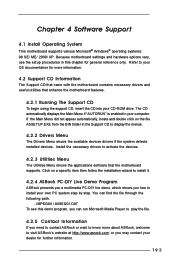
... in the Support CD to visit ASRock's website at http://www.asrock.com; Chapter 4 Software Support 4.1 Install Operating System This motherboard supports various Microsoft® Windows® operating systems: 98 SE/ ME/ 2000/ XP. Because motherboard settings and hardware options vary, use the setup procedures in your OS documentation for more about ASRock, welcome to display the menus. 4.2.2 Drivers Menu The Drivers Menu shows the available devices drivers if the system detects installed devices.
... in the Support CD to visit ASRock's website at http://www.asrock.com; Chapter 4 Software Support 4.1 Install Operating System This motherboard supports various Microsoft® Windows® operating systems: 98 SE/ ME/ 2000/ XP. Because motherboard settings and hardware options vary, use the setup procedures in your OS documentation for more about ASRock, welcome to display the menus. 4.2.2 Drivers Menu The Drivers Menu shows the available devices drivers if the system detects installed devices.

User Manual
Page 20
.... Advanced BIOS Setup Menu Main Advanced AMIBIOS SETUP UTILITY - VERSION 3.31a Security Power Boot Exit Spread Spectrum Stop Empty DIMM/PCI Clock CPU Host Frequency Actual Frequency CPU Ratio Selection SDRAM Frequency Hyper Threading Technology Disabled Disabled Auto 133MHz Locked Auto Auto [ Setup Help ] to [Auto] if using Microsoft® Windows® XP, or Linux kernel version 2.4.18 or higher. Stop Empty DIMM/PCI Clock: When this feature, it will equal the core speed of the installed motherboard. SDRAM Frequency: If [Auto] is set to [Enabled], it...
.... Advanced BIOS Setup Menu Main Advanced AMIBIOS SETUP UTILITY - VERSION 3.31a Security Power Boot Exit Spread Spectrum Stop Empty DIMM/PCI Clock CPU Host Frequency Actual Frequency CPU Ratio Selection SDRAM Frequency Hyper Threading Technology Disabled Disabled Auto 133MHz Locked Auto Auto [ Setup Help ] to [Auto] if using Microsoft® Windows® XP, or Linux kernel version 2.4.18 or higher. Stop Empty DIMM/PCI Clock: When this feature, it will equal the core speed of the installed motherboard. SDRAM Frequency: If [Auto] is set to [Enabled], it...

User Manual
Page 21
USB Controller: Use this to a section of the PCI memory address range used for graphics memory. USB Device Legacy Support: Use this field at the default value unless your PCI expansion cards' specifications require other sizes. Resource Configuration: Advanced AMIBIOS SETUP UTILITY - Primary Graphics Adapter: Select PCI, OnBoard VGA, or Add-on AGP as mouse, keyboard,... Chipset Configuration: Advanced AMIBIOS SETUP UTILITY - F1:Help Esc:Previous Menu :Select Item +/-:Change Values Enter:Select Sub-Menu F9:Setup Defaults F10:Save & Exit AGP Aperture Size: It refers ...
USB Controller: Use this to a section of the PCI memory address range used for graphics memory. USB Device Legacy Support: Use this field at the default value unless your PCI expansion cards' specifications require other sizes. Resource Configuration: Advanced AMIBIOS SETUP UTILITY - Primary Graphics Adapter: Select PCI, OnBoard VGA, or Add-on AGP as mouse, keyboard,... Chipset Configuration: Advanced AMIBIOS SETUP UTILITY - F1:Help Esc:Previous Menu :Select Item +/-:Change Values Enter:Select Sub-Menu F9:Setup Defaults F10:Save & Exit AGP Aperture Size: It refers ...

User Manual
Page 22
... ] OnBoard FDC OnBoard Serial Port OnBoard Infrared Port OnBoard Parallel Port Parallel Port Mode EPP Version Parallel Port IRQ Parallel Port DMA Channel OnBoard Midi Port Midi IRQ Select OnBoard Game Port OnBoard IDE OnBoard LAN OnBoard AC' 97 Audio OnBoard MC' 97 Modem Auto Auto Auto Auto Normal N/A Auto N/A Disabled 5 Disabled Disabled Disabled Auto Disabled to enable or disable floppy drive controller. System Hardware Monitor: You can check the status of the parallel port. Midi IRQ Select: Use this to enable or disable the floppy drive controller. Parallel Port Mode: Set...
... ] OnBoard FDC OnBoard Serial Port OnBoard Infrared Port OnBoard Parallel Port Parallel Port Mode EPP Version Parallel Port IRQ Parallel Port DMA Channel OnBoard Midi Port Midi IRQ Select OnBoard Game Port OnBoard IDE OnBoard LAN OnBoard AC' 97 Audio OnBoard MC' 97 Modem Auto Auto Auto Auto Normal N/A Auto N/A Disabled 5 Disabled Disabled Disabled Auto Disabled to enable or disable floppy drive controller. System Hardware Monitor: You can check the status of the parallel port. Midi IRQ Select: Use this to enable or disable the floppy drive controller. Parallel Port Mode: Set...
User Manual
Page 23
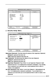
... Setup Menu F9:Setup Defaults F10:Save & Exit Main Advanced AMIBIOS SETUP UTILITY - User Password: This field shows the status of the Supervisor Password. [Clear]: No password has been set. [Set]: Supervisor password has been set . VERSION 3.31a System Hardware Monitor [ Setup Help ] CPU Temperature M/B Temperature CPU Fan Speed Chassis Fan Speed Vcore + 3.30V + 5.00V +12.00V 35 C / 95 F 27 C / 82 F 3110 RPM 0 RPM 1.728 V 3.312 V 4.975 V 12.167 V F1:Help Esc:Previous Menu :Select Item +/-:Change Values Enter:Select Sub-Menu 2. Password...
... Setup Menu F9:Setup Defaults F10:Save & Exit Main Advanced AMIBIOS SETUP UTILITY - User Password: This field shows the status of the Supervisor Password. [Clear]: No password has been set. [Set]: Supervisor password has been set . VERSION 3.31a System Hardware Monitor [ Setup Help ] CPU Temperature M/B Temperature CPU Fan Speed Chassis Fan Speed Vcore + 3.30V + 5.00V +12.00V 35 C / 95 F 27 C / 82 F 3110 RPM 0 RPM 1.728 V 3.312 V 4.975 V 12.167 V F1:Help Esc:Previous Menu :Select Item +/-:Change Values Enter:Select Sub-Menu 2. Password...

User Manual
Page 24
... the power-soft-off mode. It is selected, the AC power resumes and the system starts to enable this to enable or disable Ring-in signals to turn on the system. If [Power On] is recommended to boot up when the power recovers. Ring-In Power On: Use this feature under Microsoft® Windows® 98 / ME. Configuration options: [Setup], [Always]. PCI Devices Power On: Use this to enable or disable PS/2 keyboard to power...
... the power-soft-off mode. It is selected, the AC power resumes and the system starts to enable this to enable or disable Ring-in signals to turn on the system. If [Power On] is recommended to boot up when the power recovers. Ring-In Power On: Use this feature under Microsoft® Windows® 98 / ME. Configuration options: [Setup], [Always]. PCI Devices Power On: Use this to enable or disable PS/2 keyboard to power...

User Manual
Page 25
... enables boot up routine by skipping memory retestings. Exit Menu Main Advanced AMIBIOS SETUP UTILITY - If you press , it will appear. VERSION 3.31a Security Power Boot Exit Quick Boot Mode Boot Up Num-Lock Boot To OS/2 Boot Device Priority Disabled Off No [ Setup Help ] to set the boot device priority. 5. Boot Up Num-Lock: This automatically activates the Numeric Lock function after boot up. VERSION 3.31a Security Power Boot Exit Exit Saving Changes Exit Discarding Changes Load Default Settings Discard Changes [ Enter ] [ Enter ] [ Enter ] [ Enter ] [ Setup...
... enables boot up routine by skipping memory retestings. Exit Menu Main Advanced AMIBIOS SETUP UTILITY - If you press , it will appear. VERSION 3.31a Security Power Boot Exit Quick Boot Mode Boot Up Num-Lock Boot To OS/2 Boot Device Priority Disabled Off No [ Setup Help ] to set the boot device priority. 5. Boot Up Num-Lock: This automatically activates the Numeric Lock function after boot up. VERSION 3.31a Security Power Boot Exit Exit Saving Changes Exit Discarding Changes Load Default Settings Discard Changes [ Enter ] [ Enter ] [ Enter ] [ Enter ] [ Setup...


